2000 DODGE NEON clutch
[x] Cancel search: clutchPage 121 of 1285
REMOVAL
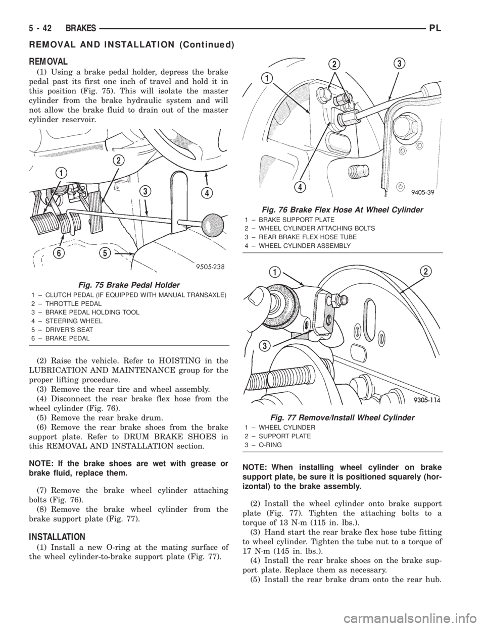
(1) Using a brake pedal holder, depress the brake
pedal past its first one inch of travel and hold it in
this position (Fig. 75). This will isolate the master
cylinder from the brake hydraulic system and will
not allow the brake fluid to drain out of the master
cylinder reservoir.
(2) Raise the vehicle. Refer to HOISTING in the
LUBRICATION AND MAINTENANCE group for the
proper lifting procedure.
(3) Remove the rear tire and wheel assembly.
(4) Disconnect the rear brake flex hose from the
wheel cylinder (Fig. 76).
(5) Remove the rear brake drum.
(6) Remove the rear brake shoes from the brake
support plate. Refer to DRUM BRAKE SHOES in
this REMOVAL AND INSTALLATION section.
NOTE: If the brake shoes are wet with grease or
brake fluid, replace them.
(7) Remove the brake wheel cylinder attaching
bolts (Fig. 76).
(8) Remove the brake wheel cylinder from the
brake support plate (Fig. 77).
INSTALLATION
(1) Install a new O-ring at the mating surface of
the wheel cylinder-to-brake support plate (Fig. 77).NOTE: When installing wheel cylinder on brake
support plate, be sure it is positioned squarely (hor-
izontal) to the brake assembly.
(2) Install the wheel cylinder onto brake support
plate (Fig. 77). Tighten the attaching bolts to a
torque of 13 N´m (115 in. lbs.).
(3) Hand start the rear brake flex hose tube fitting
to wheel cylinder. Tighten the tube nut to a torque of
17 N´m (145 in. lbs.).
(4) Install the rear brake shoes on the brake sup-
port plate. Replace them as necessary.
(5) Install the rear brake drum onto the rear hub.
Fig. 75 Brake Pedal Holder
1 ± CLUTCH PEDAL (IF EQUIPPED WITH MANUAL TRANSAXLE)
2 ± THROTTLE PEDAL
3 ± BRAKE PEDAL HOLDING TOOL
4 ± STEERING WHEEL
5 ± DRIVER'S SEAT
6 ± BRAKE PEDAL
Fig. 76 Brake Flex Hose At Wheel Cylinder
1 ± BRAKE SUPPORT PLATE
2 ± WHEEL CYLINDER ATTACHING BOLTS
3 ± REAR BRAKE FLEX HOSE TUBE
4 ± WHEEL CYLINDER ASSEMBLY
Fig. 77 Remove/Install Wheel Cylinder
1 ± WHEEL CYLINDER
2 ± SUPPORT PLATE
3 ± O-RING
5 - 42 BRAKESPL
REMOVAL AND INSTALLATION (Continued)
Page 125 of 1285

(4) Remove the brake drum (Fig. 87).
NOTE: If the drum does not come off, further brake
clearance can be obtained by backing off the brake
automatic adjuster screw. Remove the rubber plug
from the top of brake support plate. Rotate the
automatic adjuster screw in an upward motion,
using a screwdriver.
INSTALLATION
NOTE: Before installing the drum, inspect the brake
shoe linings for wear, shoe alignment, and contam-
ination.
(1) Install the rear brake drum on rear hub and
bearing (Fig. 87).
(2) Install the tire and wheel assembly. Tighten
the wheel mounting nuts to a torque of 135 N´m (100
ft. lbs.).
(3) Adjust the rear brake shoes as necessary. Refer
to ADJUSTMENTS in this section of this service
manual group.
(4) Lower the vehicle.
DRUM BRAKE SHOE SUPPORT PLATE (REAR)
NOTE: Before proceeding with this procedure,
review SERVICE WARNINGS AND CAUTIONS at the
beginning of REMOVAL AND INSTALLATION in this
section.
REMOVAL
(1) Using a brake pedal holding tool as shown (Fig.
88), depress the brake pedal past its first one inch of
travel and hold it in this position. This will isolate
the master cylinder from the brake hydraulic system
and will not allow the brake fluid to drain out of the
master cylinder reservoir.
(2) Raise the vehicle. Refer to HOISTING in the
LUBRICATION AND MAINTENANCE group for the
proper lifting procedure.
(3) Remove the rear tire and wheel assembly from
the vehicle.
(4) Disconnect the rear brake flex hose from the
wheel cylinder (Fig. 89).
(5) Remove the rear brake drum.
(6) Remove the dust cap (Fig. 90) from the rear
hub and bearing.
(7) Remove the nut (Fig. 91) holding the rear hub
and bearing to the spindle. Remove the hub and
bearing from the spindle.
(8) Remove the rear brake shoes from the brake
support plate. Refer to DRUM BRAKE SHOES in
this REMOVAL AND INSTALLATION section.(9) Remove the parking brake actuator lever from
the parking brake cable.
(10) Position a 1/2 inch wrench over the retainer
fingers on the end of the parking brake cable (Fig.
92). Compress the cable housing retaining fingers
with the wrench, then pull the cable housing out of
the support plate. Remove the wrench as the parking
brake cable retainer is freed from the mounting hole
in the brake support plate.
Fig. 88 Brake Pedal Holding Tool
1 ± CLUTCH PEDAL (IF EQUIPPED WITH MANUAL TRANSAXLE)
2 ± THROTTLE PEDAL
3 ± BRAKE PEDAL HOLDING TOOL
4 ± STEERING WHEEL
5 ± DRIVER'S SEAT
6 ± BRAKE PEDAL
Fig. 89 Brake Flex Hose At Wheel Cylinder
1 ± BRAKE SUPPORT PLATE
2 ± WHEEL CYLINDER ATTACHING BOLTS
3 ± REAR BRAKE FLEX HOSE TUBE
4 ± WHEEL CYLINDER ASSEMBLY
5 - 46 BRAKESPL
REMOVAL AND INSTALLATION (Continued)
Page 159 of 1285
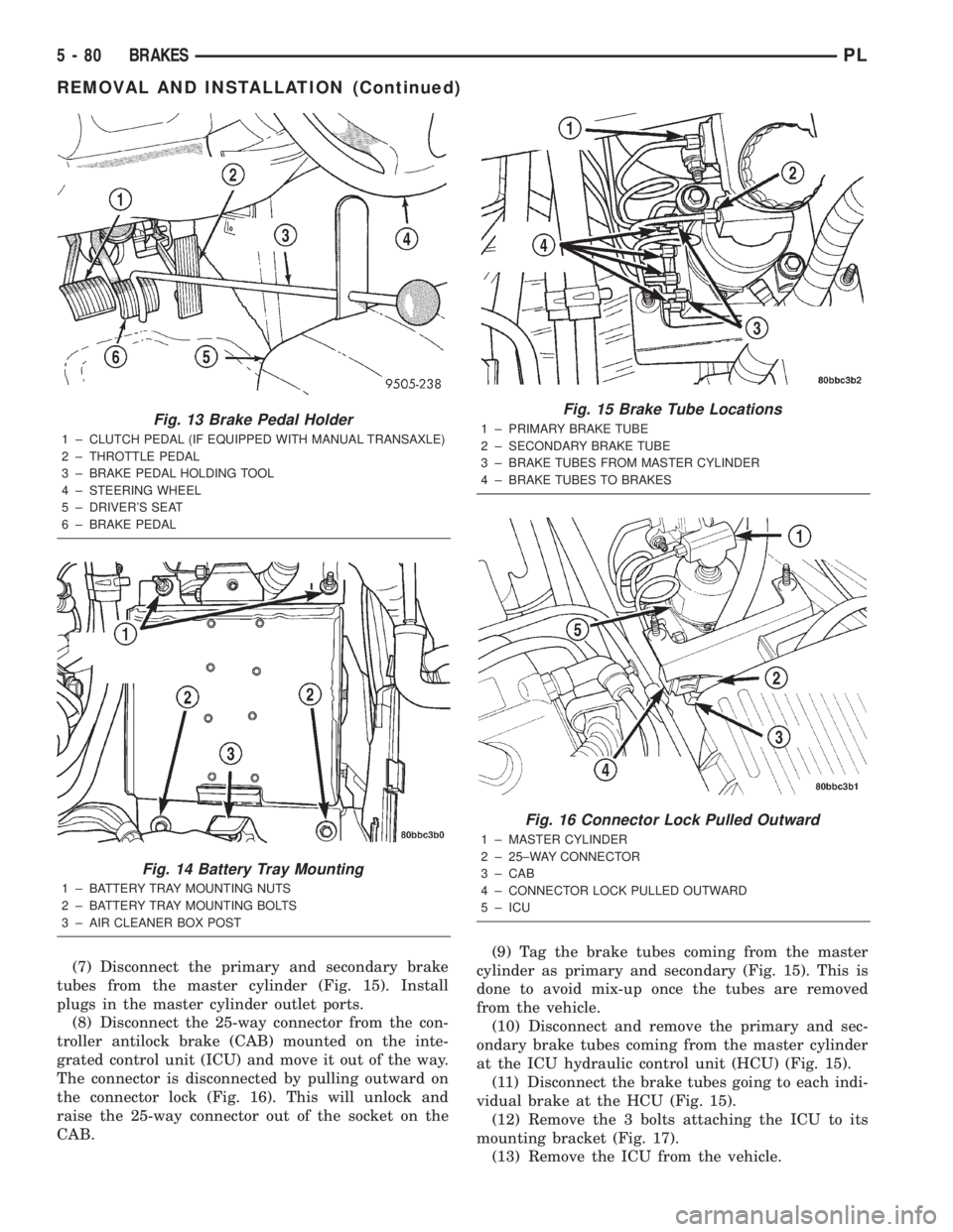
(7) Disconnect the primary and secondary brake
tubes from the master cylinder (Fig. 15). Install
plugs in the master cylinder outlet ports.
(8) Disconnect the 25-way connector from the con-
troller antilock brake (CAB) mounted on the inte-
grated control unit (ICU) and move it out of the way.
The connector is disconnected by pulling outward on
the connector lock (Fig. 16). This will unlock and
raise the 25-way connector out of the socket on the
CAB.(9) Tag the brake tubes coming from the master
cylinder as primary and secondary (Fig. 15). This is
done to avoid mix-up once the tubes are removed
from the vehicle.
(10) Disconnect and remove the primary and sec-
ondary brake tubes coming from the master cylinder
at the ICU hydraulic control unit (HCU) (Fig. 15).
(11) Disconnect the brake tubes going to each indi-
vidual brake at the HCU (Fig. 15).
(12) Remove the 3 bolts attaching the ICU to its
mounting bracket (Fig. 17).
(13) Remove the ICU from the vehicle.
Fig. 13 Brake Pedal Holder
1 ± CLUTCH PEDAL (IF EQUIPPED WITH MANUAL TRANSAXLE)
2 ± THROTTLE PEDAL
3 ± BRAKE PEDAL HOLDING TOOL
4 ± STEERING WHEEL
5 ± DRIVER'S SEAT
6 ± BRAKE PEDAL
Fig. 14 Battery Tray Mounting
1 ± BATTERY TRAY MOUNTING NUTS
2 ± BATTERY TRAY MOUNTING BOLTS
3 ± AIR CLEANER BOX POST
Fig. 15 Brake Tube Locations
1 ± PRIMARY BRAKE TUBE
2 ± SECONDARY BRAKE TUBE
3 ± BRAKE TUBES FROM MASTER CYLINDER
4 ± BRAKE TUBES TO BRAKES
Fig. 16 Connector Lock Pulled Outward
1 ± MASTER CYLINDER
2 ± 25±WAY CONNECTOR
3 ± CAB
4 ± CONNECTOR LOCK PULLED OUTWARD
5 ± ICU
5 - 80 BRAKESPL
REMOVAL AND INSTALLATION (Continued)
Page 166 of 1285
CLUTCH
TABLE OF CONTENTS
page page
DESCRIPTION AND OPERATION
MODULAR CLUTCH ASSEMBLY..............1
CLUTCH CABLE..........................1
CLUTCH INTERLOCK/UPSTOP SWITCH........1
DIAGNOSIS AND TESTING
CLUTCH SYSTEM DIAGNOSIS...............2
DRIVE PLATE MISALIGNMENT..............5
CLUTCH CHATTER COMPLAINTS............5
CLASH±INTO±REVERSE COMPLAINTS........5
CLUTCH INTERLOCK/UPSTOP SWITCH........5REMOVAL AND INSTALLATION
CLUTCH CABLE..........................7
CLUTCH INTERLOCK/UPSTOP SWITCH........8
MODULAR CLUTCH ASSEMBLY..............8
RELEASE BEARING AND FORK.............12
CLEANING AND INSPECTION
CLUTCH CONTAMINATION.................12
CLEANING PRECAUTIONS.................13
SPECIFICATIONS
TORQUE...............................13
DESCRIPTION AND OPERATION
MODULAR CLUTCH ASSEMBLY
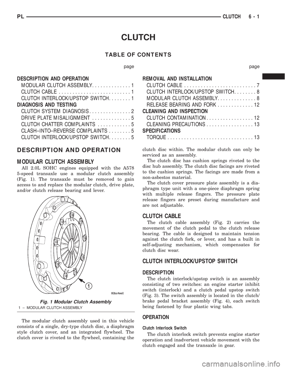
All 2.0L SOHC engines equipped with the A578
5-speed transaxle use a modular clutch assembly
(Fig. 1). The transaxle must be removed to gain
access to and replace the modular clutch, drive plate,
and/or clutch release bearing and lever.
The modular clutch assembly used in this vehicle
consists of a single, dry-type clutch disc, a diaphragm
style clutch cover, and an integrated flywheel. The
clutch cover is riveted to the flywheel, containing theclutch disc within. The modular clutch can only be
serviced as an assembly.
The clutch disc has cushion springs riveted to the
disc hub assembly. The clutch disc facings are riveted
to the cushion springs. The facings are made from a
non-asbestos material.
The clutch cover pressure plate assembly is a dia-
phragm type unit with a one-piece diaphragm spring
with multiple release fingers. The pressure plate
release fingers are preset during manufacture and
are not adjustable.
CLUTCH CABLE
The clutch cable assembly (Fig. 2) carries the
movement of the clutch pedal to the clutch release
bearing. The cable is designed to maintain tension
against the clutch fork, or lever, and has a built in
self-adjusting mechanism, which compensates for
clutch disc wear.
CLUTCH INTERLOCK/UPSTOP SWITCH
DESCRIPTION
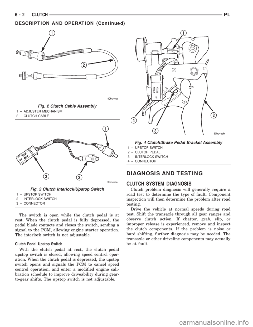
The clutch interlock/upstop switch is an assembly
consisting of two switches: an engine starter inhibit
switch (interlock) and a clutch pedal upstop switch
(Fig. 3). The switch assembly is located in the clutch/
brake pedal bracket assembly (Fig. 4), each switch
being fastened by four plastic wing tabs.
OPERATION
Clutch Interlock Switch
The clutch interlock switch prevents engine starter
operation and inadvertent vehicle movement with the
clutch engaged and the transaxle in gear.
Fig. 1 Modular Clutch Assembly
1 ± MODULAR CLUTCH ASSEMBLY
PLCLUTCH 6 - 1
Page 167 of 1285
The switch is open while the clutch pedal is at
rest. When the clutch pedal is fully depressed, the
pedal blade contacts and closes the switch, sending a
signal to the PCM, allowing engine starter operation.
The interlock switch is not adjustable.
Clutch Pedal Upstop Switch
With the clutch pedal at rest, the clutch pedal
upstop switch is closed, allowing speed control oper-
ation. When the clutch pedal is depressed, the upstop
switch opens and signals the PCM to cancel speed
control operation, and enter a modified engine cali-
bration schedule to improve driveability during gear-
to-gear shifts. The upstop switch is not adjustable.
DIAGNOSIS AND TESTING
CLUTCH SYSTEM DIAGNOSIS
Clutch problem diagnosis will generally require a
road test to determine the type of fault. Component
inspection will then determine the problem after road
testing.
Drive the vehicle at normal speeds during road
test. Shift the transaxle through all gear ranges and
observe clutch action. If chatter, grab, slip, or
improper release is experienced, remove and inspect
the clutch components. If the problem is noise or
hard shifting, further diagnosis may be needed. The
transaxle or other driveline components may actually
be at fault.
Fig. 2 Clutch Cable Assembly
1 ± ADJUSTER MECHANISM
2 ± CLUTCH CABLE
Fig. 3 Clutch Interlock/Upstop Switch
1 ± UPSTOP SWITCH
2 ± INTERLOCK SWITCH
3 ± CONNECTOR
Fig. 4 Clutch/Brake Pedal Bracket Assembly
1 ± UPSTOP SWITCH
2 ± CLUTCH PEDAL
3 ± INTERLOCK SWITCH
4 ± CONNECTOR
6 - 2 CLUTCHPL
DESCRIPTION AND OPERATION (Continued)
Page 168 of 1285
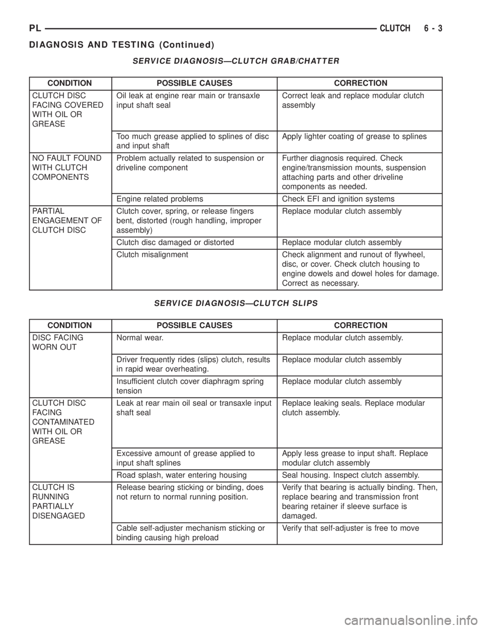
SERVICE DIAGNOSISÐCLUTCH GRAB/CHATTER
CONDITION POSSIBLE CAUSES CORRECTION
CLUTCH DISC
FACING COVERED
WITH OIL OR
GREASEOil leak at engine rear main or transaxle
input shaft sealCorrect leak and replace modular clutch
assembly
Too much grease applied to splines of disc
and input shaftApply lighter coating of grease to splines
NO FAULT FOUND
WITH CLUTCH
COMPONENTSProblem actually related to suspension or
driveline componentFurther diagnosis required. Check
engine/transmission mounts, suspension
attaching parts and other driveline
components as needed.
Engine related problems Check EFI and ignition systems
PARTIAL
ENGAGEMENT OF
CLUTCH DISCClutch cover, spring, or release fingers
bent, distorted (rough handling, improper
assembly)Replace modular clutch assembly
Clutch disc damaged or distorted Replace modular clutch assembly
Clutch misalignment Check alignment and runout of flywheel,
disc, or cover. Check clutch housing to
engine dowels and dowel holes for damage.
Correct as necessary.
SERVICE DIAGNOSISÐCLUTCH SLIPS
CONDITION POSSIBLE CAUSES CORRECTION
DISC FACING
WORN OUTNormal wear. Replace modular clutch assembly.
Driver frequently rides (slips) clutch, results
in rapid wear overheating.Replace modular clutch assembly
Insufficient clutch cover diaphragm spring
tensionReplace modular clutch assembly
CLUTCH DISC
FACING
CONTAMINATED
WITH OIL OR
GREASELeak at rear main oil seal or transaxle input
shaft sealReplace leaking seals. Replace modular
clutch assembly.
Excessive amount of grease applied to
input shaft splinesApply less grease to input shaft. Replace
modular clutch assembly
Road splash, water entering housing Seal housing. Inspect clutch assembly.
CLUTCH IS
RUNNING
PARTIALLY
DISENGAGEDRelease bearing sticking or binding, does
not return to normal running position.Verify that bearing is actually binding. Then,
replace bearing and transmission front
bearing retainer if sleeve surface is
damaged.
Cable self-adjuster mechanism sticking or
binding causing high preloadVerify that self-adjuster is free to move
PLCLUTCH 6 - 3
DIAGNOSIS AND TESTING (Continued)
Page 169 of 1285
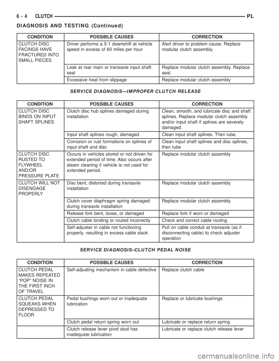
CONDITION POSSIBLE CAUSES CORRECTION
CLUTCH DISC
FACINGS HAVE
FRACTURED INTO
SMALL PIECESDriver performs a 5-1 downshift at vehicle
speed in excess of 60 miles per hourAlert driver to problem cause. Replace
modular clutch assembly.
Leak at rear main or transaxle input shaft
sealReplace modular clutch assembly. Replace
seal.
Excessive heat from slippage Replace modular clutch assembly
SERVICE DIAGNOSISÐIMPROPER CLUTCH RELEASE
CONDITION POSSIBLE CAUSES CORRECTION
CLUTCH DISC
BINDS ON INPUT
SHAFT SPLINESClutch disc hub splines damaged during
installationClean, smooth, and lubricate disc and shaft
splines. Replace modular clutch assembly
and/or input shaft if splines are severely
damaged.
Input shaft splines rough, damaged. Clean input shaft splines. Then lube.
Corrosion or rust formations on splines of
input shaft and discClean input shaft splines and disc splines,
then lube
CLUTCH DISC
RUSTED TO
FLYWHEEL
AND/OR
PRESSURE PLATEOccurs in vehicles stored or not driven for
extended period of time. Also occurs after
steam cleaning if vehicle is not used for
extended period.Replace modular clutch assembly
CLUTCH WILL NOT
DISENGAGE
PROPERLYDisc bent, distorted during transaxle
installationReplace modular clutch assembly
Clutch cover diaphragm spring damaged
during transaxle installationReplace modular clutch assembly
Release fork bent, loose, or damaged Replace fork if worn or damaged
Clutch cable binding or routed incorrectly Check and correct cable routing
Self-adjuster in cable not functioning
properly, resulting in excess cable slackPull on cable conduit at transaxle (as if
disconnecting cable) to check adjuster
operation
SERVICE DIAGNOSIS±CLUTCH PEDAL NOISE
CONDITION POSSIBLE CAUSES CORRECTION
CLUTCH PEDAL
MAKES REPEATED
ªPOPº NOISE IN
THE FIRST INCH
OF TRAVELSelf-adjusting mechanism in cable defective Replace clutch cable
CLUTCH PEDAL
SQUEAKS WHEN
DEPRESSED TO
FLOORPedal bushings worn out or inadequate
lubricationReplace or lubricate bushings
Clutch pedal return spring worn out Lubricate or replace return spring
Clutch release lever pivot stud has
inadequate lubricationLubricate or replace clutch release lever
6 - 4 CLUTCHPL
DIAGNOSIS AND TESTING (Continued)
Page 170 of 1285
DRIVE PLATE MISALIGNMENT
Common causes of misalignment are:
²Heat warping
²Mounting drive plate on a dirty crankshaft
flange
²Incorrect bolt tightening
²Improper seating on the crankshaft shoulder
²Loose crankshaft bolts
Clean the crankshaft flange before mounting the
drive plate. Dirt and grease on the flange surface
may misalign the flywheel, causing excessive runout.
Use new bolts when mounting drive plate to crank-
shaft. Tighten drive plate bolts to specified torque
only. Over-tightening can distort the drive plate hub
causing excessive runout.
CLUTCH CHATTER COMPLAINTS
For all clutch chatter complaints, do the following:
(1) Check for loose, misaligned, or broken engine
and transmission mounts. If present, they should be
corrected at this time. Test vehicle for chatter. If
chatter is gone, there is no need to go any further. If
chatter persists:
(2) Check to see if clutch cable routing is correct
and operates smoothly.
(3) Check for loose connections in drive train. Cor-
rect any problems and determine if clutch chatter
complaints have been satisfied. If not:
(4) Remove transaxle. See Group 21, Manual Tran-
saxle for procedure.
(5) Check to see if the release bearing is sticky or
binding. Replace bearing, if needed.
(6) Check linkage for excessive wear on the pivot
stud and fork fingers. Replace all worn parts.
(7) Check clutch assembly for contamination (dirt,
oil). Replace clutch assembly, if required.
(8) Check to see if the clutch disc hub splines are
damaged. Replace with new clutch assembly, if nec-
essary.
(9) Check input shaft splines for damage. Replace,
if necessary.
(10) Check for uneven wear on clutch fingers.
(11) Check for broken clutch cover diaphragm
spring fingers. Replace with new clutch assembly, if
necessary.
CLASH±INTO±REVERSE COMPLAINTS
Certain NV T350 (A-578) manual transaxles are
equipped with a reverse brake. It prevents clash
when shifting into reverse, but only if the vehicle is
not moving. See Group 21, Transaxle for further
diagnosis.
(1) Depress clutch pedal to floor and hold. After
three seconds, shift to reverse. If clash is present,
clutch has excessive spin time, and the reverse brake
may not be functioning.(2) Remove transaxle. See Group 21, Manual Tran-
saxle for procedure.
(3) Check the input shaft spline, clutch disc
splines, and release bearing for dry rust. If present,
clean rust off and apply a light coat of bearing grease
to the input shaft splines. Apply grease on the input
shaft splines only where the clutch disc slides. Verify
that the clutch disc slides freely along the input shaft
spline.
(4) Check to see if the clutch disc hub splines are
damaged, and replace with new clutch assembly if
required.
(5) Check the input shaft for damaged splines.
Replace as necessary.
(6) Check for broken clutch cover diaphragm
spring fingers.
(7) Install clutch assembly and transaxle.
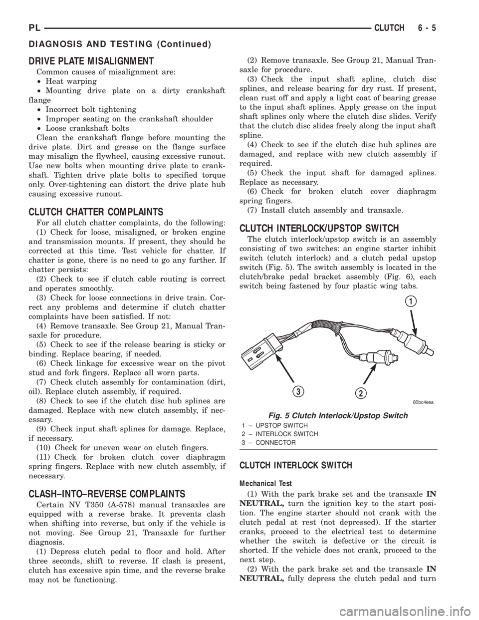
CLUTCH INTERLOCK/UPSTOP SWITCH
The clutch interlock/upstop switch is an assembly
consisting of two switches: an engine starter inhibit
switch (clutch interlock) and a clutch pedal upstop
switch (Fig. 5). The switch assembly is located in the
clutch/brake pedal bracket assembly (Fig. 6), each
switch being fastened by four plastic wing tabs.
CLUTCH INTERLOCK SWITCH
Mechanical Test
(1) With the park brake set and the transaxleIN
NEUTRAL,turn the ignition key to the start posi-
tion. The engine starter should not crank with the
clutch pedal at rest (not depressed). If the starter
cranks, proceed to the electrical test to determine
whether the switch is defective or the circuit is
shorted. If the vehicle does not crank, proceed to the
next step.
(2) With the park brake set and the transaxleIN
NEUTRAL,fully depress the clutch pedal and turn
Fig. 5 Clutch Interlock/Upstop Switch
1 ± UPSTOP SWITCH
2 ± INTERLOCK SWITCH
3 ± CONNECTOR
PLCLUTCH 6 - 5
DIAGNOSIS AND TESTING (Continued)