2000 DODGE NEON catalytic converter
[x] Cancel search: catalytic converterPage 823 of 1285
REFORMULATED GASOLINE
Many areas of the country require the use of
cleaner burning gasoline referred to as ªreformulat-
edº gasoline. Reformulated gasoline contain oxygen-
ates, and are specifically blended to reduce vehicle
emissions and improve air quality.
DaimlerChrysler Corporation strongly supports the
use of reformulated gasoline. Properly blended refor-
mulated gasoline will provide excellent performance
and durability for the engine and fuel system compo-
nents.
GASOLINE/OXYGENATE BLENDS
Some fuel suppliers blend unleaded gasoline with
oxygenates such as 10% ethanol, MTBE, and ETBE.
Oxygenates are required in some areas of the country
during the winter months to reduce carbon monoxide
emissions. Fuels blended with these oxygenates may
be used in your vehicle.
CAUTION: DO NOT use gasoline containing METH-
ANOL. Gasoline containing methanol may damage
critical fuel system components.
MMT
MMT is a manganese-containing metallic additive
that is blended into some gasoline to increase octane.
Gasoline blended with MMT provide no performance
advantage beyond gasoline of the same octane num-
ber without MMT. Gasoline blended with MMT
reduce spark plug life and reduce emission system
performance in some vehicles. DaimlerChrysler rec-
ommends that gasoline without MMT be used in your
vehicle. The MMT content of gasoline may not be
indicated on the gasoline pump; therefore, you should
ask your gasoline retailer whether or not his/her gas-
oline contains MMT.
It is even more important to look for gasoline with-
out MMT in Canada because MMT can be used at
levels higher than allowed in the United States.
MMT is prohibited in Federal and California refor-
mulated gasoline.
SULFUR IN GASOLINE
If you live in the northeast United States, your
vehicle may have been designed to meet California
low emission standards with clean-burning, low-sul-
fur, California gasoline. Gasoline sold outside of Cal-
ifornia is permitted to have higher sulfur levels
which may affect the performance of the vehicle's cat-
alytic converter. This may cause the Check Engine or
Service Engine Soon light to illuminate.
Illumination of either light while operating on high
sulfur gasoline does not necessarily mean your emis-
sion control system is malfunctioning. DaimlerChrysler
recommends that you try a different brand of unleadedgasoline having lower sulfur to determine if the prob-
lem is fuel related prior to returning your vehicle to an
authorized dealer for service.
CAUTION: If the Check Engine or Service Engine
Soon light is flashing, immediate service is
required; see on-board diagnostics system section.
MATERIALS ADDED TO FUEL
All gasoline sold in the United States and Canada
are required to contain effective detergent additives.
Use of additional detergents or other additives is not
needed under normal conditions.
FUEL SYSTEM CAUTIONS
CAUTION: Follow these guidelines to maintain your
vehicle's performance:
²The use of leaded gas is prohibited by Federal
law. Using leaded gasoline can impair engine perfor-
mance, damage the emission control system, and
could result in loss of warranty coverage.
²An out-of-tune engine, or certain fuel or ignition
malfunctions, can cause the catalytic converter to
overheat. If you notice a pungent burning odor or
some light smoke, your engine may be out of tune or
malfunctioning and may require immediate service.
Contact your dealer for service assistance.
²When pulling a heavy load or driving a fully
loaded vehicle when the humidity is low and the tem-
perature is high, use a premium unleaded fuel to
help prevent spark knock. If spark knock persists,
lighten the load, or engine piston damage may result.
²The use of fuel additives which are now being
sold as octane enhancers is not recommended. Most
of these products contain high concentrations of
methanol. Fuel system damage or vehicle perfor-
mance problems resulting from the use of such fuels
or additives is not the responsibility of
DaimlerChrysler Corporation and may not be covered
under the new vehicle warranty.
NOTE: Intentional tampering with emissions control
systems can result in civil penalties being assessed
against you.
GASOLINE/OXYGENATE BLENDS
OPERATION
Some fuel suppliers blend unleaded gasoline with
materials that contain oxygen such as alcohol, MTBE
(Methyl Tertiary Butyl Ether) and ETBE (Ethyl Ter-
tiary Butyl Ether). Oxygenates are required in some
areas of the country during winter months to reduce
14 - 2 FUEL SYSTEMPL
DESCRIPTION AND OPERATION (Continued)
Page 854 of 1285
grammed (fixed) values and inputs from other sen-
sors.
DOWNSTREAM OXYGEN SENSOR 1/2
The Downstream O2 Sensor has two functions.
One function is measuring catalyst efficiency. This is
an OBD II requirement. The oxygen content of theexhaust gasses has significantly less fluctuation than
at the inlet if the converter is working properly. The
PCM compares upstream and Downstream O2 Sen-
sor switch rates under specific operating conditions
to determine if the catalyst is functioning properly.
The other function is a downstream fuel control
which was introduced in 1996. The upstream O2 goal
varies within the window of operation of the O2 Sen-
sor. In the past the goal was a preprogrammed fixed
value based upon where it believed the catalyst oper-
ated most efficiently.
While the Upstream O2 Sensor input is used to
maintain the 14.7:1 air/fuel ratio, variations in
engines, exhaust systems and catalytic converters
may cause this ratio to not be the most ideal for a
particular catalyst and engine. To help maintain the
catalyst operating at maximum efficiency, the PCM
will fine tune the air/fuel ratio entering the catalyst
based upon the oxygen content leaving the catalyst.
This is accomplished by modifying the Upstream O2
Sensor voltage goal.
If the exhaust leaving the catalyst has too much
oxygen (lean ) the PCM increases the upstream O2
goal which increases fuel in the mixture causing less
oxygen to be left over. Conversely, if the oxygen con-
tent leaving the catalyst has is too little oxygen (rich)
the PCM decreases the upstream O2 goal down
which removes fuel from the mixture causing more
oxygen to be left over. This function only occurs dur-
ing downstream closed loop mode operation.
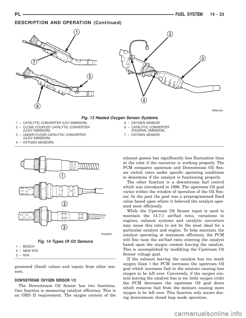
Fig. 13 Heated Oxygen Sensor Systems
1 ± CATALYTIC CONVERTER (LEV EMISSION)
2 ± CLOSE-COUPLED CATALYTIC CONVERTER
(ULEV EMISSION)
3 ± UNDER-FLOOR CATALYTIC CONVERTER
(ULEV EMISSION)
4 ± OXYGEN SENSORS5 ± OXYGEN SENSOR
6 ± CATALYTIC CONVERTER
(FEDERAL EMISSION)
7 ± OXYGEN SENSOR
Fig. 14 Types Of O2 Sensors
1 ± BOSCH
2 ± NEW NTK
3 ± NTK
PLFUEL SYSTEM 14 - 33
DESCRIPTION AND OPERATION (Continued)
Page 987 of 1285
(6) Disconnect both battery cables, remove battery
hold down clamp and bolt, and remove battery.
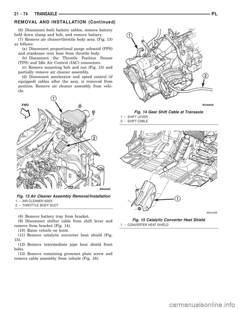
(7) Remove air cleaner/throttle body assy. (Fig. 13)
as follows:
(a) Disconnect proportional purge solenoid (PPS)
and crankcase vent hose from throttle body.
(b) Disconnect the Throttle Position Sensor
(TPS) and Idle Air Control (IAC) connectors.
(c) Remove mounting bolt and nut (Fig. 13) and
partially remove air cleaner assembly.
(d) Disconnect accelerator and speed control (if
equipped) cables after the assy. is removed from
position. Remove air cleaner assembly from vehi-
cle.
(8) Remove battery tray from bracket.
(9) Disconnect shifter cable from shift lever and
remove from bracket (Fig. 14).
(10) Raise vehicle on hoist.
(11) Remove catalytic converter heat shield (Fig.
15).
(12) Remove intermediate pipe heat shield front
bolts.
(13) Remove remaining grommet plate screw and
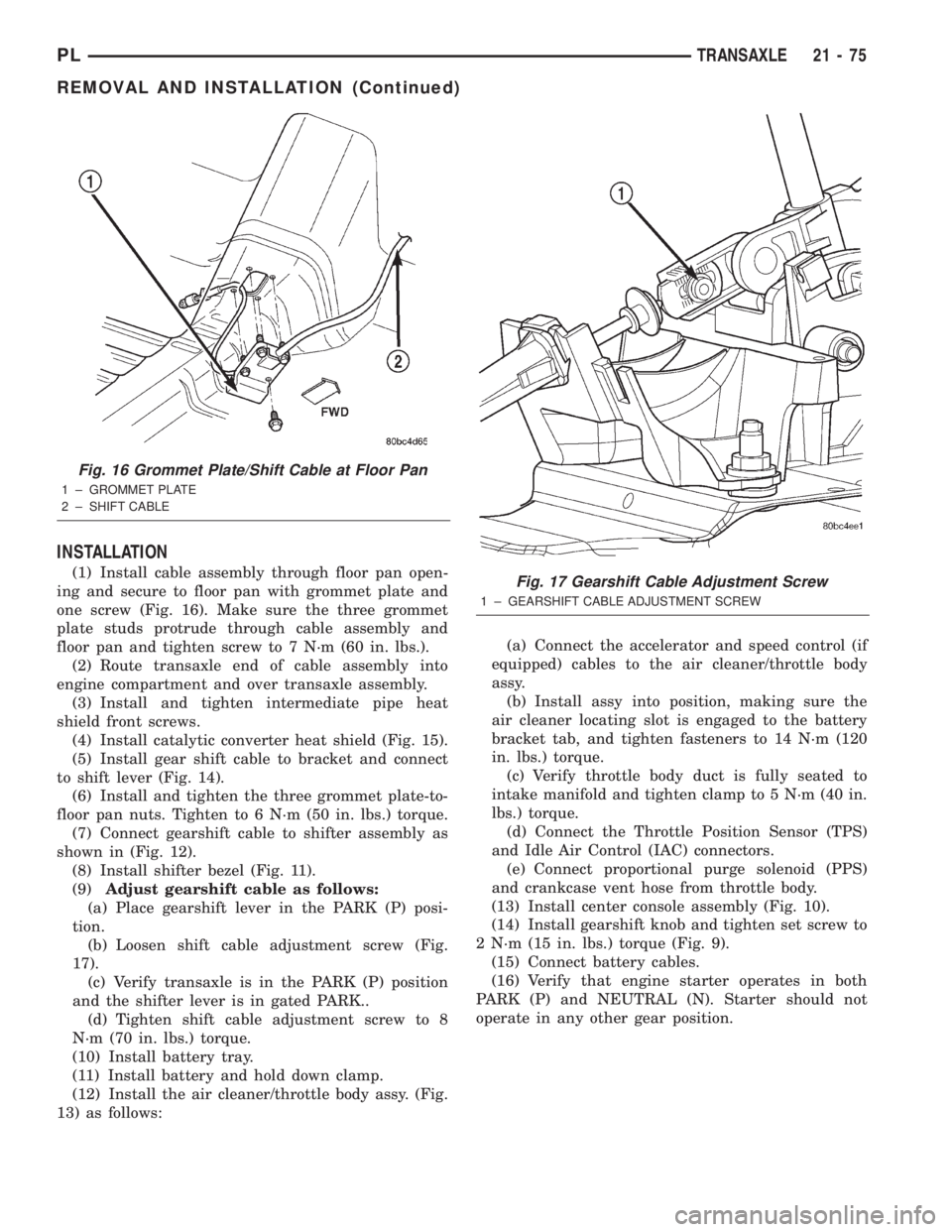
remove cable assembly from vehicle (Fig. 16).
Fig. 13 Air Cleaner Assembly Removal/Installation
1 ± AIR CLEANER ASSY.
2 ± THROTTLE BODY DUCT
Fig. 14 Gear Shift Cable at Transaxle
1 ± SHIFT LEVER
2 ± SHIFT CABLE
Fig. 15 Catalytic Converter Heat Shield
1 ± CONVERTER HEAT SHIELD
21 - 74 TRANSAXLEPL
REMOVAL AND INSTALLATION (Continued)
Page 988 of 1285
INSTALLATION
(1) Install cable assembly through floor pan open-
ing and secure to floor pan with grommet plate and
one screw (Fig. 16). Make sure the three grommet
plate studs protrude through cable assembly and
floor pan and tighten screw to 7 N´m (60 in. lbs.).
(2) Route transaxle end of cable assembly into
engine compartment and over transaxle assembly.
(3) Install and tighten intermediate pipe heat
shield front screws.
(4) Install catalytic converter heat shield (Fig. 15).
(5) Install gear shift cable to bracket and connect
to shift lever (Fig. 14).
(6) Install and tighten the three grommet plate-to-
floor pan nuts. Tighten to 6 N´m (50 in. lbs.) torque.
(7) Connect gearshift cable to shifter assembly as
shown in (Fig. 12).
(8) Install shifter bezel (Fig. 11).
(9)Adjust gearshift cable as follows:
(a) Place gearshift lever in the PARK (P) posi-
tion.
(b) Loosen shift cable adjustment screw (Fig.
17).
(c) Verify transaxle is in the PARK (P) position
and the shifter lever is in gated PARK..
(d) Tighten shift cable adjustment screw to 8
N´m (70 in. lbs.) torque.
(10) Install battery tray.
(11) Install battery and hold down clamp.
(12) Install the air cleaner/throttle body assy. (Fig.
13) as follows:(a) Connect the accelerator and speed control (if
equipped) cables to the air cleaner/throttle body
assy.
(b) Install assy into position, making sure the
air cleaner locating slot is engaged to the battery
bracket tab, and tighten fasteners to 14 N´m (120
in. lbs.) torque.
(c) Verify throttle body duct is fully seated to
intake manifold and tighten clamp to 5 N´m (40 in.
lbs.) torque.
(d) Connect the Throttle Position Sensor (TPS)
and Idle Air Control (IAC) connectors.
(e) Connect proportional purge solenoid (PPS)
and crankcase vent hose from throttle body.
(13) Install center console assembly (Fig. 10).
(14) Install gearshift knob and tighten set screw to
2 N´m (15 in. lbs.) torque (Fig. 9).
(15) Connect battery cables.
(16) Verify that engine starter operates in both
PARK (P) and NEUTRAL (N). Starter should not
operate in any other gear position.
Fig. 16 Grommet Plate/Shift Cable at Floor Pan
1 ± GROMMET PLATE
2 ± SHIFT CABLE
Fig. 17 Gearshift Cable Adjustment Screw
1 ± GEARSHIFT CABLE ADJUSTMENT SCREW
PLTRANSAXLE 21 - 75
REMOVAL AND INSTALLATION (Continued)
Page 1096 of 1285
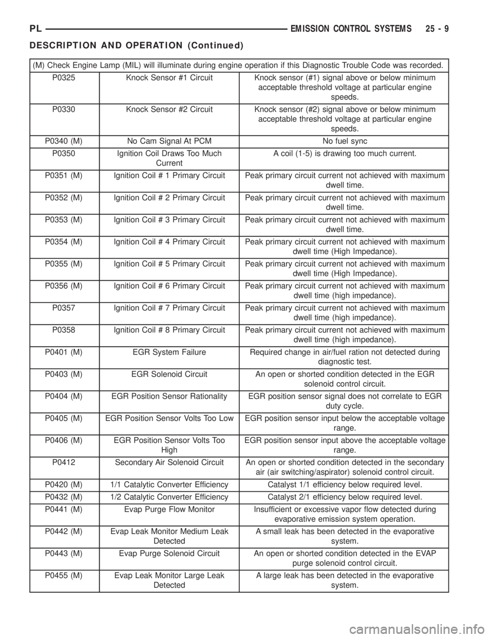
(M) Check Engine Lamp (MIL) will illuminate during engine operation if this Diagnostic Trouble Code was recorded.
P0325 Knock Sensor #1 Circuit Knock sensor (#1) signal above or below minimum
acceptable threshold voltage at particular engine
speeds.
P0330 Knock Sensor #2 Circuit Knock sensor (#2) signal above or below minimum
acceptable threshold voltage at particular engine
speeds.
P0340 (M) No Cam Signal At PCM No fuel sync
P0350 Ignition Coil Draws Too Much
CurrentA coil (1-5) is drawing too much current.
P0351 (M) Ignition Coil # 1 Primary Circuit Peak primary circuit current not achieved with maximum
dwell time.
P0352 (M) Ignition Coil # 2 Primary Circuit Peak primary circuit current not achieved with maximum
dwell time.
P0353 (M) Ignition Coil # 3 Primary Circuit Peak primary circuit current not achieved with maximum
dwell time.
P0354 (M) Ignition Coil # 4 Primary Circuit Peak primary circuit current not achieved with maximum
dwell time (High Impedance).
P0355 (M) Ignition Coil # 5 Primary Circuit Peak primary circuit current not achieved with maximum
dwell time (High Impedance).
P0356 (M) Ignition Coil # 6 Primary Circuit Peak primary circuit current not achieved with maximum
dwell time (high impedance).
P0357 Ignition Coil # 7 Primary Circuit Peak primary circuit current not achieved with maximum
dwell time (high impedance).
P0358 Ignition Coil # 8 Primary Circuit Peak primary circuit current not achieved with maximum
dwell time (high impedance).
P0401 (M) EGR System Failure Required change in air/fuel ration not detected during
diagnostic test.
P0403 (M) EGR Solenoid Circuit An open or shorted condition detected in the EGR
solenoid control circuit.
P0404 (M) EGR Position Sensor Rationality EGR position sensor signal does not correlate to EGR
duty cycle.
P0405 (M) EGR Position Sensor Volts Too Low EGR position sensor input below the acceptable voltage
range.
P0406 (M) EGR Position Sensor Volts Too
HighEGR position sensor input above the acceptable voltage
range.
P0412 Secondary Air Solenoid Circuit An open or shorted condition detected in the secondary
air (air switching/aspirator) solenoid control circuit.
P0420 (M) 1/1 Catalytic Converter Efficiency Catalyst 1/1 efficiency below required level.
P0432 (M) 1/2 Catalytic Converter Efficiency Catalyst 2/1 efficiency below required level.
P0441 (M) Evap Purge Flow Monitor Insufficient or excessive vapor flow detected during
evaporative emission system operation.
P0442 (M) Evap Leak Monitor Medium Leak
DetectedA small leak has been detected in the evaporative
system.
P0443 (M) Evap Purge Solenoid Circuit An open or shorted condition detected in the EVAP
purge solenoid control circuit.
P0455 (M) Evap Leak Monitor Large Leak
DetectedA large leak has been detected in the evaporative
system.
PLEMISSION CONTROL SYSTEMS 25 - 9
DESCRIPTION AND OPERATION (Continued)
Page 1099 of 1285
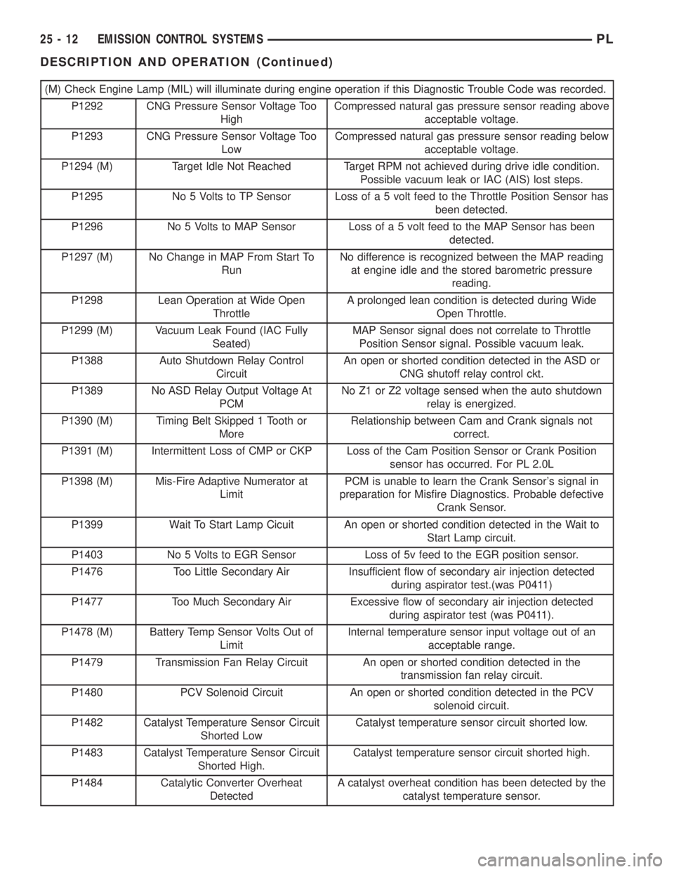
(M) Check Engine Lamp (MIL) will illuminate during engine operation if this Diagnostic Trouble Code was recorded.
P1292 CNG Pressure Sensor Voltage Too
HighCompressed natural gas pressure sensor reading above
acceptable voltage.
P1293 CNG Pressure Sensor Voltage Too
LowCompressed natural gas pressure sensor reading below
acceptable voltage.
P1294 (M) Target Idle Not Reached Target RPM not achieved during drive idle condition.
Possible vacuum leak or IAC (AIS) lost steps.
P1295 No 5 Volts to TP Sensor Loss of a 5 volt feed to the Throttle Position Sensor has
been detected.
P1296 No 5 Volts to MAP Sensor Loss of a 5 volt feed to the MAP Sensor has been
detected.
P1297 (M) No Change in MAP From Start To
RunNo difference is recognized between the MAP reading
at engine idle and the stored barometric pressure
reading.
P1298 Lean Operation at Wide Open
ThrottleA prolonged lean condition is detected during Wide
Open Throttle.
P1299 (M) Vacuum Leak Found (IAC Fully
Seated)MAP Sensor signal does not correlate to Throttle
Position Sensor signal. Possible vacuum leak.
P1388 Auto Shutdown Relay Control
CircuitAn open or shorted condition detected in the ASD or
CNG shutoff relay control ckt.
P1389 No ASD Relay Output Voltage At
PCMNo Z1 or Z2 voltage sensed when the auto shutdown
relay is energized.
P1390 (M) Timing Belt Skipped 1 Tooth or
MoreRelationship between Cam and Crank signals not
correct.
P1391 (M) Intermittent Loss of CMP or CKP Loss of the Cam Position Sensor or Crank Position
sensor has occurred. For PL 2.0L
P1398 (M) Mis-Fire Adaptive Numerator at
LimitPCM is unable to learn the Crank Sensor's signal in
preparation for Misfire Diagnostics. Probable defective
Crank Sensor.
P1399 Wait To Start Lamp Cicuit An open or shorted condition detected in the Wait to
Start Lamp circuit.
P1403 No 5 Volts to EGR Sensor Loss of 5v feed to the EGR position sensor.
P1476 Too Little Secondary Air Insufficient flow of secondary air injection detected
during aspirator test.(was P0411)
P1477 Too Much Secondary Air Excessive flow of secondary air injection detected
during aspirator test (was P0411).
P1478 (M) Battery Temp Sensor Volts Out of
LimitInternal temperature sensor input voltage out of an
acceptable range.
P1479 Transmission Fan Relay Circuit An open or shorted condition detected in the
transmission fan relay circuit.
P1480 PCV Solenoid Circuit An open or shorted condition detected in the PCV
solenoid circuit.
P1482 Catalyst Temperature Sensor Circuit
Shorted LowCatalyst temperature sensor circuit shorted low.
P1483 Catalyst Temperature Sensor Circuit
Shorted High.Catalyst temperature sensor circuit shorted high.
P1484 Catalytic Converter Overheat
DetectedA catalyst overheat condition has been detected by the
catalyst temperature sensor.
25 - 12 EMISSION CONTROL SYSTEMSPL
DESCRIPTION AND OPERATION (Continued)
Page 1103 of 1285
²200 revolution increments for immediate cata-
lyst damage
²1000 revolution increments for emissions viola-
tion and Inspection/Maintenance (I/M) test failure
NOTE: The percent of misfire for malfunction crite-
ria varies due to RPM and load. As the engine
speed increases or load decreases, the effects of a
misfire diminishes due to crankshaft momentum.
Failure percentages also vary from engine to
engine.
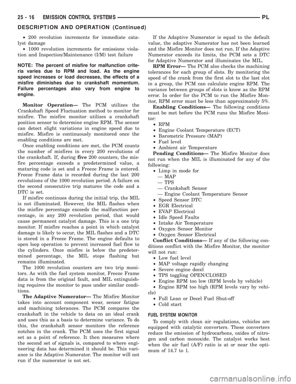
Monitor OperationÐThe PCM utilizes the
Crankshaft Speed Fluctuation method to monitor for
misfire. The misfire monitor utilizes a crankshaft
position sensor to determine engine RPM. The sensor
can detect slight variations in engine speed due to
misfire. Misfire is continuously monitored once the
enabling conditions are met.
Once enabling conditions are met, the PCM counts
the number of misfires in every 200 revolutions of
the crankshaft. If, duringfive200 counters, the mis-
fire percentage exceeds a predetermined value, a
maturing code is set and a Freeze Frame is entered.
Freeze Frame data is recorded during the last 200
revolutions of the 1000 revolution period. A failure on
the second consecutive trip matures the code and a
DTC is set.
If misfire continues during the initial trip, the MIL
is not illuminated. However, the MIL flashes when
the misfire percentage exceeds the malfunction per-
centage, in any 200 revolution period, that would
cause permanent catalyst damage. This is a one trip
monitor. If misfire reaches a point in which catalyst
damage is likely to occur, the MIL flashes and a DTC
is stored in a Freeze Frame. The engine defaults to
open loop operation to prevent increased fuel flow to
the cylinders. Once misfire is below the predeter-
mined percentage, the MIL stops flashing but
remains illuminated.
The 1000 revolution counters are two trip moni-
tors. As with the fuel system monitor, Freeze Frame
data is from the original fault, and MIL extinguish-
ing requires the monitor to pass under similar condi-
tions.
The Adaptive NumeratorÐThe Misfire Monitor
takes into account component wear, sensor fatigue
and machining tolerances. The PCM compares the
crankshaft in the vehicle to data on an ideal crank
and uses this as a basis to determine variance. To do
this, the crankshaft sensor monitors the reference
notches in the crank. The PCM uses the first signal
set as a point of reference. It then measures where
the second set of signals is, compared to where engi-
neering data has determined it should be. This vari-
ance is the Adaptive Numerator. The monitor will not
run if the numerator is not set.If the Adaptive Numerator is equal to the default
value, the adaptive Numerator has not been learned
and the Misfire Monitor does not run. If the Adaptive
Numerator exceeds its limits, the PCM sets a DTC
for Adaptive Numerator and illuminates the MIL.
RPM ErrorÐThe PCM also checks the machining
tolerances for each group of slots. By monitoring the
speed of the crank from the first slot to the last slot
in a group, the PCM can calculate engine RPM. The
variance between groups of slots is know as the RPM
error. In order for the PCM to run the Misfire Mon-
itor, RPM error must be less than approximately 5%.
Enabling ConditionsÐThe following conditions
must be met before the PCM runs the Misfire Moni-
tor:
²RPM
²Engine Coolant Temperature (ECT)
²Barometric Pressure (MAP)
²Fuel level
²Ambient air Temperature
Pending ConditionsÐThe Misfire Monitor does
not run when the MIL is illuminated for any of the
following:
²Limp in mode for
Ð MAP
Ð TPS
Ð Crankshaft Sensor
Ð Engine Coolant Temperature Sensor
²Speed Sensor DTC
²EGR Electrical
²EVAP Electrical
²Idle Speed Faults
²Intake Air Temperature
²Oxygen Sensor Monitor
²Oxygen Sensor Electrical
Conflict ConditionsÐIf any of the following con-
ditions conflict with the Misfire Monitor, the monitor
will not run:
²Low fuel level
²MAP voltage rapidly changing
²Severe engine decel
²TPS toggling OPEN/CLOSED
²Engine RPM too low (RPM levels by vehicle)
²Engine RPM too high (RPM levels vary by vehi-
cle)
²Full Lean or Decel Fuel Shut-off
²Cold start
FUEL SYSTEM MONITOR
To comply with clean air regulations, vehicles are
equipped with catalytic converters. These converters
reduce the emission of hydrocarbons, oxides of nitro-
gen and carbon monoxide. The catalyst works best
when the air fuel (A/F) ratio is at or near the opti-
mum of 14.7 to 1.
25 - 16 EMISSION CONTROL SYSTEMSPL
DESCRIPTION AND OPERATION (Continued)
Page 1109 of 1285
Pending ConditionsÐThere are not conditions
or situations that prompt conflict or suspension of
testing. The oxygen sensor heater test is not run
pending resolution of MIL illumination due to oxygen
sensor failure.
SuspendÐThere are no conditions which exist for
suspending the Heater Monitor.
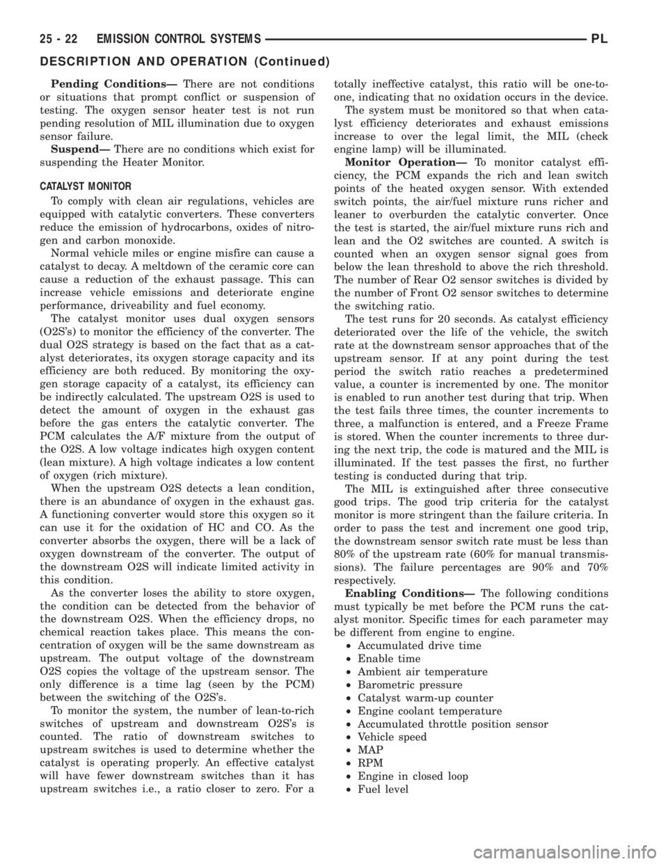
CATALYST MONITOR
To comply with clean air regulations, vehicles are
equipped with catalytic converters. These converters
reduce the emission of hydrocarbons, oxides of nitro-
gen and carbon monoxide.
Normal vehicle miles or engine misfire can cause a
catalyst to decay. A meltdown of the ceramic core can
cause a reduction of the exhaust passage. This can
increase vehicle emissions and deteriorate engine
performance, driveability and fuel economy.
The catalyst monitor uses dual oxygen sensors
(O2S's) to monitor the efficiency of the converter. The
dual O2S strategy is based on the fact that as a cat-
alyst deteriorates, its oxygen storage capacity and its
efficiency are both reduced. By monitoring the oxy-
gen storage capacity of a catalyst, its efficiency can
be indirectly calculated. The upstream O2S is used to
detect the amount of oxygen in the exhaust gas
before the gas enters the catalytic converter. The
PCM calculates the A/F mixture from the output of
the O2S. A low voltage indicates high oxygen content
(lean mixture). A high voltage indicates a low content
of oxygen (rich mixture).
When the upstream O2S detects a lean condition,
there is an abundance of oxygen in the exhaust gas.
A functioning converter would store this oxygen so it
can use it for the oxidation of HC and CO. As the
converter absorbs the oxygen, there will be a lack of
oxygen downstream of the converter. The output of
the downstream O2S will indicate limited activity in
this condition.
As the converter loses the ability to store oxygen,
the condition can be detected from the behavior of
the downstream O2S. When the efficiency drops, no
chemical reaction takes place. This means the con-
centration of oxygen will be the same downstream as
upstream. The output voltage of the downstream
O2S copies the voltage of the upstream sensor. The
only difference is a time lag (seen by the PCM)
between the switching of the O2S's.
To monitor the system, the number of lean-to-rich
switches of upstream and downstream O2S's is
counted. The ratio of downstream switches to
upstream switches is used to determine whether the
catalyst is operating properly. An effective catalyst
will have fewer downstream switches than it has
upstream switches i.e., a ratio closer to zero. For atotally ineffective catalyst, this ratio will be one-to-
one, indicating that no oxidation occurs in the device.
The system must be monitored so that when cata-
lyst efficiency deteriorates and exhaust emissions
increase to over the legal limit, the MIL (check
engine lamp) will be illuminated.
Monitor OperationÐTo monitor catalyst effi-
ciency, the PCM expands the rich and lean switch
points of the heated oxygen sensor. With extended
switch points, the air/fuel mixture runs richer and
leaner to overburden the catalytic converter. Once
the test is started, the air/fuel mixture runs rich and
lean and the O2 switches are counted. A switch is
counted when an oxygen sensor signal goes from
below the lean threshold to above the rich threshold.
The number of Rear O2 sensor switches is divided by
the number of Front O2 sensor switches to determine
the switching ratio.
The test runs for 20 seconds. As catalyst efficiency
deteriorated over the life of the vehicle, the switch
rate at the downstream sensor approaches that of the
upstream sensor. If at any point during the test
period the switch ratio reaches a predetermined
value, a counter is incremented by one. The monitor
is enabled to run another test during that trip. When
the test fails three times, the counter increments to
three, a malfunction is entered, and a Freeze Frame
is stored. When the counter increments to three dur-
ing the next trip, the code is matured and the MIL is
illuminated. If the test passes the first, no further
testing is conducted during that trip.
The MIL is extinguished after three consecutive
good trips. The good trip criteria for the catalyst
monitor is more stringent than the failure criteria. In
order to pass the test and increment one good trip,
the downstream sensor switch rate must be less than
80% of the upstream rate (60% for manual transmis-
sions). The failure percentages are 90% and 70%
respectively.
Enabling ConditionsÐThe following conditions
must typically be met before the PCM runs the cat-
alyst monitor. Specific times for each parameter may
be different from engine to engine.
²Accumulated drive time
²Enable time
²Ambient air temperature
²Barometric pressure
²Catalyst warm-up counter
²Engine coolant temperature
²Accumulated throttle position sensor
²Vehicle speed
²MAP
²RPM
²Engine in closed loop
²Fuel level
25 - 22 EMISSION CONTROL SYSTEMSPL
DESCRIPTION AND OPERATION (Continued)