Page 158 of 381
4 - 26
ENGVALVES AND VALVE SPRINGS
5. Measure:
• valve margin thickness a
Out of specification ® Replace the
valve.
6. Measure:
• valve stem runout
Out of specification ® Replace the
valve.
NOTE:
• When installing a new valve, always
replace the valve guide.
• If the valve is removed or replaced,
always replace the oil seal.
Valve margin thickness
Intake
0.9 ~ 1.2 mm
(0.028 ~ 0.047 in)
Exhaust
1.0 ~ 1.3 mm
(0.039 ~ 0.051 in)
Valve stem runout
0.01 mm (0.0004 in)
EB403410
CHECKING THE VALVE SEATS
The following procedure applies to all of
the valves and valve seats.
1. Eliminate:
• carbon deposits
(from the valve face and valve seat)
2. Check:
• valve seat
Pitting/wear ® Replace the cylinder
head.
3. Measure:
• valve seat width a
Out of specification ® Replace the cyl-
inder head.
Valve seat width
0.9 ~ 1.1 mm
(0.035 ~ 0.043 in)
: 1.6 mm (0.06 in)
Page 159 of 381

4 - 27
ENGVALVES AND VALVE SPRINGS
t t t t t t t t t t t t t t t t t t t t t t t t t t t
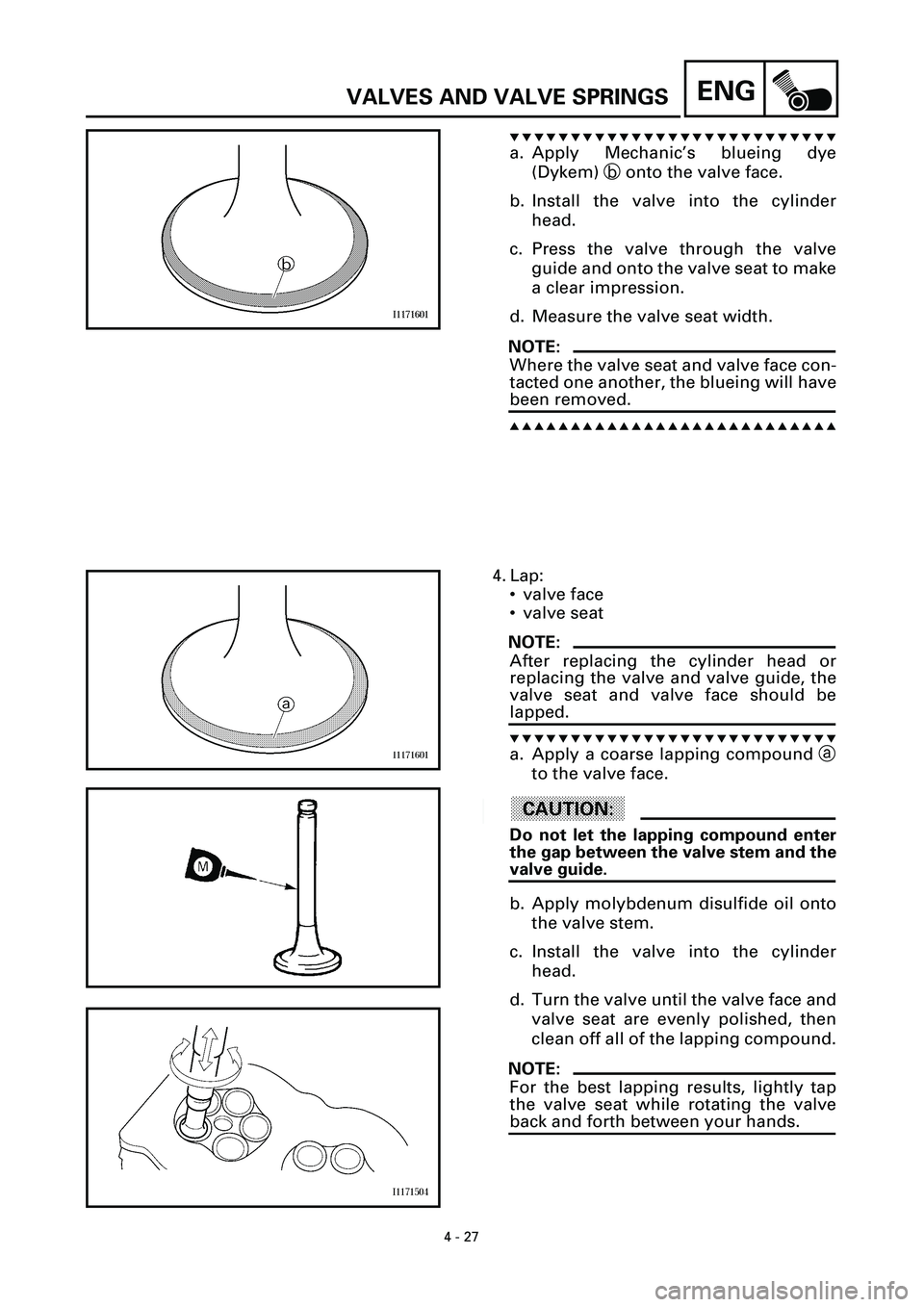
a. Apply Mechanic’s blueing dye
(Dykem) b onto the valve face.
b. Install the valve into the cylinder
head.
c. Press the valve through the valve
guide and onto the valve seat to make
a clear impression.
d. Measure the valve seat width.
NOTE:
Where the valve seat and valve face con-
tacted one another, the blueing will have
been removed.
s s s s s s s s s s s s s s s s s s s s s s s s s s s
4. Lap:
• valve face
• valve seat
NOTE:
After replacing the cylinder head or
replacing the valve and valve guide, the
valve seat and valve face should be
lapped.
t t t t t t t t t t t t t t t t t t t t t t t t t t t
a. Apply a coarse lapping compound a
to the valve face.
ACHTUNG:CAUTION:
Do not let the lapping compound enter
the gap between the valve stem and the
valve guide.
b. Apply molybdenum disulfide oil onto
the valve stem.
c. Install the valve into the cylinder
head.
d. Turn the valve until the valve face and
valve seat are evenly polished, then
clean off all of the lapping compound.
NOTE:
For the best lapping results, lightly tap
the valve seat while rotating the valve
back and forth between your hands.
Page 160 of 381

4 - 28
ENGVALVES AND VALVE SPRINGS
e. Apply a fine lapping compound to the
valve face and repeat the above
steps.
f. After every lapping procedure, be
sure to clean off all of the lapping
compound from the valve face and
valve seat.
g. Apply Mechanic’s blueing dye
(Dykem) b onto the valve face.
h. Install the valve into the cylinder
head.
i. Press the valve through the valve
guide and onto the valve seat to make
a clear impression.
j. Measure the valve seat width c
again. If the valve seat width is out of
specification, reface and lap the valve
seat.
s s s s s s s s s s s s s s s s s s s s s s s s s s s
EB403420
CHECKING THE VALVE SPRINGS
The following procedure applies to all of
the valve springs.
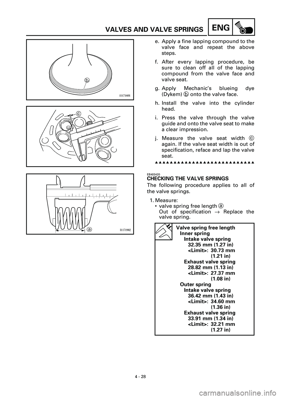
1. Measure:
• valve spring free length a
Out of specification ® Replace the
valve spring.
Valve spring free length
Inner spring
Intake valve spring
32.35 mm (1.27 in)
: 30.73 mm
(1.21 in)
Exhaust valve spring
28.82 mm (1.13 in)
: 27.37 mm
(1.08 in)
Outer spring
Intake valve spring
36.42 mm (1.43 in)
: 34.60 mm
(1.36 in)
Exhaust valve spring
33.91 mm (1.34 in)
: 32.21 mm
(1.27 in)
Page 201 of 381
4 - 69
ENGCONNECTING RODS AND PISTONS
c. Put a piece of Plastigaugeâ 1 on the
crankshaft pin.
d. Assemble the connecting rod halves.
NOTE:
• Do not move the connecting rod or
crankshaft until the clearance mea-
surement has been completed.
• Lubricate the bolt threads and nut
seats with MOLYKOTE
® G-n paste.
• Make sure that the “Y” mark c on the
connecting rod faces towards the left
side of the crankshaft.
• Make sure that the characters d on
both the connecting rod and connect-
ing rod cap are aligned.
e. Tighten the connecting rod nuts.
Refer to “INSTALLING THE PISTONS
AND CONNECTING RODS”.
f. Remove the connecting rod and big
end bearings.
Refer to “REMOVING THE CONNECT-
ING RODS AND PISTONS”.
g. Measure the compressed Plasti-
gauge
â width e on the crankshaft
pin.
If the crankshaft pin-to-big end bear-
ing clearance is out of specification,
select replacement big end bearings.
s s s s s s s s s s s s s s s s s s s s s s s s s s s
Page 209 of 381

4 - 77
ENGCRANKSHAFT
g. Remove the lower crankcase and the
crankshaft journal lower bearings.
h. Measure the compressed Plasti-
gauge
Ò width c on each crankshaft
journal.
If the clearance is out of specification,
select replacement crankshaft jour-
nal bearings.
s s s s s s s s s s s s s s s s s s s s s s s s s s s
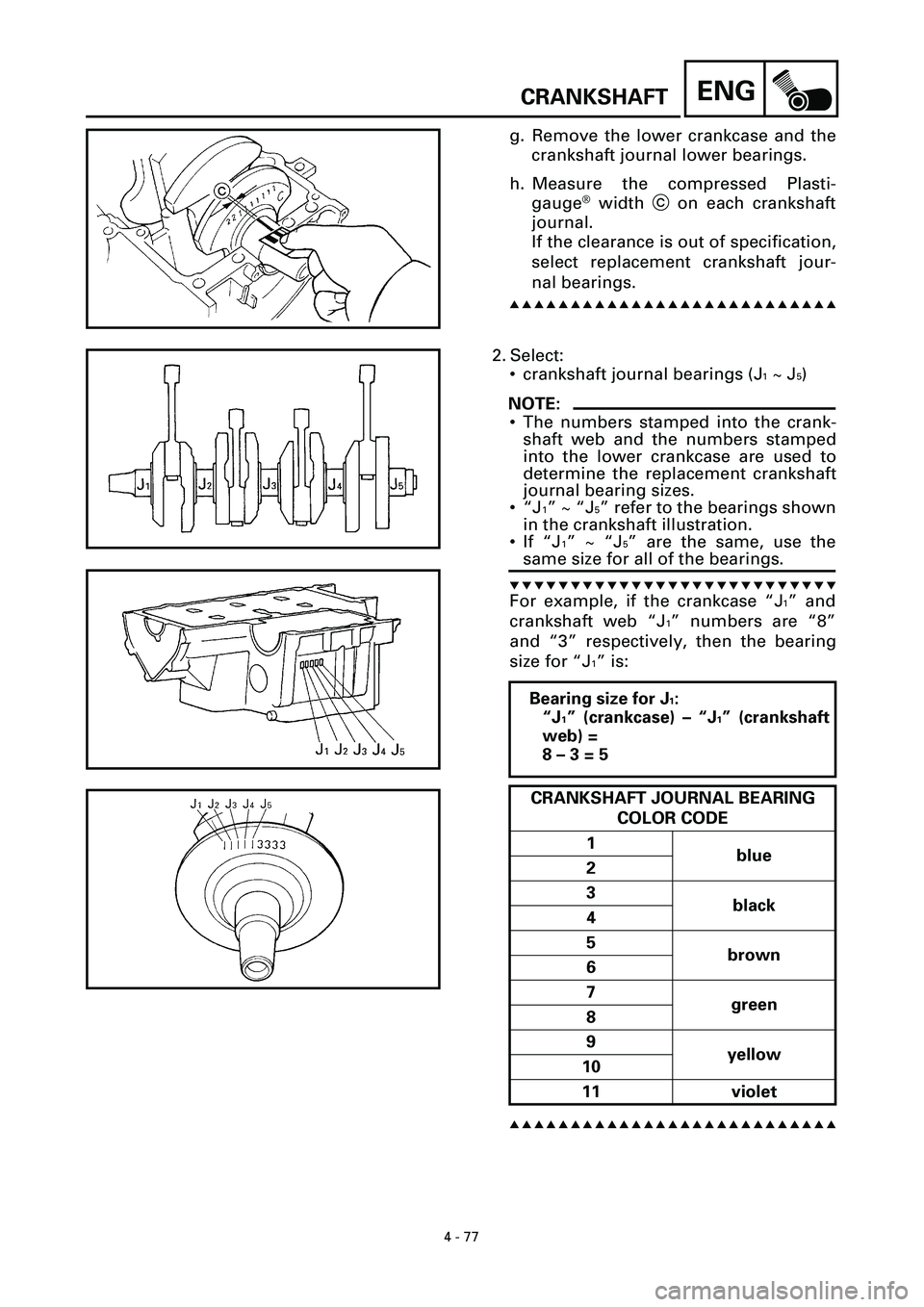
2. Select:
• crankshaft journal bearings (J
1 ~ J5)
NOTE:
• The numbers stamped into the crank-
shaft web and the numbers stamped
into the lower crankcase are used to
determine the replacement crankshaft
journal bearing sizes.
•“J
1” ~ “J5” refer to the bearings shown
in the crankshaft illustration.
• If “J
1” ~ “J5” are the same, use the
same size for all of the bearings.
t t t t t t t t t t t t t t t t t t t t t t t t t t t
For example, if the crankcase “J1” and
crankshaft web “J
1” numbers are “8”
and “3” respectively, then the bearing
size for “J
1” is:
s s s s s s s s s s s s s s s s s s s s s s s s s s s
Bearing size for J1:
“J
1” (crankcase) – “J1” (crankshaft
web) =
8 – 3 = 5
CRANKSHAFT JOURNAL BEARING
COLOR CODE
1
blue
2
3
black
4
5
brown
6
7
green
8
9
yellow
10
11 violet