Page 53 of 381

ELECTRICAL SPECIFICATIONSSPEC
2 - 15
ELECTRICAL SPECIFICATIONS
Item Standard Limit
System voltage12 V ----
Ignition system
Ignition system type C.D.I. ----
Ignition timing 5˚ BTDC at 1,100 r/min ----
Advanced timing 55˚ BTDC at 5,000 r/min ----
Advancer type Throttle position sensor and electrical ----
Pickup coil resistance/color 421 ~ 569 W / Gy–B ----
C.D.I. unit model (manufacturer) F8T19371 (MITSUBISHI) ----
Ignition coils
Model (manufacturer) F6T549 (MITSUBISHI) ----
Minimum ignition spark gap 6 mm (0.24 in) ----
Primary coil resistance 0.16 ~ 0.21 W ----
Secondary coil resistance 5.0 ~ 6.8 kW ----
Throttle position sensor standard
resistance4 ~ 6 kW----
Charging system
System type AC magneto ----
Model (manufacturer) F4T254 (MITSUBISHI) ----
Nominal output 14 V / 22.5 A at 5,000 r/min ----
Stator coil resistance 0.38 ~ 0.46 W at 20˚C (68˚F) ----
Rectifier/regulator
Regulator type Semiconductor-short circuit ----
Model SH650D-11 (SHINDENGEN) ----
No-load regulated voltage 14.1 ~ 14.9 V ----
Capacity 18 A ----
Withstand voltage 200 V ----
Battery
Battery type GT9B-4 ----
Battery voltage/capacity 12V / 8AH ----
Headlight typeHalogen bulb
Indicator light type ´ quantityLED ´ 5
Bulbs (voltage/wattage ´ quantity)
Headlight R. 12 V 60 W ´ 1 / L. 12 V 51 W ´ 1 ----
Auxiliary light 12 V 5 W ´ 2 ----
Tail/brake light 12 V 5 W / 21 W ´ 1 ----
Front turn signal light 12 V 21 W ´ 2 ----
Rear turn signal light 12 V 21 W ´ 2 ----
Meter light 12 V 1.4 W ´ 2 ----
Page 131 of 381
3 - 62
CHK
ADJ
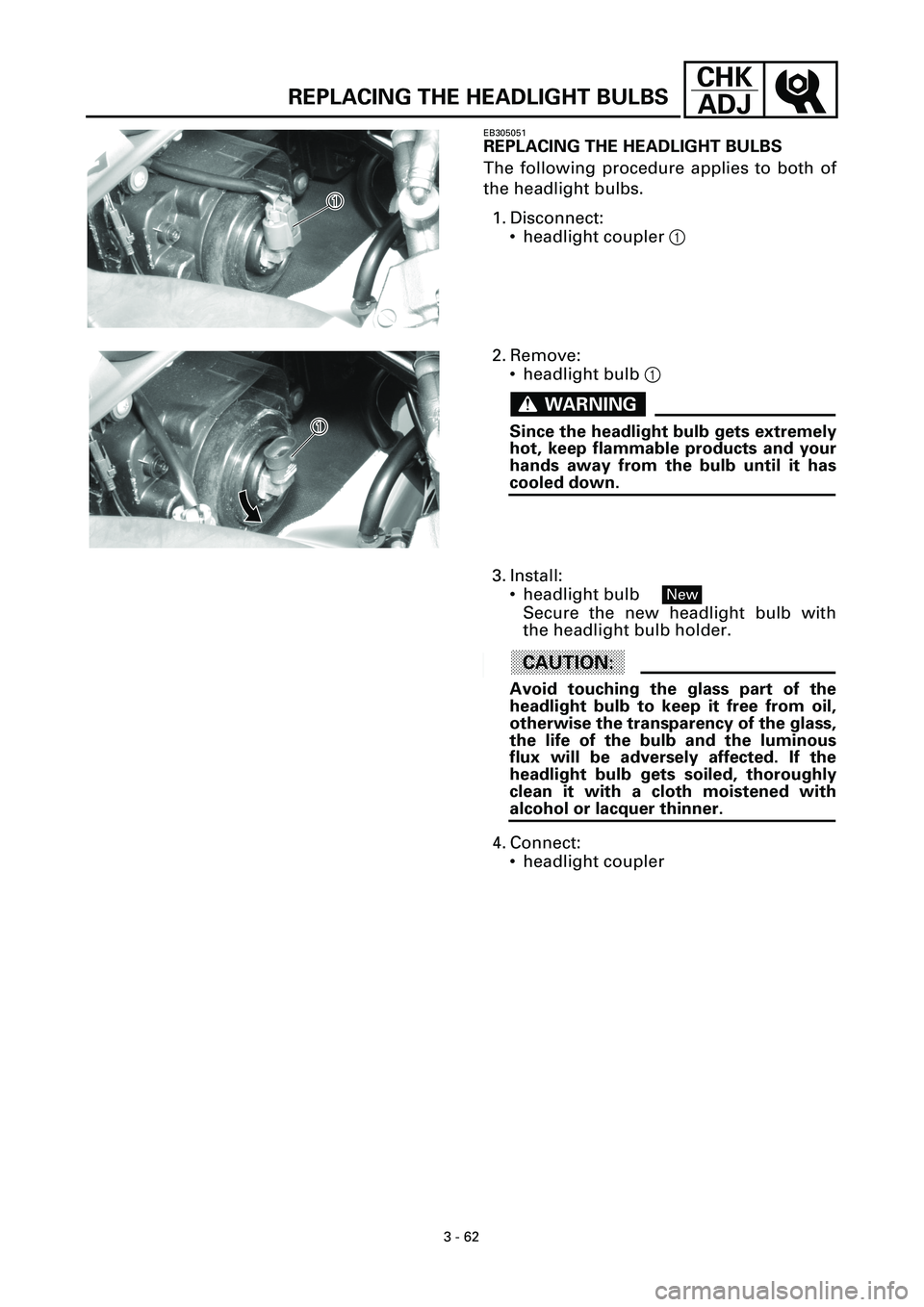
REPLACING THE HEADLIGHT BULBS
EB305051
REPLACING THE HEADLIGHT BULBS
The following procedure applies to both of
the headlight bulbs.
1. Disconnect:
• headlight coupler 1
1�
1�
2. Remove:
• headlight bulb 1
WARNINGWARNING
Since the headlight bulb gets extremely
hot, keep flammable products and your
hands away from the bulb until it has
cooled down.
1�
1�
3. Install:
• headlight bulb
Secure the new headlight bulb with
the headlight bulb holder.
ACHTUNG:CAUTION:
Avoid touching the glass part of the
headlight bulb to keep it free from oil,
otherwise the transparency of the glass,
the life of the bulb and the luminous
flux will be adversely affected. If the
headlight bulb gets soiled, thoroughly
clean it with a cloth moistened with
alcohol or lacquer thinner.
4. Connect:
• headlight coupler
New
Page 340 of 381

8 - 4
–+ELECCHECKING THE BULBS AND BULB SOCKETS
EB801020
CHECKING THE BULBS AND
BULB SOCKETS
Check each bulb and bulb socket for dam-
age or wear, proper connections, and also
for continuity between the terminals.
Damage/wear ® Repair or replace the
bulb, bulb socket or both.
Improperly connected ® Properly con-
nect.
Incorrect continuity reading ® Repair or
replace the bulb, bulb socket or both.
TYPES OF BULBS
The bulbs used on this motorcycle are
shown in the illustration on the left.
• Bulbs A and B are used for headlights
and usually use a bulb holder which must
be detached before removing the bulb.
The majority of these bulbs can be
removed from their respective socket by
turning them counterclockwise.
• Bulb C is used for turn signal and tail/
brake lights and can be removed from the
socket by pushing and turning the bulb
counterclockwise.
• Bulbs
D and E are used for meter and
indicator lights and can be removed from
their respective socket by carefully pulling
them out.
CHECKING THE CONDITION OF THE BULBS
The following procedure applies to all of
the bulbs.
1.Remove:
• bulb
Page 341 of 381

8 - 5
–+ELECCHECKING THE BULBS AND BULB SOCKETS
WARNINGWARNING
Since the headlight bulb gets extremely
hot, keep flammable products and your
hands away from the bulb until it has
cooled down.
CAUTION:
• Be sure to hold the socket firmly when
removing the bulb. Never pull the lead,
otherwise it may be pulled out of the ter-
minal in the coupler.
• Avoid touching the glass part of the head-
light bulb to keep it free from oil, other-
wise the transparency of the glass, the
life of the bulb and the luminous flux will
be adversely affected. If the headlight
bulb gets soiled, thoroughly clean it with
a cloth moistened with alcohol or lacquer
thinner.
2.Check:
• bulb (for continuity)
(with the pocket tester)
No continuity ® Replace.
NOTE:
Before checking for continuity, set the
pocket tester to “0” and to the “W ´ 1”
range.
t t t t t t t t t t t t t t t t t t t t t t t t t t t t
a. Connect the tester positive probe to ter-
minal 1 and the tester negative probe to
terminal 2, and check the continuity.
b. Connect the tester positive probe to ter-
minal 1 and the tester negative probe to
terminal 3, and check the continuity.
c. If either of the readings indicate no conti-
nuity, replace the bulb.
s s s s s s s s s s s s s s s s s s s s s s s s s s s s
Pocket tester
90890-03112
Page 356 of 381

8 - 20
–+ELECLIGHTING SYSTEM
TROUBLESHOOTING
C0NTINUITYOK
C0NTINUITYOK
C0NTINUITYOK
C0NTINUITYOK
C0NTINUITYOK
C0NTINUITYOK
C0NTINUITYOK
C0NTINUITYOK
NOTE:
• Before troubleshooting, remove the following part(-s):
1) bottom cowling
2) front cowling
3) rear cowling
• Troubleshoot with the following special tool(-s).
Any of the following fail to light: headlight, high beam indicator light, taillight, auxiliary light
or meter light.
Check the main and headlight
fuses for continuity.Replace.
Check the condition of the bat-
tery.Recharge or replace.
Check the bulbs and bulb sockets. Replace.
Check the LED’s of the indicator
light.Replace the meter assembly.
Check the main switch. Replace.
Check the lights switch. Replace the left handlebar switch.
Check the dimmer switch. Replace the left handlebar switch.
Check the pass switch. Replace the left handlebar switch.
Check the entire lighting sys-
tem’s wiring.Repair or replace.
Pocket tester
90890-03112
No good
No good
No good
No good
No good
No good
No good
No good
No good