Page 47 of 381

ENGINE SPECIFICATIONS
SPEC
2 - 9
Oil ring
Dimensions (B
´
T) 1.5
´
2.5 mm (0.059
´
0.098 in) ----
End gap (installed) 0.1 ~ 0.3 mm (0.004 ~ 0.012 in) ----
Connecting rods
Crankshaft pin-to-big end bearing
clearance0.058 ~ 0.078 mm (0.0023 ~ 0.0031 in) ----
Bearing color code 2 = Blue, 3·4 = Black, 5·6 = Brown,
7·8 = Green, 9 = Yellow----
Crankshaft
Width A 54.4 ~ 56.0 mm (2.142 ~ 2.205 in) ----
Width B 292.8 ~ 294.0 mm (11.53 ~ 11.57 in) ----
Maximum runout C 0.035 mm
(0.0014 in)
Big end side clearance D 0.16 ~ 0.26 mm (0.006 ~ 0.010 in) ----
Crankshaft journal-to-crankshaft
journal bearing clearance0.036 ~ 0.056 mm (0.0014 ~ 0.0022 in) ----
Bearing color code1·2 = Blue, 3·4 = Black, 5·6 = Brown, 7·8 =
Green, 9·10 = Yellow, 11 = Violet----
Clutch
Clutch type Wet, multiple disc ----
Clutch release method Hydraulic inner push ----
Operation Left-hand operation ----
Recommended fluid Brake fluid DOT4 ----
Friction plates #1
Thickness 2.9 ~ 3.1 mm (0.114 ~ 0.122 in) 2.8 mm
(0.110 in)
Plate quantity 8 ----
Friction plate #2
Thickness 3.7 ~ 3.9 mm (0.146 ~ 0.154 in) 3.6 mm
(0.142 in)
Plate quantity 1 ----Item Standard Limit
B
T
D
FCCC
A
B
E
Page 144 of 381
4 - 12
ENGCAMSHAFTS
EB401401
CHECKING THE CAMSHAFTS
1. Check:
• camshaft lobes
Blue discoloration/pitting/scratches ®
Replace the camshaft.
2. Measure:
• camshaft lobe dimensions a and b
Out of specification ® Replace the
camshaft.
Camshaft lobe dimensions
limit
Intake camshaft
a 33.31 mm (1.3114 in)
b 24.90 mm (0.9803 in)
Exhaust camshaft
a 32.95 mm (1.2972 in)
b 24.936 mm (0.9817 in)
3. Measure:
• camshaft runout
Out of specification ® Replace.
Maximum camshaft runout
0.03 mm (0.0012 in)
4. Measure:
• camshaft journal-to-camshaft cap
clearance
Out of specification ® Measure the
camshaft journal diameter.
Camshaft journal-to-camshaft
cap clearance
0.035 ~ 0.069 mm
(0.0014 ~ 0.0027 in)
Page 159 of 381

4 - 27
ENGVALVES AND VALVE SPRINGS
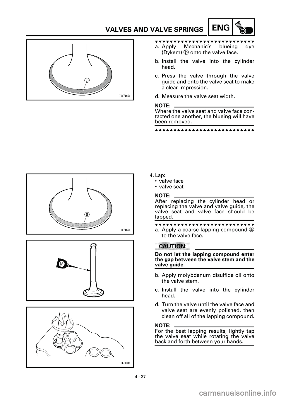
t t t t t t t t t t t t t t t t t t t t t t t t t t t
a. Apply Mechanic’s blueing dye
(Dykem) b onto the valve face.
b. Install the valve into the cylinder
head.
c. Press the valve through the valve
guide and onto the valve seat to make
a clear impression.
d. Measure the valve seat width.
NOTE:
Where the valve seat and valve face con-
tacted one another, the blueing will have
been removed.
s s s s s s s s s s s s s s s s s s s s s s s s s s s
4. Lap:
• valve face
• valve seat
NOTE:
After replacing the cylinder head or
replacing the valve and valve guide, the
valve seat and valve face should be
lapped.
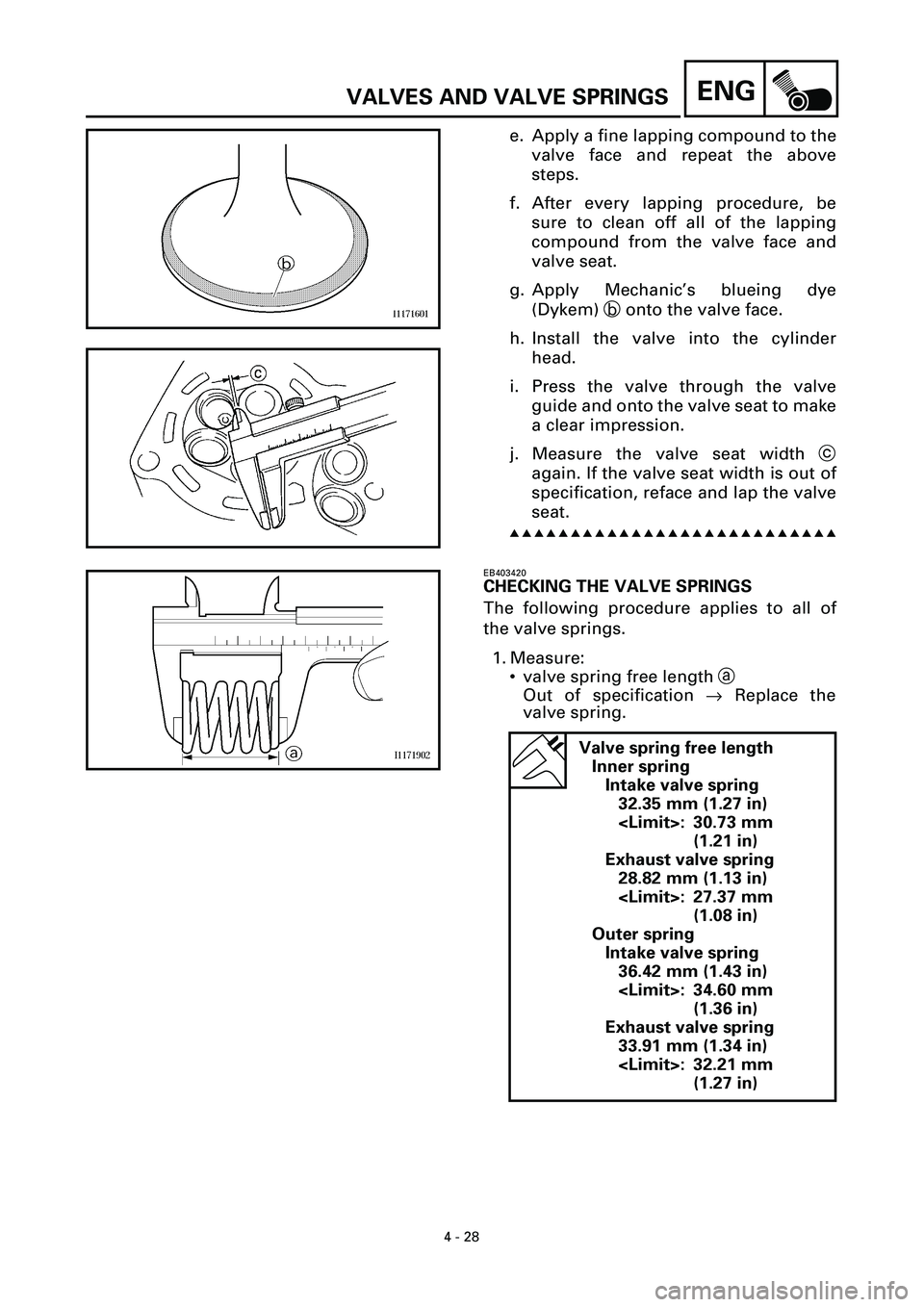
t t t t t t t t t t t t t t t t t t t t t t t t t t t
a. Apply a coarse lapping compound a
to the valve face.
ACHTUNG:CAUTION:
Do not let the lapping compound enter
the gap between the valve stem and the
valve guide.
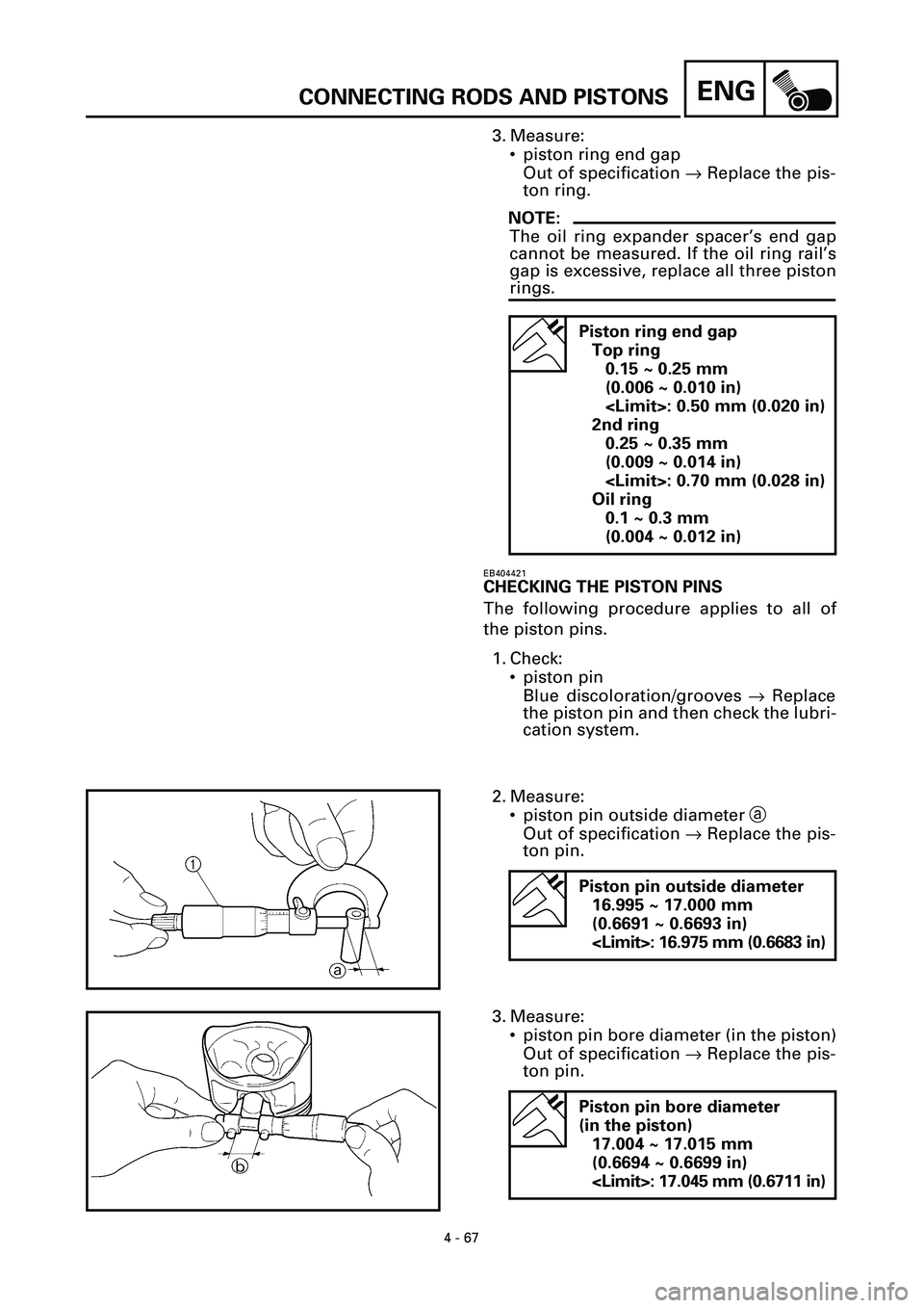
b. Apply molybdenum disulfide oil onto
the valve stem.
c. Install the valve into the cylinder
head.
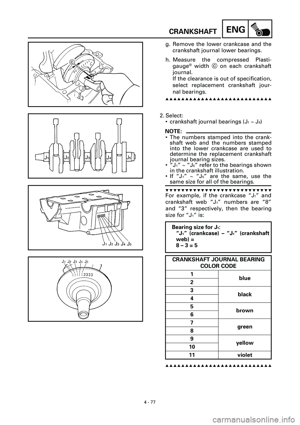
d. Turn the valve until the valve face and
valve seat are evenly polished, then
clean off all of the lapping compound.
NOTE:
For the best lapping results, lightly tap
the valve seat while rotating the valve
back and forth between your hands.
Page 160 of 381

4 - 28
ENGVALVES AND VALVE SPRINGS
e. Apply a fine lapping compound to the
valve face and repeat the above
steps.
f. After every lapping procedure, be
sure to clean off all of the lapping
compound from the valve face and
valve seat.
g. Apply Mechanic’s blueing dye
(Dykem) b onto the valve face.
h. Install the valve into the cylinder
head.
i. Press the valve through the valve
guide and onto the valve seat to make
a clear impression.
j. Measure the valve seat width c
again. If the valve seat width is out of
specification, reface and lap the valve
seat.
s s s s s s s s s s s s s s s s s s s s s s s s s s s
EB403420
CHECKING THE VALVE SPRINGS
The following procedure applies to all of
the valve springs.
1. Measure:
• valve spring free length a
Out of specification ® Replace the
valve spring.
Valve spring free length
Inner spring
Intake valve spring
32.35 mm (1.27 in)
: 30.73 mm
(1.21 in)
Exhaust valve spring
28.82 mm (1.13 in)
: 27.37 mm
(1.08 in)
Outer spring
Intake valve spring
36.42 mm (1.43 in)
: 34.60 mm
(1.36 in)
Exhaust valve spring
33.91 mm (1.34 in)
: 32.21 mm
(1.27 in)
Page 199 of 381

4 - 67
ENGCONNECTING RODS AND PISTONS
3. Measure:
• piston ring end gap
Out of specification ® Replace the pis-
ton ring.
NOTE:
The oil ring expander spacer’s end gap
cannot be measured. If the oil ring rail’s
gap is excessive, replace all three piston
rings.
Piston ring end gap
Top ring
0.15 ~ 0.25 mm
(0.006 ~ 0.010 in)
: 0.50 mm (0.020 in)
2nd ring
0.25 ~ 0.35 mm
(0.009 ~ 0.014 in)
: 0.70 mm (0.028 in)
Oil ring
0.1 ~ 0.3 mm
(0.004 ~ 0.012 in)
EB404421
CHECKING THE PISTON PINS
The following procedure applies to all of
the piston pins.
1. Check:
• piston pin
Blue discoloration/grooves ® Replace
the piston pin and then check the lubri-
cation system.
2. Measure:
• piston pin outside diameter a
Out of specification ® Replace the pis-
ton pin.
Piston pin outside diameter
16.995 ~ 17.000 mm
(0.6691 ~ 0.6693 in)
: 16.975 mm (0.6683 in)
3. Measure:
• piston pin bore diameter (in the piston)
Out of specification ® Replace the pis-
ton pin.
Piston pin bore diameter
(in the piston)
17.004 ~ 17.015 mm
(0.6694 ~ 0.6699 in)
: 17.045 mm (0.6711 in)
Page 202 of 381
4 - 70
ENGCONNECTING RODS AND PISTONS
2. Select:
• big end bearings (“P
1”~ “P4”)
NOTE:
• The numbers stamped into the crank-
shaft web and the numbers on the
connecting rods are used to determine
the replacement big end bearing sizes.
•“P
1”~“P4” refer to the bearings shown
in the crankshaft illustration.
t t t t t t t t t t t t t t t t t t t t t t t t t t t
For example, if the connecting rod
“P
1” and the crankshaft web “P1” num-
bers are “9” and “3” respectively, then
the bearing size for “P
1” is:
s s s s s s s s s s s s s s s s s s s s s s s s s s s
“P1” (connecting rod) – “P1” (crank-
shaft) =
9 – 3 = 6
BIG END BEARING COLOR CODE
2 blue
3
black
4
5
brown
6
7
green
8
9 yellow
EB404704
INSTALLING THE PISTONS AND
CONNECTING RODS
The following procedure applies to all of
the pistons and cylinders.
1. Install:
• top ring
• 2nd ring
• oil ring
NOTE:
Be sure to install the piston rings so that
the manufacturer’s marks or numbers
face up.
Page 209 of 381

4 - 77
ENGCRANKSHAFT
g. Remove the lower crankcase and the
crankshaft journal lower bearings.
h. Measure the compressed Plasti-
gauge
Ò width c on each crankshaft
journal.
If the clearance is out of specification,
select replacement crankshaft jour-
nal bearings.
s s s s s s s s s s s s s s s s s s s s s s s s s s s
2. Select:
• crankshaft journal bearings (J
1 ~ J5)
NOTE:
• The numbers stamped into the crank-
shaft web and the numbers stamped
into the lower crankcase are used to
determine the replacement crankshaft
journal bearing sizes.
•“J
1” ~ “J5” refer to the bearings shown
in the crankshaft illustration.
• If “J
1” ~ “J5” are the same, use the
same size for all of the bearings.
t t t t t t t t t t t t t t t t t t t t t t t t t t t
For example, if the crankcase “J1” and
crankshaft web “J
1” numbers are “8”
and “3” respectively, then the bearing
size for “J
1” is:
s s s s s s s s s s s s s s s s s s s s s s s s s s s
Bearing size for J1:
“J
1” (crankcase) – “J1” (crankshaft
web) =
8 – 3 = 5
CRANKSHAFT JOURNAL BEARING
COLOR CODE
1
blue
2
3
black
4
5
brown
6
7
green
8
9
yellow
10
11 violet
Page 218 of 381

4 - 86
ENGTRANSMISSION
3. Check:
• shift fork movement
(along the shift fork guide bar)
Rough movement ® Replace the shift
fork(-s) and shift fork guide bar as a
set.
EB413410
CHECKING THE SHIFT DRUM ASSEMBLY
1. Check:
• shift drum grooves
Damage/scratches/wear ® Replace the
shift drum assembly.
• shift drum segment 1
Damage/wear ® Replace the shift
drum assembly.
• shift drum bearing 2
Damage/pitting ® Replace the shift
drum assembly.
EB413422
CHECKING THE TRANSMISSION
1. Measure:
• main axle runout
(with a centering device and dial
gauge 1)
Out of specification ® Replace the
main axle.
Maximum main axle runout
0.08 mm (0.003 in)
2. Measure:
• drive axle runout
(with a centering device and dial
gauge 1)
Out of specification ® Replace the
drive axle.
Maximum drive axle runout
0.08 mm (0.003 in)
3. Check:
• transmission gears
Blue discoloration/pitting/wear ®
Replace the defective gear(-s).
• transmission gear dogs
Cracks/damage/rounded edges ®
Replace the defective gear(-s).