Page 1084 of 4592
BR0BT±03
W03274
Rear Speed Sensor
N´m (kgf´cm, ft´lbf): Specified torque
5.4 (55, 48 in.´lbf)
7.8 (80, 69 in.´lbf)
5.4 (55, 48 in.´lbf)
BR±70
± BRAKEREAR SPEED SENSOR
2093 Author�: Date�:
REAR SPEED SENSOR
COMPONENTS
Page 1085 of 4592
BR0BU±03
R00330
W04508
± BRAKEREAR SPEED SENSOR
BR±71
2094 Author�: Date�:
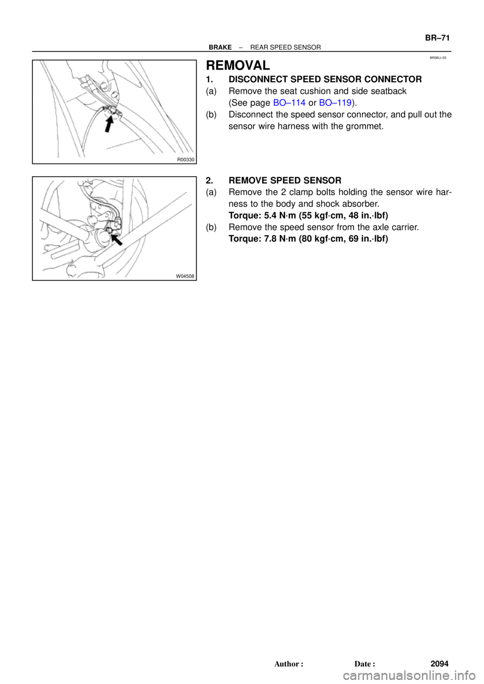
REMOVAL
1. DISCONNECT SPEED SENSOR CONNECTOR
(a) Remove the seat cushion and side seatback
(See page BO±114 or BO±119).
(b) Disconnect the speed sensor connector, and pull out the
sensor wire harness with the grommet.
2. REMOVE SPEED SENSOR
(a) Remove the 2 clamp bolts holding the sensor wire har-
ness to the body and shock absorber.
Torque: 5.4 N´m (55 kgf´cm, 48 in.´lbf)
(b) Remove the speed sensor from the axle carrier.
Torque: 7.8 N´m (80 kgf´cm, 69 in.´lbf)
Page 1086 of 4592
BR0BV±02
BR±72
± BRAKEREAR SPEED SENSOR
2095 Author�: Date�:
INSTALLATION
Installation is in the reverse order of removal (See page BR±71).
HINT:
After installation, check the speed sensor signal (See page DI±493, DI±539).
Page 1144 of 4592
S05939
No.2 Timing Belt
Cover
No.1 Timing Belt
Cover
Crankshaft
Pulley
No.2 Idler Pulley
Generator Drive Belt
Adjusting Bar
Wire Clamp
Crankshaft Position Sensor
Connector* Gasket
No.1 Idler Pulley
Tension Spring
� O±Ring
Water PumpWater PumpTiming Belt
Timing Belt Guide
Lower
Radiator
Hose Water Pump and
Water Pump Cover
Assembly High±Tension Cord Generator Wire
� Gasket Wire Clamp
Wire Clamp
Wire ClampWire Clamp Wire
Clamp
* GasketGenerator Connector
Generator
Spark Plug
� O±Ring
� Gasket
N´m (kgf´cm, ft´lbf): Specified torque
� Non±reusable part
108 (1,100, 80)18 (180,13)
42 (425,31)
42 (425,31)
* Replace only if damagedCover CO±4
± COOLING (5S±FE)WATER PUMP
1578 Author�: Date�:
Page 1145 of 4592
CO069±04
S05599
S05924
S05963
1
2
3
± COOLING (5S±FE)WATER PUMP
CO±5
1579 Author�: Date�:
REMOVAL
1. DRAIN ENGINE COOLANT
2. REMOVE TIMING BELT (See page EM±17)
3. DISCONNECT LOWER RADIATOR HOSE FROM WA-
TER OUTLET
4. REMOVE TIMING BELT TENSION SPRING
Loosen the No.1 idler pulley bolt, and remove the tension
spring.
5. REMOVE NO.2 IDLER PULLEY
Remove the bolt and idler pulley.
6. w/ Oil Cooler:
REMOVE A/C COMPRESSOR (See page EM±69)
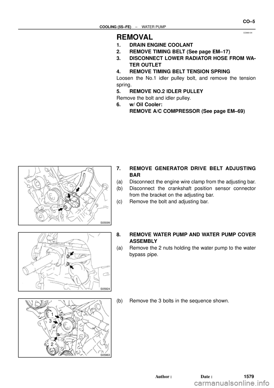
7. REMOVE GENERATOR DRIVE BELT ADJUSTING
BAR
(a) Disconnect the engine wire clamp from the adjusting bar.
(b) Disconnect the crankshaft position sensor connector
from the bracket on the adjusting bar.
(c) Remove the bolt and adjusting bar.
8. REMOVE WATER PUMP AND WATER PUMP COVER
ASSEMBLY
(a) Remove the 2 nuts holding the water pump to the water
bypass pipe.
(b) Remove the 3 bolts in the sequence shown.
Page 1148 of 4592
WATER PUMP
1582 Author�: Date�:
INSTALLATION
1. INSTALL WATER PUMP TO WATER PUMP COVER
Install a new gasket and the")
CO06B±03
N00918
S06015
Connect
Z19283
1
3
2
S05924
S05599
CO±8
± COOLING (5S±FE)WATER PUMP
1582 Author�: Date�:
INSTALLATION
1. INSTALL WATER PUMP TO WATER PUMP COVER
Install a new gasket and the water pump with the 3 bolts.
Torque: 8.8 N´m (90 kgf´cm, 78 in.´lbf)
2. INSTALL WATER PUMP AND WATER PUMP COVER
ASSEMBLY
(a) Install new O±ring and gasket to water pump cover.
(b) Install a new O±ring to the water bypass pipe.
(c) Apply soapy water to the O±ring on the water bypass
pipe.
(d) Connect the water pump cover to the water bypass pipe.
Do not install the nuts yet.
(e) Install the water pump with the 3 bolts. Tighten the bolts
in the sequence shown.
Torque: 8.8 N´m (90 kgf´cm, 78 in.´lbf)
(f) Install the 2 nuts holding the water pump cover to the wa-
ter bypass pipe.
Torque: 9.3 N´m (95 kgf´cm, 82 in.´lbf)
3. INSTALL GENERATOR DRIVE BELT ADJUSTING BAR
(a) Install the adjusting bar with the bolt.
Torque: 22 N´m (224 kgf´cm, 16 ft´lbf)
(b) Install the engine wire clamp to the adjusting bar.
(c) Install the crankshaft position sensor connector to the
bracket on the adjusting bar.
4. w/ Oil Cooler:
INSTALL A/C COMPRESSOR (See page EM±75)
5. INSTALL NO.2 IDLER PULLEY (See page EM±23)
Page 1226 of 4592

249 Author�: Date�:
7. ENGINE OPERATING CONDITION
NOTICE:
The values given below for ºNormal Conditionº are representative values, so a vehicle may still be
norm")
DI±14
± DIAGNOSTICSENGINE (5S±FE)
249 Author�: Date�:
7. ENGINE OPERATING CONDITION
NOTICE:
The values given below for ºNormal Conditionº are representative values, so a vehicle may still be
normal even if its value varies from those listed here. So do not decide whether a part is faulty or
not solely according to the ºNormal Conditionº here.
(a) CARB mandated signals.
TOYOTA hand±held tester displayMeasurement ItemNormal Condition*1
FUEL SYS #1
Fuel System Bank 1
OPEN: Air±fuel ratio feedback stopped
CLOSED: Air±fuel ratio feedback operating
Idling after warming up: CLOSED
CALC LOAD
Calculator Load:
Current intake air volume as a proportion of max.
intake air volumeIdling: 19.7 ~ 50.4 %
Racing without load (2,500rpm): 16.8 ~ 47.4 %
COOLANT TEMP.Engine Coolant Temp. Sensor ValueAfter warming up: 80 ~ 95°C (176 ~ 203°F)
SHORT FT #1Short±term Fuel Trim Bank 10 ± 20 %
LONG FT #1Long±term Fuel Trim Bank 10 ± 20 %
ENGINE SPDEngine SpeedIdling: 650 ~ 750 rpm
VEHICLE SPDVehicle SpeedVehicle Stopped: 0 km/h (0 mph)
IGN ADVANCEIgnition Advance:
Ignition Timing of Cylinder No. 1Idling: BTDC 0 ~ 10°
INTAKE AIRIntake Air Temp. Sensor ValueEquivalent to Ambient Temp.
MAPAbsolute Pressure inside Intake Manifold
Idling: 20 ~ 51 kPa
Racing without load (2,500 rpm):
17 ~ 48 kPa
THROTTLE POS
Voltage Output of Throttle Position Sensor
Calculated as a percentage:
0 V "0%, 5 V "100 %Throttle Fully Closed: 6 ~ 16 %
Throttle Fully Open: 64 ~ 98 %
O2S B1, S1Voltage Output of Heated Oxygen Sensor
Bank 1 Sensor 1Idling: 0.1 ~ 0.9 V (0.56 ~ 0.76 V *2)
O2FT B1, S1
Heated Oxygen Sensor Fuel Trim Bank 1
Sensor 1
(Same as SHORT FT #1)
0 ± 20 %
A/FS B1, S1 *3Voltage Output of A/F SensorIdling: 2.8 ~ 3.8 V
A/FFT B1, S1 *3A/F Sensor Fuel Trim (Same as SHORT FT #1)0 ± 20 %
O2S B1, S2Voltage Output of Heated Oxygen Sensor
Bank 1 Sensor 2Driving at 50 km/h (31 mph): 0.05 ~ 0.95 V
*1: If no conditions are specifically stated for ºldlingº, it means the shift lever is at N or P position, the A/C
switch is OFF and all accessory switches are OFF.
*2: Only for California Specification vehicles, when you use the OBD II scan tool (excluding TOYOTA hand±
held tester).
*3: Only for California Specification vehicles, when you use the TOYOTA hand±held tester.
Page 1227 of 4592

DI±15
250 Author�: Date�:
(b) TOYOTA Enhanced Signals.
TOYOTA hand±held tester displayMeasurement ItemNormal Condition*1
MISFIRE RPMEngine RPM for first misfire rangeMi")
± DIAGNOSTICSENGINE (5S±FE)
DI±15
250 Author�: Date�:
(b) TOYOTA Enhanced Signals.
TOYOTA hand±held tester displayMeasurement ItemNormal Condition*1
MISFIRE RPMEngine RPM for first misfire rangeMisfire 0: 0 rpm
MISFIRE LOADEngine load for first misfire rangeMisfire 0: 0 g/r
INJECTORFuel injection time for cylinder No.1Idling: 2.9 ~ 5.1 ms
IAC DUTY RATIOIntake Air Control Valve Duty Ratio
Opening ratio rotary solenoid type IAC valveIdling: 25 ~ 62 %
STARTER SIGStarter SignalCranking: ON
CTP SIGClosed Throttle Position SignalThrottle fully closed: ON
A/C SIGA/C Switch SignalA/C ON: ON
PNP SIGPark/Neutral Position Switch SignalP or N position: ON
ELECTCL LOAD SIGElectrical Load SignalDefogger S/W ON: ON
STOP LIGHT SWStop Light Switch SignalStop light switch ON: ON
PS OIL PRESS SWPower Steering Oil Pressure Switch SignalTurn steering wheel: ON
FC IDLFuel Cut Idle: Fuel cut when throttle valve fully
closed, during decelerationFuel cut operating: ON
FC TAUFuel Cut TAU: Fuel cut during very light loadFuel cut operating: ON
CYL#1, CYL#2, CYL#3, CYL#4Abnormal revolution variation for each cylinder0 %
IGNITIONTotal number of ignition for every 1,000 revolu-
tions0 ~ 2,000 rpm
EGR SYSTEMEGR system operating conditionIdling: OFF
FUEL PUMPFuel Pump SignalIdling: ON
A/C CUT SIGA/C Cut SignalA/C S/W OFF: ON
A/C MAG CLUTCHA/C Switch SignalA/C ON: ON
EVAP (PURGE) VSVEVAP VSV SignalVSV operating: Avove 30 %
VAPOR PRESS VSVVapor Pressure VSV SignalVSV operating: ON
TOTAL FT B1Total Fuel Trim Bank 1: Average value for fuel
trim system of bank 1Idling: 0.8 ~ 1.2 V
O2 LR B1, S1 *2
Heated Oxygen Sensor Lean Rich Bank 1 Sen-
sor 1: Response time for oxygen sensor output to
switch from lean to rich
Idling after warming up: 0 ~ 1,000 msec.
O2 RL B1, S1 *2
Heated Oxygen Sensor Rich Lean Bank 1 Sen-
sor 1: Response time for oxygen sensor output to
switch from rich to lean
Idling after warming up: 0 ~ 1,000 msec.
*1: If no conditions are specifically stated for ºldlingº, it means the shift lever is at N or P position, the A/C
switch is OFF and all accessory switches are OFF.
*2: Except California Specification vehicles.