Page 617 of 4592
BE0AE±02
Z19048
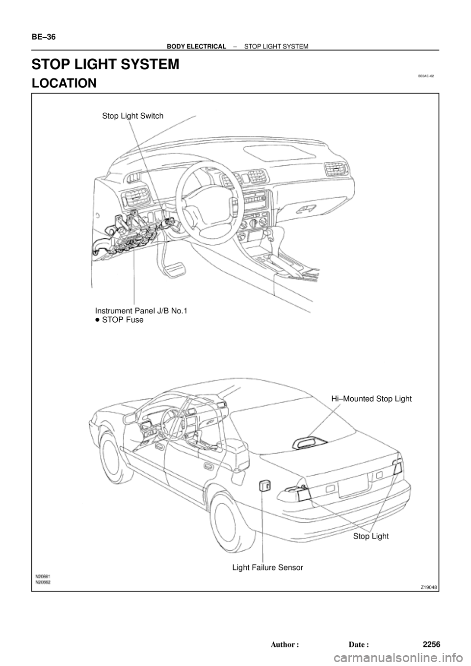
Stop Light Switch
Instrument Panel J/B No.1
� STOP Fuse
Hi±Mounted Stop Light
Stop Light
Light Failure Sensor BE±36
± BODY ELECTRICALSTOP LIGHT SYSTEM
2256 Author�: Date�:
STOP LIGHT SYSTEM
LOCATION
Page 626 of 4592
Z19055
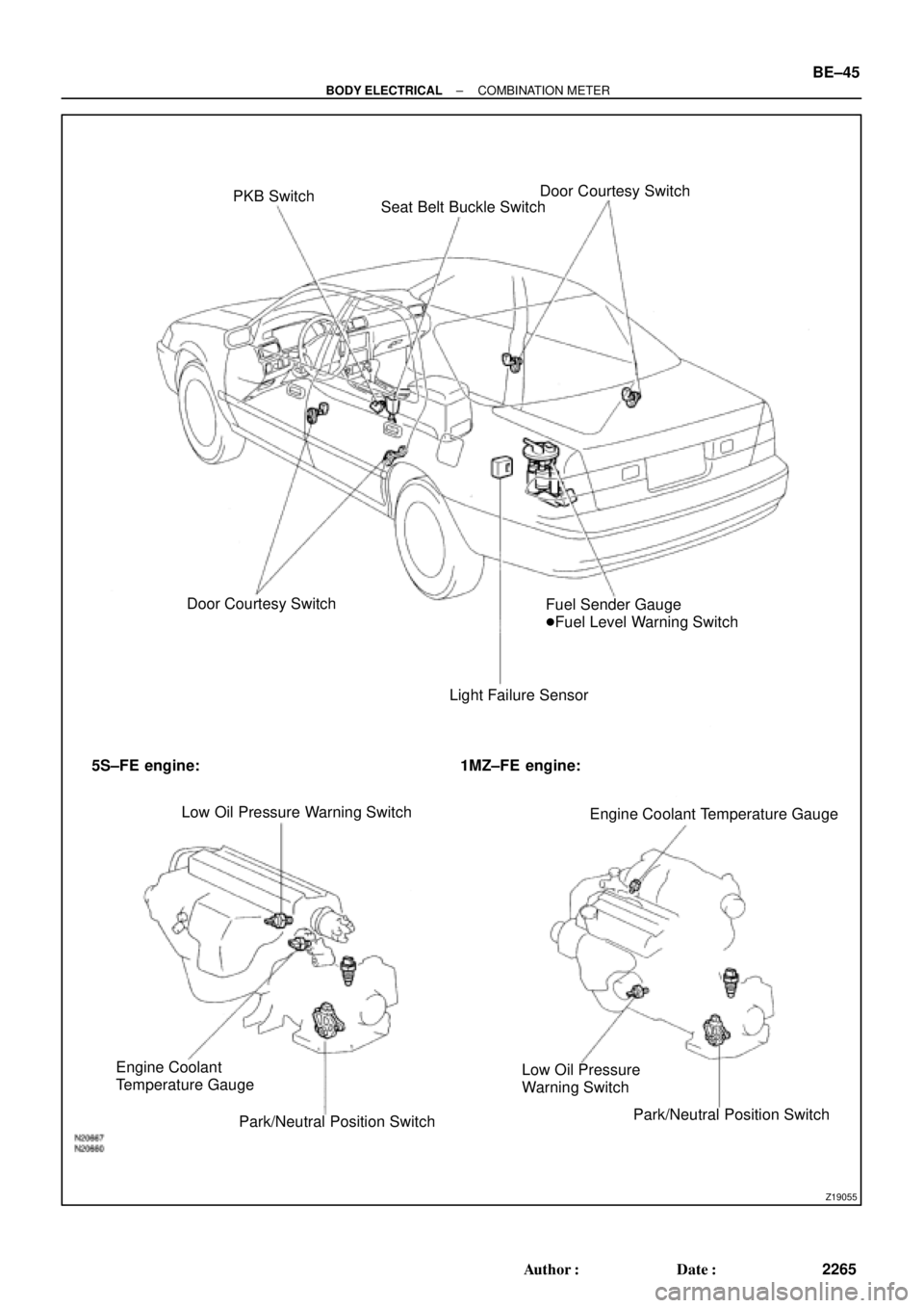
PKB Switch
Seat Belt Buckle SwitchDoor Courtesy Switch
Door Courtesy Switch
Light Failure SensorFuel Sender Gauge
�Fuel Level Warning Switch
5S±FE engine: 1MZ±FE engine:
Low Oil Pressure Warning Switch
Engine Coolant Temperature Gauge
Engine Coolant
Temperature Gauge
Park/Neutral Position SwitchLow Oil Pressure
Warning Switch
Park/Neutral Position Switch
± BODY ELECTRICALCOMBINATION METER
BE±45
2265 Author�: Date�:
Page 627 of 4592

BE0AJ±03
Z18937
Connector ºAº Connector ºBº Connector ºCº
Connector ºAº
Connector ºBº
Connector ºCº
J±13±1±A J±16±1 J±13±1
1 2 3 4 5 6 7 8 9 10 11 12 1314 15 16 1 234 56 78 910111213 1 23456 78910111213
C7
C5
A2 B3
A1
C8
B15
C6
B6
A4
C4
B5
C10 B14
A13
B2
C1
B1
C9
A6
A11
A7
A10
A8
A9
C13
B8
B11
B12A5
C11
B4
B16 C2
A12
A3
B7
C3
C12
B9
B10
B13 F
E
T
S
ODOMETER
Fuel Level Warning
Seat Belt Warning
ABS Warning
Low Oil Pressure Warning
Cruise Control Indicator
Malfunction Indicator
O/D OFF Indicator
Light Failure Warning
Brake Warning
SLIP Indicator
TRAC Indicator
Washer Level Warning
Discharge Warning
Right Turn Indicator
Left Turn Indicator
Security Indicator
L
2
D
N
R
P
Illumination
Hi±Beam Indicator
Open Door Warning
SRS Warning
: Fuel Gauge
: Engine Coolant Temperature Gauge
: Tachometer
: Speedometer
No.
A
B
C1
2
3
4
5
6
7 8
9
10
11
12 13
14
15
16
2 3
4
5
6
7 8
9
10
11 12
131
2
3
4 5
6
7
8
9
10
11
12
13
F
E
T
SEngine coolant temperature sender gauge
Ground
Light failure sensor
Integration relay
Traction ECU
Park/neutral position switch (A/T)
O/D OFF switch (A/T)
IGN fuse
Turn signal switch
ST relay
Fuel sender gauge
Generator
Oil pressure switch
Fuel sender gauge
Parking brake switch and brake fluid level warning switch
Headlight dimmer switch
Headlight dimmer switch
Door courtesy switch
DOME fuse
ECU±B fuse
Airbag sensor assembly
ECM
No.1 Vehicle speed sensor Ground
Turn signal switch ECM
Traction ECU
ABS ECU
Ground No.1 Vehicle speed sensor
GAUGE fuse
Igniter
Security ECU
Cruise control ECU
Washer fluid level warning switch
Light control rheostat
TAIL fuse Park/neutral position switch (A/T) Park/neutral position switch (A/T) Park/neutral position switch (A/T) Park/neutral position switch (A/T)
Park/neutral position switch (A/T)Wire Harness Side
Bulb Check
Relay
N20107 N201081
BE±46
± BODY ELECTRICALCOMBINATION METER
2266 Author�: Date�:
CIRCUIT
Page 628 of 4592

BE0AK±03
N02332
1
2 3
± BODY ELECTRICALCOMBINATION METER
BE±47
2267 Author�: Date�:
INSPECTION
1. INSPECT SPEEDOMETER ON±VEHICLE
Using a speedometer tester, inspect the speedometer for allow-
able indication error and check the operation of the odometer.
HINT:
Tire wear and tire over or under inflation will increase the indica-
tion error.
If error is excessive, replace the speedometer.
USA (mph)CANADA (km/h)
Standard indication Allowable rangeStandard indication Allowable range
20 18 ± 24 20 17 ± 24
40 38 ± 44 40 38 ± 46
60 56 ± 66 60 57.5 ± 67
80 78 ± 88 80 77 ± 88
100 98 ± 110 100 96 ± 109
120 118 ± 132 120 115 ± 130
140 134 ± 151.5
160 153 ± 173
2. INSPECT VEHICLE SPEED SENSOR OPERATION
(a) Connect the positive (+) lead from the battery to terminal
1 and negative (±) lead to terminal 2.
(b) Connect the positive (+) lead from the tester to terminal
3 and the negative (±) lead to terminal 2.
(c) Rotate the shaft.
(d) Check that there is voltage change from approx. 0 V to
11 V or more between terminals 2 and 3.
HINT:
The voltage change should be performed 4 times for every rev-
olution of the speed sensor shaft.
If operation is not as specified, replace the sensor.
3. INSPECT TACHOMETER ON±VEHICLE
(a) Connect a tune±up test tachometer, and start the engine.
NOTICE:
�Reversing the connection of the tachometer will dam-
age the transistors and diodes inside.
�When removing or installing the tachometer, be care-
ful not to drop or subject it to heavy shocks.
Page 710 of 4592

BE16T±01
± BODY ELECTRICALTROUBLESHOOTING
BE±1
533 Author�: Date�:
TROUBLESHOOTING
PROBLEM SYMPTOMS TABLE
COMBINATION METER
METER, GAUGES AND ILLUMINATION:
SymptomSuspect AreaSee page
Tachometer, Fuel Gauge and Engine Coolant Temperature Gauge
do not operate.1. GAUGE Fuse (I/P J/B No.1)
2. Meter Circuit Plate
3. Wire Harness±
BE±4
±
Fuel Gauge does not operate or abnormal operation.
1. Fuel Receiver Gauge
2. Fuel Temperature Sensor (For Delivery Pipe)
3. Fuel Temperature Sensor (For Fuel Tank)
4. Fuel Pressure Sensor (For Delivery Pipe)
5. Fuel Pressure Sensor (For Fuel Pipe)
6. ECM
7. Meter Circuit Plate
8. Wire HarnessBE±5
SF±36
SF±40
SF±42
SF±45
±
BE±4
±
Engine Coolant Temperature Gauge does not operate or abnormal
operation
1. Engine Coolant Temperature Receiver Gauge
2. Engine Coolant Temperature Sender Gauge
3. Meter Circuit Plate
4. Wire HarnessBE±5
BE±5
BE±4
±
All illumination lights do not light up.
1. TAIL Fuse (I/P J/B No.1)
2. Light Control Rheostat
3. Wire Harness±
BE±54*
±
Only one illumination light does not light up.1. Bulb
2. Wire Harness±
±
COMBINATION METER
WARNING LIGHTS:
SymptomSuspect AreaSee page
Warning lights do not light up. (Except Discharge, Open Door and
SRS)1. GAUGE Fuse (I/P J/B No.1)
2. Meter Circuit Plate
3. Wire Harness±
BE±4
±
Low Oil Pressure warning light does not light up.
1. Bulb
2. Low Oil Pressure Warning Switch
3. Meter Circuit Plate
4. Wire Harness±
BE±5
BE±4
±
Fuel Level warning light does not light up.
1. Bulb
2. Fuel Temperature Sensor (For Delivery Pipe)
3. Fuel Temperature Sensor (For Fuel Tank)
4. Fuel Pressure Sensor (For Delivery Pipe)
5. Fuel Pressure Sensor (For Fuel Pipe)
6. ECM
7. Meter Circuit Plate
8. Wire Harness±
SF±36
SF±40
SF±42
SF±45
±
BE±4
±
*: See Pub. No. RM654U
Page 712 of 4592
I08448
PKB Switch
Seat Belt Buckle SwitchDoor Courtesy Switch
Door Courtesy Switch
Light Failure Sensor
Low Oil Pressure Warning Switch
Engine Coolant Temperature
Sender Gauge
Park/Neutral Position Switch
± BODY ELECTRICALCOMBINATION METER
BE±3
535 Author�: Date�:
Page 713 of 4592

BE0AJ±04
Z18937
Connector ºAº Connector ºBº Connector ºCº
Connector ºAº
Connector ºBº
Connector ºCº
J±13±1±A J±16±1 J±13±1
1 2 3 4 5 6 7 8 9 10 11 12 1314 15 16 1 234 56 78 910111213 1 23456 78910111213
C7
C5
A2 B3
A1
C8
B15
C6
B6
A4
C4
B5
C10 B14
A13
B2
C1
B1
C9
A6
A11
A7
A10
A8
A9
C13
B8
B11
B12A5
C11
B4
B16 C2
A12
A3
B7
C3
C12
B9
B10
B13 F
E
T
S
ODOMETER
Fuel Level Warning
Seat Belt Warning
ABS Warning
Low Oil Pressure Warning
Cruise Control Indicator
Malfunction Indicator
O/D OFF Indicator
Light Failure Warning
Brake Warning
SLIP Indicator
TRAC Indicator
Washer Level Warning
Discharge Warning
Right Turn Indicator
Left Turn Indicator
Security Indicator
L
2
D
N
R
P
Illumination
Hi±Beam Indicator
Open Door Warning
SRS Warning
: Fuel Gauge
: Engine Coolant Temperature Sender Gauge
: Tachometer
: Speedometer
No.
A
B
C1
2
3
4
5
6
7 8
9
10
11
12 13
14
15
16
2 3
4
5
6
7 8
9
10
11 12
131
2
3
4 5
6
7
8
9
10
11
12
13
F
E
T
SEngine coolant temperature sender gauge
Ground
Light failure sensor
Integration relay
Traction ECU
Park/neutral position switch (A/T)
O/D OFF switch (A/T)
IGN fuse
Turn signal switch
ST relay
ECM
Generator
Oil pressure switch
ECM
Parking brake switch and brake fluid level warning switch
Headlight dimmer switch
Headlight dimmer switch
Door courtesy switch
DOME fuse
ECU±B fuse
Airbag sensor assembly
ECM
No.1 Vehicle speed sensor Ground
Turn signal switch ECM
Traction ECU
ABS ECU
Ground No.1 Vehicle speed sensor
GAUGE fuse
Igniter
Security ECU
Cruise control ECU
Washer fluid level warning switch
Light control rheostat
TAIL fuse Park/neutral position switch (A/T) Park/neutral position switch (A/T) Park/neutral position switch (A/T) Park/neutral position switch (A/T)
Park/neutral position switch (A/T)Wire Harness Side
Bulb Check
Relay
N20107 N201081
BE±4
± BODY ELECTRICALCOMBINATION METER
CIRCUIT
Page 718 of 4592

BE09Z±03
BE±2
± BODY ELECTRICALBODY ELECTRICAL SYSTEM
2222 Author�: Date�:
PROBLEM SYMPTOMS TABLE
POWER OUTLET
SymptomSuspect AreaSee page
Electric power source cannot be taken out of the power outlet
11. Battery
12.POWER OUTLET Fuse (I/P J/B No.1)
13.Wire Harness±
±
±
HEADLIGHT AND TAILLIGHT SYSTEM (USA)
SymptomSuspect AreaSee page
Headlight does not light.
(Taillight is normal)1. HEAD±(LH, RH) Fuse (E/G Room J/B No.2)
2. Headlight Bulb
3. Wire Harness±
±
±
Headlight does not light.
(Taillight does not light up)
1. HEAD±(LH, RH) Fuse (E/G Room J/B No.2)
2. Headlight Control Relay (E/G Room J/B No.2)
3. Headlight Bulb
4. Wire Harness±
BE±24
±
±
Only one side light does not light.
1. HEAD±(LH, RH) Fuse (E/G Room J/B No.2)
2. Headlight Bulb
3. Wire Harness±
±
±
ºLo±Beamº does not light.
1. Headlight Bulb
2. Light Control Switch
3. Wire Harness±
BE±24
±
ºHi±Beamº does not light.
1. Headlight Dimmer Switch
2. Light Control Switch
3. Wire HarnessBE±24
BE±24
±
ºFlashº does not light.1. Headlight Dimmer Switch
2. Wire HarnessBE±24
±
ºAuto Turn±off Systemº does not operate.
1. GAUGE Fuse (I/P J/B No.1)
2. DOME Fuse (E/G Room J/B No.2)
3. Integration Relay (I/P J/B No.2)
4. Door Courtesy Switch (Driver's)
5. Ignition Switch
6. Wire Harness±
±
BE±14
BE±24
BE±14
±
Taillight does not light. (Headlight does not light)
1. Light Control Switch
2. Integration Relay (I/P J/B No.1)
3. Wire HarnessBE±24
BE±14
±
Taillight does not light.
(Headlight is normal)
1. TAIL Fuse (I/P J/B No.1)
2. Taillight Control Relay (I/P J/B No.1)
3. Light Control Switch
4. Integration Relay (I/P J/B No.1)
5. Wire Harness±
BE±24
BE±24
BE±14
±
Only one side light does not light.1. Bulb
2. Wire Harness±
±
Rear Combination light does not light.
1. Bulb
2. Light Failure Sensor
3. Wire Harness±
BE±37
±
ºAuto Turn±off Systemº does not operate.
1. GAUGE Fuse (I/P J/B No.1)
2. Integration Relay (I/P J/B No.1)
3. Door Courtesy Switch (Driver's)
4. Wire Harness±
BE±14
BE±32
±