Page 875 of 4592
BO0LG±01
N22589
N22590
± BODYLUGGAGE COMPARTMENT DOOR AND HINGE
BO±31
2379 Author�: Date�:
ADJUSTMENT
1. ADJUST LUGGAGE COMPARTMENT DOOR
(a) Remove the 11 clips and luggage compartment door trim.
(b) For forward/rearward and left/right adjustments loosen
the bolts.
Torque: 8.0 N´m (82 kgf´cm, 71 in.´lbf)
(c) For vertical adjustment of the front end of the door, in-
crease or decrease the number of washers between the
hinge and the door.
2. ADJUST DOOR LOCK STRIKER
(a) Remove the LH and RH rear floor finish side plates.
(b) Remove the rear floor finish plate.
(c) Loosen the 2 lock striker set bolts.
Torque: 5.5 N´m (56 kgf´cm, 49 in.´lbf)
(d) Using a hammer and a brass bar, tap the striker to adjust
it.
Page 887 of 4592

BO0LP±01
N20982
N20983
BO5232
± BODYWINDSHIELD
BO±43
2391 Author�: Date�:
REMOVAL
1. REMOVE THESE PARTS:
(a) Inner rear view mirror
(b) Sun visors and holders
(c) Map light assembly
(d) Front pillar garnishes
(e) Hood
(f) Wiper arms
(g) Cowl louvers
(h) Weatherstrips
2. REMOVE WEATHERSTRIP
Remove the weatherstrip by pulling.
HINT:
Remove only the front half of weatherstrip.
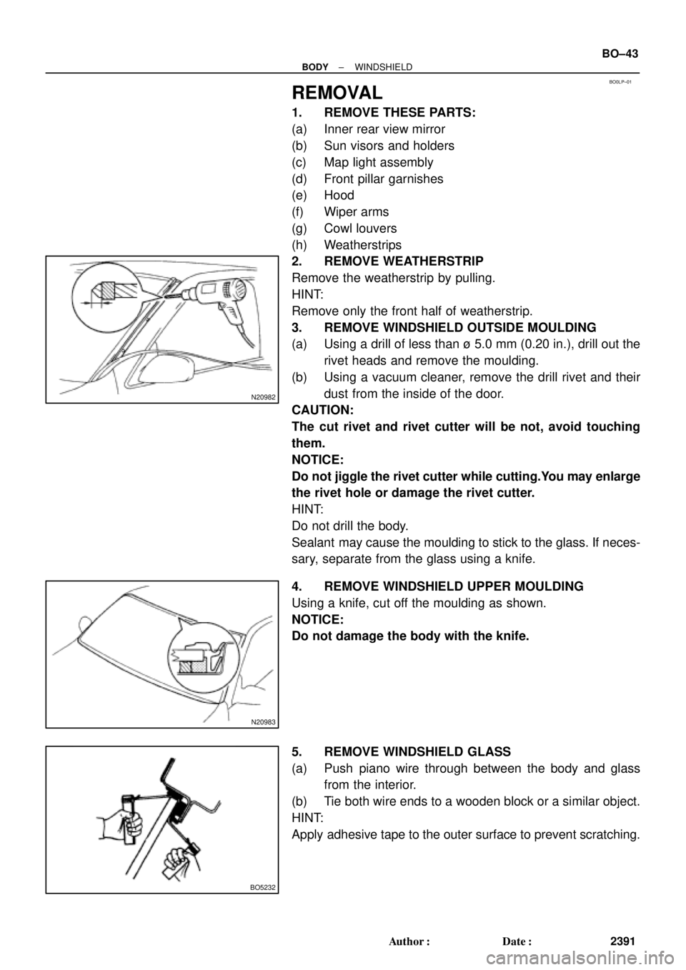
3. REMOVE WINDSHIELD OUTSIDE MOULDING
(a) Using a drill of less than ù 5.0 mm (0.20 in.), drill out the
rivet heads and remove the moulding.
(b) Using a vacuum cleaner, remove the drill rivet and their
dust from the inside of the door.
CAUTION:
The cut rivet and rivet cutter will be not, avoid touching
them.
NOTICE:
Do not jiggle the rivet cutter while cutting.You may enlarge
the rivet hole or damage the rivet cutter.
HINT:
Do not drill the body.
Sealant may cause the moulding to stick to the glass. If neces-
sary, separate from the glass using a knife.
4. REMOVE WINDSHIELD UPPER MOULDING
Using a knife, cut off the moulding as shown.
NOTICE:
Do not damage the body with the knife.
5. REMOVE WINDSHIELD GLASS
(a) Push piano wire through between the body and glass
from the interior.
(b) Tie both wire ends to a wooden block or a similar object.
HINT:
Apply adhesive tape to the outer surface to prevent scratching.
Page 919 of 4592
BO0MC±01
N20987
N21123
± BODYINSTRUMENT PANEL
BO±75
2423 Author�: Date�:
REMOVAL
1. REMOVE THESE PARTS:
HINT:
Tape a screwdriver tip before use.
(a) Front door inside scuff plates
(b) Cowl side trims
(c) Front pillar garnishes
(d) Front door opening covers
(e) Lower finish plate
2. REMOVE STEERING WHEEL
(See page SR±11)
3. REMOVE STEERING COLUMN COVERS
(a) Remove the steering tilt handle.
(b) Remove the 3 screws, then the upper and lower column
covers.
4. REMOVE COMBINATION SWITCH
5. REMOVE No.1 LOWER PANEL
(a) Remove the 2 screws and hood lock release lever.
(b) Press on the sides of the coin box while pulling the coin
box outward, and remove the coin box.
(c) Remove the screw, bolt and the No.1 lower panel.
6. REMOVE LOWER PANEL INSERT
(a) Remove the 2 screws holding the DLC3 to the LH lower
panel.
(b) Remove the 4 bolts, and the panel.
7. REMOVE No.2 LOWER COVER
Page 975 of 4592

H01880
SST SST
R13455
10 m (33 ft) or more BO±130
± BODYSEAT BELT PRETENSIONER
2478 Author�: Date�:
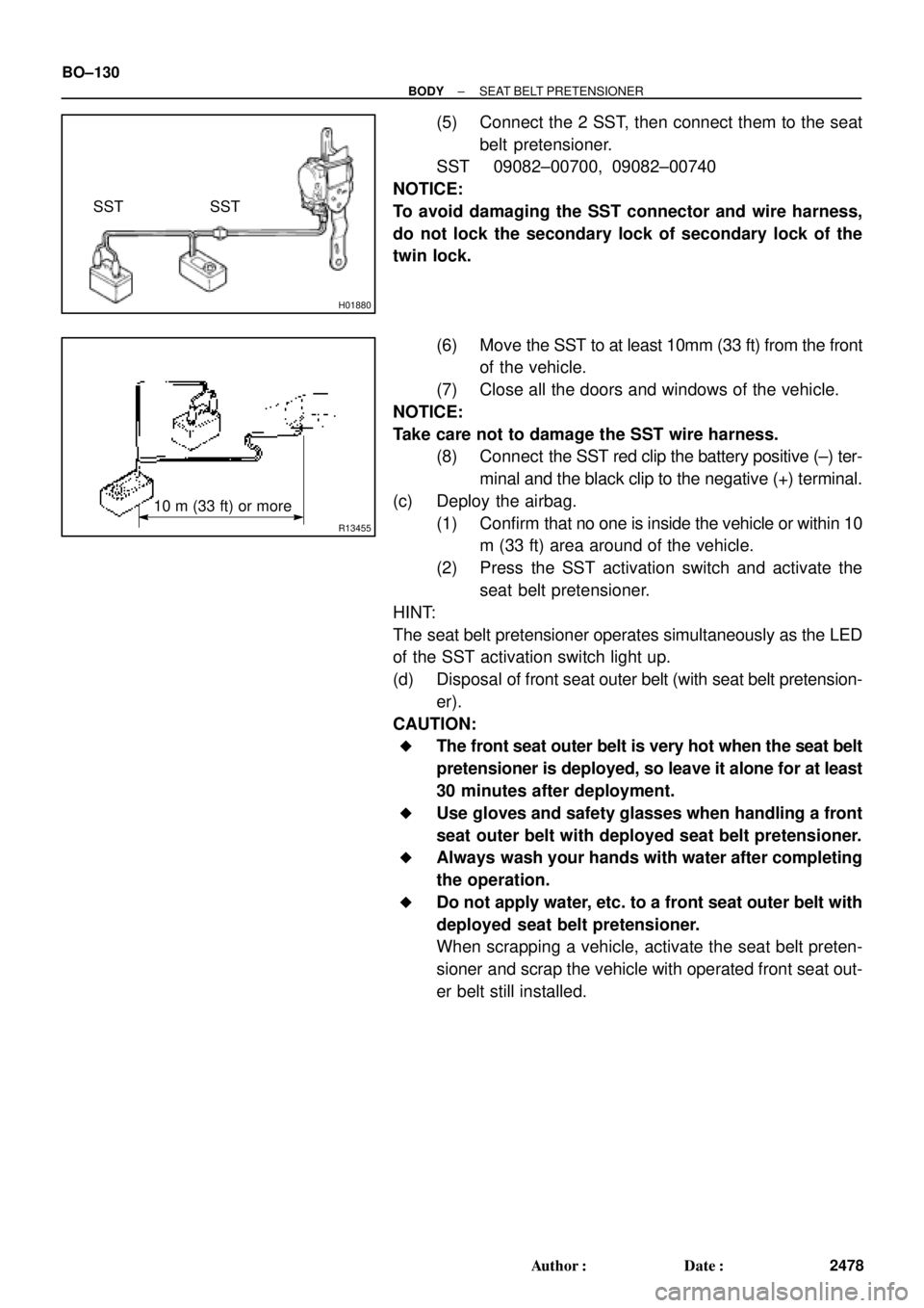
(5) Connect the 2 SST, then connect them to the seat
belt pretensioner.
SST 09082±00700, 09082±00740
NOTICE:
To avoid damaging the SST connector and wire harness,
do not lock the secondary lock of secondary lock of the
twin lock.
(6) Move the SST to at least 10mm (33 ft) from the front
of the vehicle.
(7) Close all the doors and windows of the vehicle.
NOTICE:
Take care not to damage the SST wire harness.
(8) Connect the SST red clip the battery positive (±) ter-
minal and the black clip to the negative (+) terminal.
(c) Deploy the airbag.
(1) Confirm that no one is inside the vehicle or within 10
m (33 ft) area around of the vehicle.
(2) Press the SST activation switch and activate the
seat belt pretensioner.
HINT:
The seat belt pretensioner operates simultaneously as the LED
of the SST activation switch light up.
(d) Disposal of front seat outer belt (with seat belt pretension-
er).
CAUTION:
�The front seat outer belt is very hot when the seat belt
pretensioner is deployed, so leave it alone for at least
30 minutes after deployment.
�Use gloves and safety glasses when handling a front
seat outer belt with deployed seat belt pretensioner.
�Always wash your hands with water after completing
the operation.
�Do not apply water, etc. to a front seat outer belt with
deployed seat belt pretensioner.
When scrapping a vehicle, activate the seat belt preten-
sioner and scrap the vehicle with operated front seat out-
er belt still installed.
Page 991 of 4592

BO2DO±02
H09250
Luggage Compartment
Door HingeLuggage Compartment DoorLuggage Compartment
Door Hinge
Door Lock Cylinder
Door Lock StrikerDoor Lock
Door Support
Inner Luggage Compartment
Trim Cover
Spare Wheel
Rear SeatbackSpare Wheel Cover
Spare Wheel
Carrier
Spare Wheel
Carrier Spacer
Luggage Compartment
Trim Front Cover
Rear Floor Finish
Side Plate
Rear Seat Outer BeltInner Lower Luggage
Compartment Trim Cover
Rear Seat Outer Belt Rear Floor Finish
Side Plate
Rear Seat CushionRoof Side
Inner Garnish
No. 1 Upper Back Panel Hole CoverPackage Tray Trim High±mounted
Stop Light
Roof Side
Inner Garnish
41 (420, 31)
41 (420, 31)
7.8 (80, 69 in.´lbf)
5.4 (55, 49 in.´lbf)
Luggage Compartment Door Cover
x11
N´m (kgf´cm, ft´lbf) : Specified TorqueReat Combination Light
22 (224, 16)
22 (224, 16)
5.4 (55, 49 in.´lbf)
18 (185, 13)
7.8 (80, 69 in.´lbf)
22 (224, 16)
Rear Floor
Finish Plate
± BODYLUGGAGE COMPARTMENT DOOR AND HINGE
BO±5
544 Author�: Date�:
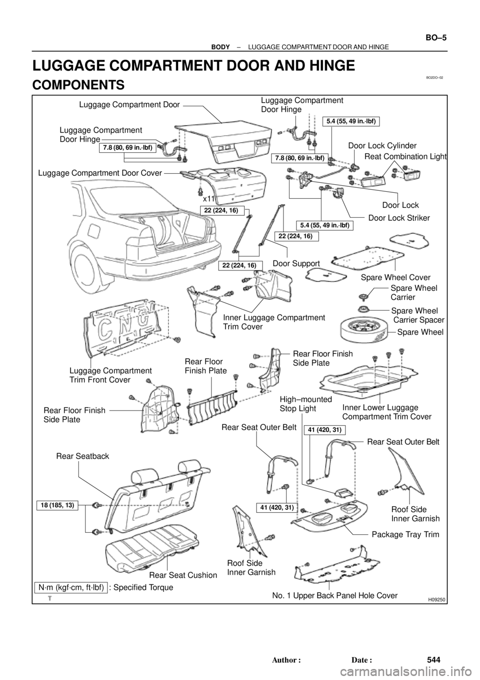
LUGGAGE COMPARTMENT DOOR AND HINGE
COMPONENTS
Page 994 of 4592
BO2DQ±01
BO±8
± BODYLUGGAGE COMPARTMENT DOOR AND HINGE
DISASSEMBLY
1. REMOVE DOOR LOCK
(a) Disconnect the control link.
(b) Remove the 2 bolts and door lock.
Torque: 5.4 N´m (55 kgf´cm, 49 in.´lbf)
2. REMOVE REAR COMBINATION LIGHTS
(a) Disconnect the connectors.
(b) Remove the 6 nuts and rear combination lights.
3. REMOVE DOOR LOCK CYLINDER
Remove the 2 bolts and door lock cylinder.
Torque: 5.4 N´m (55 kgf´cm, 49 in.´lbf)
Page 995 of 4592
BO2DR±01
H09256
N21779
± BODYLUGGAGE COMPARTMENT DOOR AND HINGE
BO±9
ADJUSTMENT
1. ADJUST LUGGAGE COMPARTMENT DOOR
(a) Remove the 11 clips and luggage compartment door cov-
er.
(b) Loosen the bolts to adjust the lggage compartment door
in forward/rearward and left/right directions.
(c) Tighten the loosened bolts again.
Torque: 7.8 N´m (80 kgf´cm, 69 in.´lbf)
(d) Increase or decrease the number of washers between the
hinge and door panel to adjust vertical direction.
2. ADJUST DOOR LOCK STRIKER
(a) Remove the rear floor finish side plates.
(b) Remove the rear floor finish plate.
(c) Loosen the 2 lock striker set bolts.
(d) Using a hammer and brass bar, tap the striker to adjust it.
(e) Tighten the loosened bolts again.
Torque: 5.4 N´m (55 kgf´cm, 49 in.´lbf)
Page 2012 of 4592

DI05L±03
Vehicle Brought to Workshop
Customer Problem Analysis
Circuit Inspection
Symptom Simulation
Identification of Problem
Confirmation TestEND
1
23
4
7
Repair5
6
DI±801
IN±21
DI±809
Problem Symptom Confirmation
Diagnostic Procedure
Transmitter Inspection
Transmitter Malfunction
Titles inside are titles of pages in
this manual, with the page number indicated
in the bottom position. See the indicated
pages for detailed explanations.
Some functions of wireless door lock
control system do not operate Whole wireless
door lock control
system does not
operate
DI±802
DI±802
DI±810
8
Problem Symptoms Table DI±800
± DIAGNOSTICSWIRELESS DOOR LOCK CONTROL SYSTEM
1035 Author�: Date�:
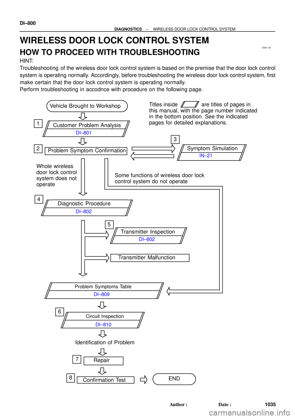
WIRELESS DOOR LOCK CONTROL SYSTEM
HOW TO PROCEED WITH TROUBLESHOOTING
HINT:
Troubleshooting of the wireless door lock control system is based on the premise that the door lock control
system is operating normally. Accordingly, before troubleshooting the wireless door lock control system, first
make certain that the door lock control system is operating normally.
Perform troubleshooting in accodnce with procedure on the following page.