Page 3411 of 4592
SF07K±04
S04505
S04498
S06086
Fuel Hose
Clamp
S05352
± SFI (1MZ±FE)INJECTOR
SF±23
1522 Author�: Date�:
REMOVAL
1. REMOVE AIR CLEANER HOSE
2. REMOVE AIR INTAKE CHAMBER ASSEMBLY
(See page EM±32)
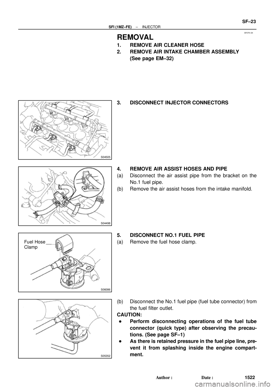
3. DISCONNECT INJECTOR CONNECTORS
4. REMOVE AIR ASSIST HOSES AND PIPE
(a) Disconnect the air assist pipe from the bracket on the
No.1 fuel pipe.
(b) Remove the air assist hoses from the intake manifold.
5. DISCONNECT NO.1 FUEL PIPE
(a) Remove the fuel hose clamp.
(b) Disconnect the No.1 fuel pipe (fuel tube connector) from
the fuel filter outlet.
CAUTION:
�Perform disconnecting operations of the fuel tube
connector (quick type) after observing the precau-
tions. (See page SF±1)
�As there is retained pressure in the fuel pipe line, pre-
vent it from splashing inside the engine compart-
ment.
Page 3413 of 4592
SF07L±04
B01919
Fuel Tube Connector
SST
(Hose)
SST
(Union)
SST
(Clamp)
InjectorFuel Filter
(On Vehicle) California A/T
Except California A/T
Fuel Tube Connector
SST
(Hose)
SST
(Union)
SST
(Clamp)
InjectorFuel Filter
(On Vehicle)
S05359
Fuel Tube Connector
S05357
SST
(Hose) Fuel Tube Connector
Fuel Filter
± SFI (1MZ±FE)INJECTOR
SF±25
1524 Author�: Date�:
INSPECTION
1. INSPECT INJECTOR INJECTION
CAUTION:
Keep injector clear of sparks during the test.
(a) Purchase the new No.1 fuel pipe and take out the fuel
tube connector from its pipe.
Part No. 23801±20041
(b) Connect SST (hose ) and fuel tube connector to the fuel
filter outlet.
SST 09268±41047
CAUTION:
Preform connecting operations of the fuel tube connector
(quick type) after observing the precautions.
(See page SF±1)
HINT:
Use the vehicle fuel filter.
Page 3415 of 4592

BatterySST
(Wire)
B00628
California A/TExcept
California A/T
± SFI (1MZ±FE)INJECTOR
SF±27
1526 Author�: Date�:
(k) Connect SST (wire)")
B01913
California A/T
Except California A/TBatterySST
(Wire)
BatterySST
(Wire)
B00628
California A/TExcept
California A/T
± SFI (1MZ±FE)INJECTOR
SF±27
1526 Author�: Date�:
(k) Connect SST (wire) to the injector and battery for 15 se-
conds, and measure the injection volume with a gra-
duated cylinder. Test each injector 2 or 3 times.
SST 09842±30070
Volume:
60 ± 73 cm
3 (3.4 ± 4.5 cu in.) per 15 sec.
Difference between each injector:
13 cm
3 (0.8 cu in.) or less
If the injection volume is not as specified, replace the injector.
2. INSPECT LEAKAGE
(a) In the condition above, disconnect the test probes of SST
(wire) from the battery and check the fuel leakage from
the injector.
SST 09842±30070
Fuel drop: 1 drop or less per 12 minutes
(b) Turn the ignition switch OFF.
(c) Disconnect the negative (±) terminal cable from the bat-
tery.
(d) Remove the SST and fuel tube connector.
SST 09268±41047, 09842±30070
CAUTION:
�Perform disconnecting operations of the fuel tube
connector (quick type) after observing the precau-
tions. (See page SF±1)
�As there is retained pressure in the fuel pipe line, pre-
vent it from splashing inside the engine compart-
ment.
(e) Disconnect the TOYOTA hand±held tester from the
DLC3.
Page 3417 of 4592
INJECTOR
SF±29
1528 Author�: Date�:
(g) Apply a light coat of spindle oil or gasoline on the place
where a intake manifold touc")
B01021
S04728
Rotate
Outward
B01020
S06525
Align
S05351
± SFI (1MZ±FE)INJECTOR
SF±29
1528 Author�: Date�:
(g) Apply a light coat of spindle oil or gasoline on the place
where a intake manifold touches an O±ring of the injector.
(h) Place the delivery pipes and fuel pipe together with the 6
injectors in position on the intake manifold.
(i) Temporarily install the 4 bolts holding the delivery pipes
to the intake manifold.
(j) Temporarily install the bolt holding the No.1 fuel pipe to
the intake manifold.
(k) Check that the injectors rotate smoothly.
HINT:
If injectors do not rotate smoothly, the probable cause is incor-
rect installation of O±rings. Replace the O±rings.
(l) Position the injector connector outward.
(m) Tighten the 4 bolts holding the delivery pipes to the intake
manifold.
Torque: 10 N´m (100 kgf´cm, 7 ft´lbf)
(n) Tighten the bolt holding the No.1 fuel pipe to the intake
manifold.
Torque: 19.5 N´m (200 kgf´cm, 14 ft´lbf)
2. CONNECT NO.1 FUEL PIPE
(a) Align the alignment marks (white paint) on the No.1 fuel
pipe.
(b) Connect the No.1 fuel pipe (fuel tube connector) to the
fuel filter.
CAUTION:
Perform connecting operations of the fuel tube connector
(quick type) after observing the precaution.
(See page SF±1)
Page 3784 of 4592

45 mph
(72 km/h)
25 mph
(40 km/h)
Id")
READINESS MONITOR DRIVE PATTERNS ± EG003-02 RevisedMarch 29, 2002
Page 14 of 23
DRIVE PATTERN NO. 5: EVAP Monitor
(Internal Pressure Monitor/Non±Intrusive Type)
45 mph
(72 km/h)
25 mph
(40 km/h)
Idling
IG SW off
Soak
(1b)5 min
(2a)15 min
(2b) Warm up
ECT.176�F
(1a)
Cold Soak Drive Pattern
Cold Soak Preconditions
The monitor will not run unless:
�MIL is OFF.
�Fuel level is between 1/2 to 3/4 full (for faster completion)
.
�Altitude is 7800 feet (2400 m) or less.
IMPORTANT:
A cold soak must be performed prior to conducting the drive pattern to complete the
Internal Pressure Readiness Monitor.
Cold Soak Procedure
1a. Start the engine and allow ECT (Coolant Temp) to reach 176�F (80�C) or greater.
(This can be done by letting the engine idle or by driving the vehicle.)
1b. Let the vehicle cold soak for 8 hours or until the difference between IAT (Intake
Air) and ECT (Coolant Temp) is less than 13�F (7�C).
�Example 1
�ECT (Coolant Temp) = 75�F (24�C).
�IAT (Intake Air) = 60�F (16�C).
�Difference between ECT (Coolant Temp) and IAT (Intake Air) is 15�F (8�C).
%The monitor will not run because the difference between ECT (Coolant
Temp) and IAT (Intake Air) is greater than 13�F (7�C).
�Example 2
�ECT (Coolant Temp) = 70�F (21�C).
�IAT (Intake Air) = 68�F (20�C).
�Difference between ECT (Coolant Temp) and IAT (Intake Air) is 2�F (1�C).
%The monitor will run because the difference between ECT (Coolant Temp)
and IAT (Intake Air) is less than 13�F (7�C).
Readiness
Monitor
Drive
Patterns:
EVAP
Monitors
Page 3786 of 4592

Idling
IG SW off
Warm up
(2a) Soak
(1a)15 ±")
READINESS MONITOR DRIVE PATTERNS ± EG003-02 RevisedMarch 29, 2002
Page 16 of 23
DRIVE PATTERN NO. 6: EVAP Monitor (Vacuum Pressure Monitor/Intrusive Type)
Idling
IG SW off
Warm up
(2a) Soak
(1a)15 ±50 min
(When the Readiness Monitor or
DTC is set, this test is complete.)
(2c)
10 sec
(2b)
3,000 rpm
Cold Soak Preconditions
The monitor will not run unless:
�MIL is OFF.
�Fuel level is between 1/2 to 3/4 full (for faster completion)
.
�Altitude is 7800 feet (2400 m) or less.
Cold Soak Procedure
1a. Let the vehicle cold soak for 8 hours or until the difference between IAT (Intake
Air) and ECT (Coolant Temp) is less than 13�F (7�C).
�Example 1
�ECT (Coolant Temp) = 75�F (24�C).
�IAT (Intake Air) = 60�F (16�C).
�Difference between ECT (Coolant Temp) and IAT (Intake Air) is 15�F (8�C).
%The monitor will not run because the difference between ECT (Coolant
Temp) and IAT (Intake Air) is greater than 13�F (7�C).
�Example 2
�ECT (Coolant Temp) = 70�F (21�C).
�IAT (Intake Air) = 68�F (20�C).
�Difference between ECT (Coolant Temp) and IAT (Intake Air) is 2�F (1�C).
%The monitor will run because the difference between ECT (Coolant Temp)
and IAT (Intake Air) is less than 13�F (7�C).
Readiness
Monitor
Drive
Patterns:
EVAP
Monitors
(Continued)
Page 3800 of 4592
 EVAP System Overview
There are a variety of EVAP systems in use with different monitoring strategi")
EVAP SYSTEM OPERATION INFORMATION ± EG005-01 April 27, 2001
Page 2 of 14
Early Type (Non±Intrusive) EVAP System Overview
There are a variety of EVAP systems in use with different monitoring strategies. It is
essential that the EVAP system be correctly identified before beginning diagnosis. The
Repair Manual is the best source for this information. The following information covers
the different systems.
The first system described is the Early Type (Non±Intrusive) EVAP System. Refer to the
Applicable Vehicles chart for applicability information.
Onboard Recovery Valve
(Fill Check Valve)Vapor
Pressure
SensorVapor
Pressure
Sensor
Three Way
VSVVacuum
Check
ValveTank Valve
AssemblyPressure
ValveCanister
To
Manifold
Vacuum
Purge
Valve
Filtered
Air
Air Drain Valve
Air Valve AssemblyAir Inlet ValveAir Inlet LineService
Port
Purge Operation
When the engine has reached
predetermined parameters (closed loop,
engine temp. above 125�F, etc.), stored
fuel vapors are purged from the canister
whenever the purge VSV is opened by
the ECM. At the appropriate time, the
ECM will turn on the purge VSV.
The ECM will change the duty ratio cycle
of the purge VSV thus controlling purge
flow volume. Purge flow volume is
determined by manifold pressure and the
duty ratio cycle of the purge VSV.
Atmospheric pressure is allowed into the
canister to ensure that purge flow is
constantly maintained whenever purge
vacuum is applied to the canister (see
Figure 1).
Early Type
System
Description
Figure 1. Purge OperationFresh Air Inlet
Purge VSV
Page 3801 of 4592

EVAP SYSTEM OPERATION INFORMATION ± EG005-01 April 27, 2001
Page 3 of 14
ORVR Operation
During refueling, low pressure above the
diaphragm in the onboard recovery valve
lifts allowing fuel vapors into the charcoal
canister. At the same time, the air drain
valve opens and the charcoal absorbs the
fuel vapors (see Figure 2).
Early Type (Non±Intrusive) EVAP System DTCs
EVAP Monitor Leak Operation P0440
The ECM tests for leaks by measuring
EVAP system pressure in the lines,
charcoal canister, and fuel tank. When
the EVAP pressure is higher or lower than
atmospheric pressure, the ECM
concludes that no leaks are present.
EVAP pressure is measured by the vapor
pressure sensor. If either the tank or
canister purge side is at atmospheric
pressure under specific conditions, the
ECM determines there is a leak.
If DTC P0440 is present, the leak is on
the fuel tank side of the EVAP system.
This also includes the lines between the
fuel tank and part of the canister. When
the Vapor Pressure sensor is measuring
tank pressure, the ECM is observing
changes in pressure and comparing tank
pressure to atmospheric pressure. No
difference in pressure indicates a leak.
The ECM may take 20 minutes or more to
complete testing the fuel tank side (see
Figure 3).
Canister Leak Detection P0446
When the ECM switches the vapor
pressure VSV to canister side, the ECM
measures canister pressure. A leak on
the canister side can set multiple DTCs
(see Figure 4).Early Type
System
Description
(Continued)
Figure 2. ORVR Operation
Figure 3. Fuel Tank Side of System
Figure 4. Canister Side of System

SST
(Union)
SST
(Clamp)
InjectorFuel Filter
(On Vehicle) California A/T
Except California A/T
Fuel Tube Connector
SST
(Hose)
SST
(Union)
SST
(Clamp)
Inj")