Page 2744 of 4592
ENGINE UNIT
EM±79
1365 Author�: Date�:
(f) Connect the 2 ground strap connectors to the LH fender
apron.
(g) Connect the DLC1 to the RH fender apron.
(h) Connect")
S05048
± ENGINE MECHANICAL (1MZ±FE)ENGINE UNIT
EM±79
1365 Author�: Date�:
(f) Connect the 2 ground strap connectors to the LH fender
apron.
(g) Connect the DLC1 to the RH fender apron.
(h) Connect the ground cable to the battery body bracket.
(i) Connect the engine wire protector clamp to the battery
body bracket.
(j) Connect the engine wire clamp to the bracket on the RH
fender apron.
(k) Connect the engine wire clamp to the bracket on the fuel
filter.
(l) Connect the brake booster vacuum hose to the air intake
chamber.
(m) Connect the engine coolant reservoir hose to the water
outlet.
(n) Connect the heater hose to the intake manifold.
(o) Connect the heater hose to the water inlet housing.
(p) Connect the fuel inlet hose to the fuel filter.
CAUTION:
Perform connecting operations of the fuel tube connector
(quick type) after observing the precautions.
(See page SF±6)
(q) Connect the purge hose to the pipe on the emission con-
trol valve set.
(r) Connect the 2 vacuum hoses to the vacuum tank for the
ACIS.
21. INSTALL FRONT EXHAUST PIPE
(a) Temporarily install 3 new gaskets and the front exhaust
pipe with the 2 bolts and 6 nuts.
(b) Tighten the 4 nuts holding the exhaust manifolds to the
front exhaust pipe.
Torque: 62 N´m (630 kgf´cm, 46 ft´lbf)
(c) Tighten the 2 bolts and 2 nuts holding the front exhaust
pipe to the center exhaust pipe.
Torque: 56 N´m (570 kgf´cm, 41 ft´lbf)
(d) Install the bracket with the 2 bolts.
Torque: 33 N´m (330 kgf´cm, 24 ft´lbf)
(e) Install the support stay with the 2 bolts.
Torque: 33 N´m (330 kgf´cm, 24 ft´lbf)
22. INSTALL RADIATOR (See page CO±24)
23. INSTALL CRUISE CONTROL ACTUATOR
24. INSTALL AIR CLEANER CAP ASSEMBLY AND AIR
CLEANER CASE
25. CONNECT ACCELERATOR CABLE
26. INSTALL ENGINE FENDER APRON SEALS
27. INSTALL BATTERY TRAY AND BATTERY
Page 2842 of 4592

± INTRODUCTIONTERMS
IN±39
39 Author�: Date�:
OHVOverhead Valve
OPTOption
O/SOversize
P & BVProportioning And Bypass Valve
PCSPower Control System
PCVPositive Crankcase Ventilation
PKBParking Brake
PPSProgressive Power Steering
PSPower Steering
PTOPower Take±Off
R & PRack And Pinion
R/BRelay Block
RBSRecirculating Ball Type Steering
R/FReinforcement
RFSRigid Front Suspension
RRSRigid Rear Suspension
RHRight±Hand
RHDRight±Hand Drive
RLYRelay
ROMRead Only Memory
RrRear
RRRear±Engine Rear±Wheel Drive
RWDRear±Wheel Drive
SDNSedan
SENSensor
SICSStarting Injection Control System
SOCState Of Charge
SOHCSingle Overhead Camshaft
SPECSpecification
SPISingle Point Injection
SRSSupplemental Restraint System
SSMSpecial Service Materials
SSTSpecial Service Tools
STDStandard
STJCold±Start Fuel Injection
SWSwitch
SYSSystem
T/ATransaxle
TACHTachometer
TBIThrottle Body Electronic Fuel Injection
TCTurbocharger
TCCSTOYOTA Computer±Controlled System
TCVTiming Control Valve
TDCTop Dead Center
TEMP.Temperature
TEMSTOYOTA Electronic Modulated Suspension
Page 2883 of 4592

± INTRODUCTIONTERMS
IN±37
37 Author�: Date�:
OHVOverhead Valve
OPTOption
O/SOversize
P & BVProportioning And Bypass Valve
PCSPower Control System
PCVPositive Crankcase Ventilation
PKBParking Brake
PPSProgressive Power Steering
PSPower Steering
PTOPower Take±Off
R & PRack And Pinion
R/BRelay Block
RBSRecirculating Ball Type Steering
R/FReinforcement
RFSRigid Front Suspension
RRSRigid Rear Suspension
RHRight±Hand
RHDRight±Hand Drive
RLYRelay
ROMRead Only Memory
RrRear
RRRear±Engine Rear±Wheel Drive
RWDRear±Wheel Drive
SDNSedan
SENSensor
SICSStarting Injection Control System
SOCState Of Charge
SOHCSingle Overhead Camshaft
SPECSpecification
SPISingle Point Injection
SRSSupplemental Restraint System
SSMSpecial Service Materials
SSTSpecial Service Tools
STDStandard
STJCold±Start Fuel Injection
SWSwitch
SYSSystem
T/ATransaxle
TACHTachometer
TBIThrottle Body Electronic Fuel Injection
TCTurbocharger
TCCSTOYOTA Computer±Controlled System
TCVTiming Control Valve
TDCTop Dead Center
TEMP.Temperature
TEMSTOYOTA Electronic Modulated Suspension
Page 3258 of 4592
SS0AH±03
SS±20
± SERVICE SPECIFICATIONSSFI (5S±FE)
183 Author�: Date�:
TORQUE SPECIFICATION
Part tightenedN´mkgf´cmft´lbf
Fuel line
Union bolt type
Flare nut type for use with SST
29
28
300
285
21
21
Fuel pump assembly x Fuel tank44035 in.´lbf
Fuel filter x Fuel pump bracket22017 in.´lbf
Fuel pressure regulator x Fuel pump bracket22017 in.´lbf
Delivery pipe x Cylinder head131309
Fuel tank band x Body3940029
Throttle body x Intake manifold1919514
Knock sensor 1 x Cylinder block4445032
A/F sensor x Exhaust manifold4445032
Oxygen sensor (bank 1 sensor 1) x Exhaust manifold4445032
Oxygen sensor (bank 1 sensor 2) x Front exhaust pipe4445032
Page 3260 of 4592
SS10A±01
SS±22
± SERVICE SPECIFICATIONSSFI (1MZ±FE)
185 Author�: Date�:
TORQUE SPECIFICATION
Part tightenedN´mkgf´cmft´lbf
Fuel line (Union bolt type)2930021
Fuel line (Flare nut type) using SST2828521
Fuel pump assembly x Fuel tank44035 in.´lbf
Fuel filter x Fuel pump bracket22017 in.´lbf
Fuel pressure regulator x Fuel pump bracket22017 in.´lbf
Delivery pipe x Intake manifold101007
No.1 fuel pipe x Intake manifold19.520014
Fuel tank band x Body3940029
Throttle body x Air intake chamber19.520014
Intake air control valve x Air intake chamber14.514510
ECT sensor x Water outlet2020014
Knock sensor x Cylinder block3940029
A/F sensor x Exhaust manifold4445032
Heated oxygen sensor (Bank 1, 2 sensor 1) x Exhaust manifold4445032
Heated oxygen sensor (Bank 1 sensor 2) x Exhaust pipe4445032
Page 3326 of 4592
SFI SYSTEM
1437 Author�:")
Z11336
California
Except CaliforniaGrommetInsulator O±Ring
InjectorO±Ring
O±Ring
Grommet
InjectorInsulator
S04583
Pull
S05040
Vinyl Bag
S05382
Retainer
SF±4
± SFI (5S±FE)SFI SYSTEM
1437 Author�: Date�:
(e) Install the injector to the delivery pipe and cylinder head,
as shown in the illustration.
Before installing the injector, must apply spindle oil or gas-
oline on the place where a delivery pipe or an intake man-
ifold touches an O±ring of the injector.
(f) Observe these precautions when disconnecting the fuel
tube connector (quick type):
(1) Check if there is any dirt like mud on the pipe and
around the connector before disconnecting them
and clean the dirt away.
(2) Be sure to disconnect with hands.
(3) When the connector and the pipe are stuck, pinch
the retainer between the hands, push and pull the
connector to free to disconnect and pull it out. Do
not use any tool at this time.
(4) Inspect if there is any dirt or the likes on the seal sur-
face of the disconnected pipe and clean it away.
(5) Prevent the disconnected pipe and connector from
damaging and mixing foreign objects by covering
them with a vinyl bag.
(g) Observe these precautions when connecting the fuel
tube connector (quick type):
(1) Do not reuse the retainer removed from the pipe.
(2) Must use hands without using tools when to remove
the retainer from the pipe.
(3) Check if there is any damage or foreign objects on
the connected part of the pipe.
Page 3331 of 4592
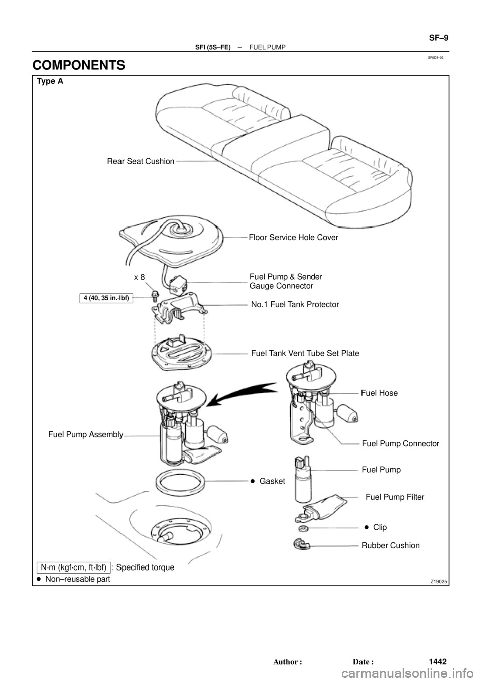
SF0D8±02
Z19025
Type A
Rear Seat Cushion
� Gasket
4 (40, 35 in.´lbf)
Floor Service Hole Cover
Fuel Pump & Sender
Gauge Connector
No.1 Fuel Tank Protector
Fuel Tank Vent Tube Set Plate
Fuel Hose
Fuel Pump Connector
Fuel Pump
Fuel Pump Filter
� Clip
Rubber Cushion Fuel Pump Assembly
N´m (kgf´cm, ft´lbf)
� Non±reusable part: Specified torquex 8
± SFI (5S±FE)FUEL PUMP
SF±9
1442 Author�: Date�:
COMPONENTS
Page 3332 of 4592
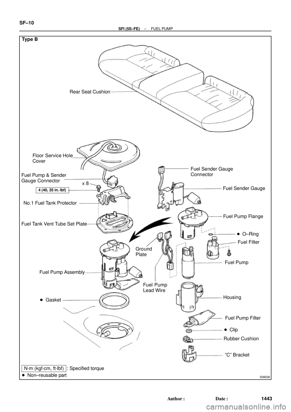
S06038
Type B
Rear Seat Cushion
� Gasket
4 (40, 35 in.´lbf)
Floor Service Hole
Cover
Fuel Pump & Sender
Gauge Connector
No.1 Fuel Tank Protector
Fuel Tank Vent Tube Set Plate
Fuel Filter Fuel Pump Flange
Fuel Pump
Fuel Pump Filter
� Clip
Rubber Cushion Fuel Pump Assembly
N´m (kgf´cm, ft´lbf)
� Non±reusable part� O±Ring
Housing
ºCº Bracket Fuel Sender Gauge
Fuel Pump
Lead Wire
: Specified torqueFuel Sender Gauge
Connector
Ground
Plate
x 8
SF±10
± SFI (5S±FE)FUEL PUMP
1443 Author�: Date�: