Page 2703 of 4592
P12780
Intake
7 85 6
3 41 2
9 10
P12888
7
85
6
3
41
2
9
10 Exhaust
P12917
Align Intake EM±38
± ENGINE MECHANICAL (1MZ±FE)CYLINDER HEAD
1324 Author�: Date�:
HINT:
When removing the camshaft, mark certain that the torsional
spring force of the sub±gear has been eliminated by the above
operation.
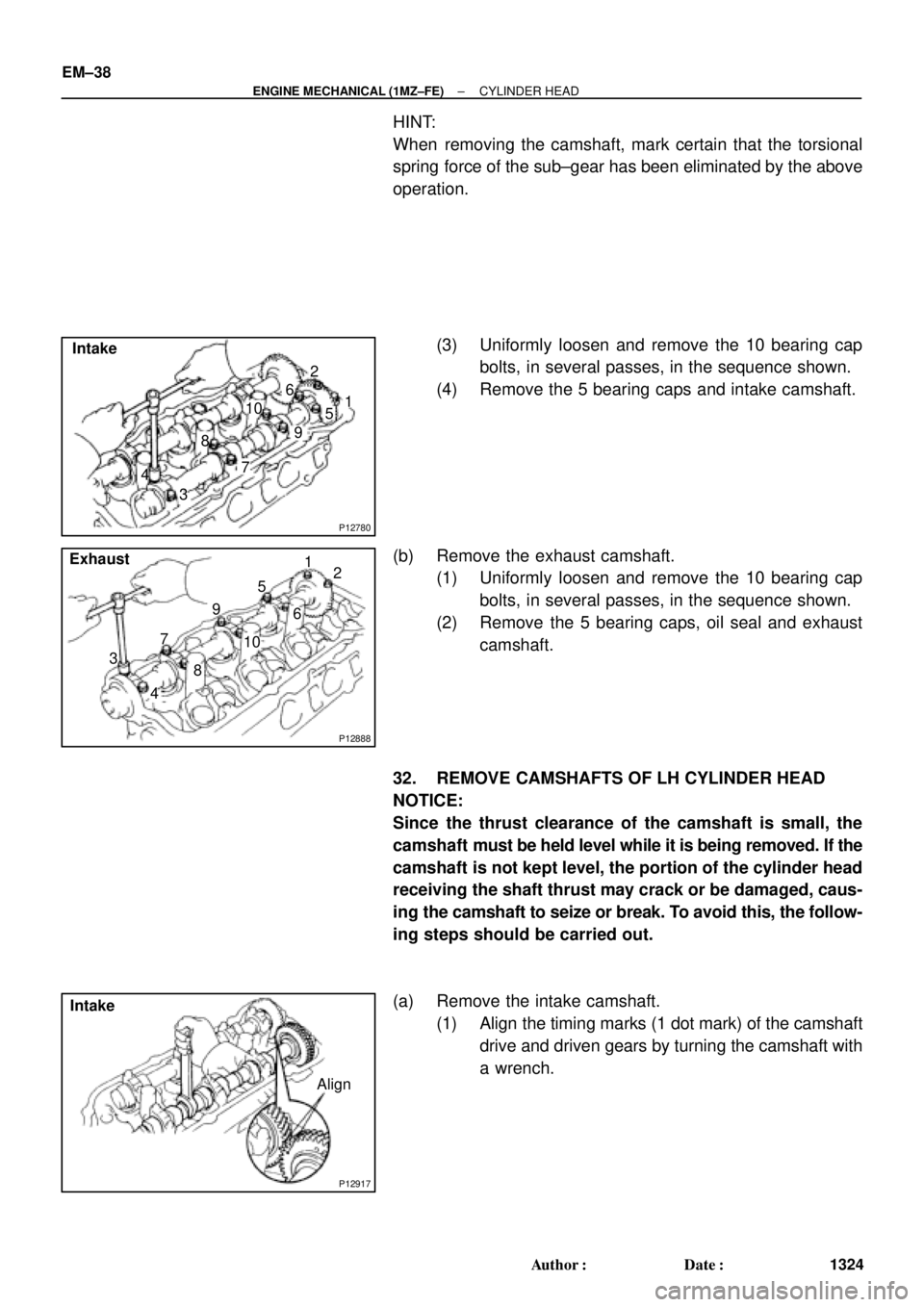
(3) Uniformly loosen and remove the 10 bearing cap
bolts, in several passes, in the sequence shown.
(4) Remove the 5 bearing caps and intake camshaft.
(b) Remove the exhaust camshaft.
(1) Uniformly loosen and remove the 10 bearing cap
bolts, in several passes, in the sequence shown.
(2) Remove the 5 bearing caps, oil seal and exhaust
camshaft.
32. REMOVE CAMSHAFTS OF LH CYLINDER HEAD
NOTICE:
Since the thrust clearance of the camshaft is small, the
camshaft must be held level while it is being removed. If the
camshaft is not kept level, the portion of the cylinder head
receiving the shaft thrust may crack or be damaged, caus-
ing the camshaft to seize or break. To avoid this, the follow-
ing steps should be carried out.
(a) Remove the intake camshaft.
(1) Align the timing marks (1 dot mark) of the camshaft
drive and driven gears by turning the camshaft with
a wrench.
Page 2724 of 4592
P12974
SST
Main Gear
Sub±Gear
P12963
90°Exhaust
P12804
Exhaust
Front
A02008
Exhaust
Seal
Packing
± ENGINE MECHANICAL (1MZ±FE)CYLINDER HEAD
EM±59
1345 Author�: Date�:
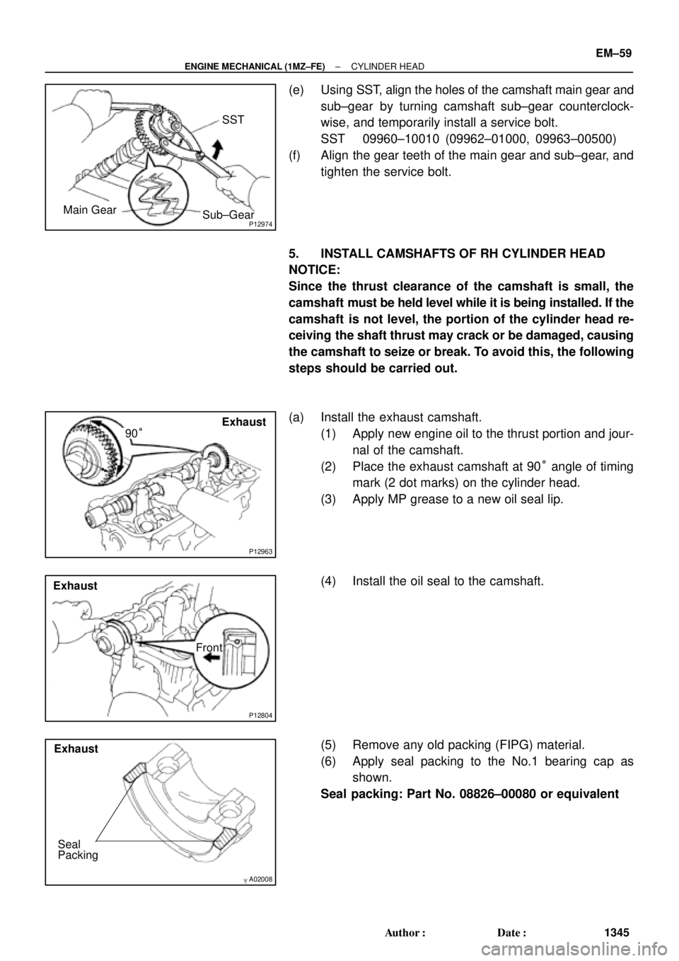
(e) Using SST, align the holes of the camshaft main gear and
sub±gear by turning camshaft sub±gear counterclock-
wise, and temporarily install a service bolt.
SST 09960±10010 (09962±01000, 09963±00500)
(f) Align the gear teeth of the main gear and sub±gear, and
tighten the service bolt.
5. INSTALL CAMSHAFTS OF RH CYLINDER HEAD
NOTICE:
Since the thrust clearance of the camshaft is small, the
camshaft must be held level while it is being installed. If the
camshaft is not level, the portion of the cylinder head re-
ceiving the shaft thrust may crack or be damaged, causing
the camshaft to seize or break. To avoid this, the following
steps should be carried out.
(a) Install the exhaust camshaft.
(1) Apply new engine oil to the thrust portion and jour-
nal of the camshaft.
(2) Place the exhaust camshaft at 90° angle of timing
mark (2 dot marks) on the cylinder head.
(3) Apply MP grease to a new oil seal lip.
(4) Install the oil seal to the camshaft.
(5) Remove any old packing (FIPG) material.
(6) Apply seal packing to the No.1 bearing cap as
shown.
Seal packing: Part No. 08826±00080 or equivalent
Page 2726 of 4592
P12870Service Bolt
Intake
P12884
Exhaust
90°
P12805
Exhaust
Front
A02008
Exhaust
Seal
Packing
± ENGINE MECHANICAL (1MZ±FE)CYLINDER HEAD
EM±61
1347 Author�: Date�:
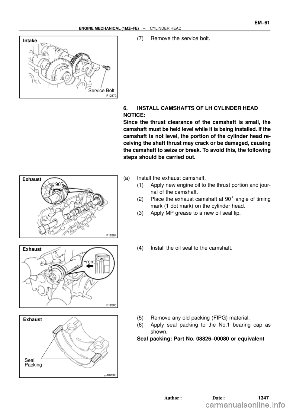
(7) Remove the service bolt.
6. INSTALL CAMSHAFTS OF LH CYLINDER HEAD
NOTICE:
Since the thrust clearance of the camshaft is small, the
camshaft must be held level while it is being installed. If the
camshaft is not level, the portion of the cylinder head re-
ceiving the shaft thrust may crack or be damaged, causing
the camshaft to seize or break. To avoid this, the following
steps should be carried out.
(a) Install the exhaust camshaft.
(1) Apply new engine oil to the thrust portion and jour-
nal of the camshaft.
(2) Place the exhaust camshaft at 90° angle of timing
mark (1 dot mark) on the cylinder head.
(3) Apply MP grease to a new oil seal lip.
(4) Install the oil seal to the camshaft.
(5) Remove any old packing (FIPG) material.
(6) Apply seal packing to the No.1 bearing cap as
shown.
Seal packing: Part No. 08826±00080 or equivalent
Page 2745 of 4592
EM±80
± ENGINE MECHANICAL (1MZ±FE)ENGINE UNIT
1366 Author�: Date�:
28. INSTALL HOOD
29. FILL ENGINE WITH OIL
30. FILL WITH ENGINE COOLANT
31. START ENGINE AND CHECK FOR LEAKS
32. PERFORM ROAD TEST
Check for abnormal noise, shock, slippage, correct shift points
and smooth operation.
33. RECHECK ENGINE COOLANT AND OIL LEVELS
Page 2769 of 4592
P12495
A05264
A05265
A05266
Less than 6 mm
A05267
EM±104
± ENGINE MECHANICAL (1MZ±FE)CYLINDER BLOCK
1390 Author�: Date�:
6. PLACE CRANKSHAFT ON CYLINDER BLOCK
7. PLACE MAIN BEARING CAPS AND LOWER THRUST
WASHERS ON CYLINDER BLOCK
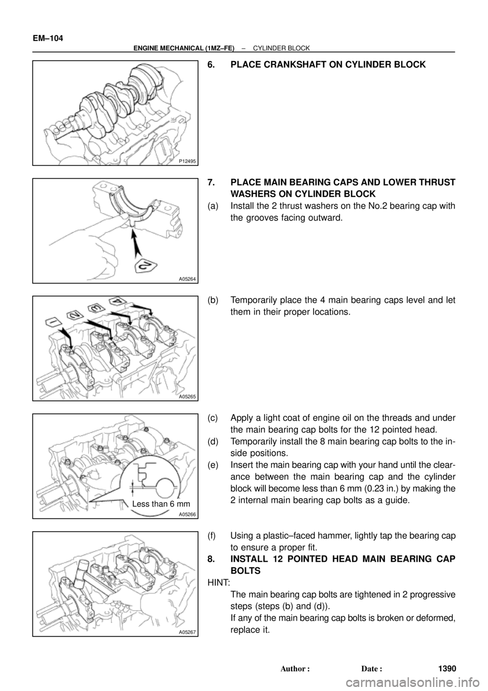
(a) Install the 2 thrust washers on the No.2 bearing cap with
the grooves facing outward.
(b) Temporarily place the 4 main bearing caps level and let
them in their proper locations.
(c) Apply a light coat of engine oil on the threads and under
the main bearing cap bolts for the 12 pointed head.
(d) Temporarily install the 8 main bearing cap bolts to the in-
side positions.
(e) Insert the main bearing cap with your hand until the clear-
ance between the main bearing cap and the cylinder
block will become less than 6 mm (0.23 in.) by making the
2 internal main bearing cap bolts as a guide.
(f) Using a plastic±faced hammer, lightly tap the bearing cap
to ensure a proper fit.
8. INSTALL 12 POINTED HEAD MAIN BEARING CAP
BOLTS
HINT:
�The main bearing cap bolts are tightened in 2 progressive
steps (steps (b) and (d)).
�If any of the main bearing cap bolts is broken or deformed,
replace it.
Page 2888 of 4592
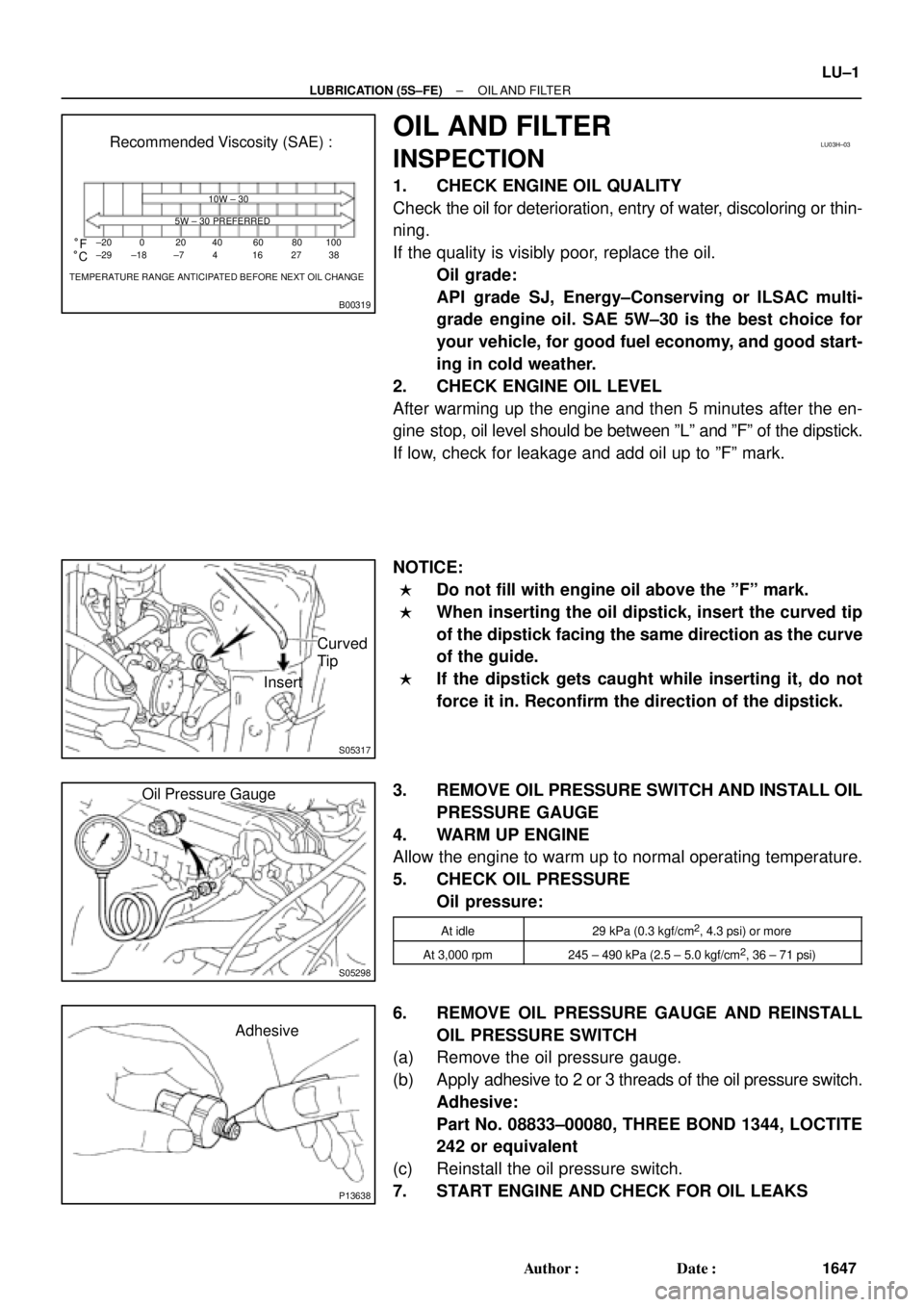
B00319
Recommended Viscosity (SAE) :
TEMPERATURE RANGE ANTICIPATED BEFORE NEXT OIL CHANGE 10W ± 30
5W ± 30 PREFERRED
±20
°C °F020406080
±29 ±18 ±7 4 16 27100
38
LU03H±03
S05317
Curved
Tip
Insert
S05298
Oil Pressure Gauge
P13638
Adhesive
± LUBRICATION (5S±FE)OIL AND FILTER
LU±1
1647 Author�: Date�:
OIL AND FILTER
INSPECTION
1. CHECK ENGINE OIL QUALITY
Check the oil for deterioration, entry of water, discoloring or thin-
ning.
If the quality is visibly poor, replace the oil.
Oil grade:
API grade SJ, Energy±Conserving or ILSAC multi-
grade engine oil. SAE 5W±30 is the best choice for
your vehicle, for good fuel economy, and good start-
ing in cold weather.
2. CHECK ENGINE OIL LEVEL
After warming up the engine and then 5 minutes after the en-
gine stop, oil level should be between ºLº and ºFº of the dipstick.
If low, check for leakage and add oil up to ºFº mark.
NOTICE:
�Do not fill with engine oil above the ºFº mark.
�When inserting the oil dipstick, insert the curved tip
of the dipstick facing the same direction as the curve
of the guide.
�If the dipstick gets caught while inserting it, do not
force it in. Reconfirm the direction of the dipstick.
3. REMOVE OIL PRESSURE SWITCH AND INSTALL OIL
PRESSURE GAUGE
4. WARM UP ENGINE
Allow the engine to warm up to normal operating temperature.
5. CHECK OIL PRESSURE
Oil pressure:
At idle29 kPa (0.3 kgf/cm2, 4.3 psi) or more
At 3,000 rpm245 ± 490 kPa (2.5 ± 5.0 kgf/cm2, 36 ± 71 psi)
6. REMOVE OIL PRESSURE GAUGE AND REINSTALL
OIL PRESSURE SWITCH
(a) Remove the oil pressure gauge.
(b) Apply adhesive to 2 or 3 threads of the oil pressure switch.
Adhesive:
Part No. 08833±00080, THREE BOND 1344, LOCTITE
242 or equivalent
(c) Reinstall the oil pressure switch.
7. START ENGINE AND CHECK FOR OIL LEAKS
Page 2890 of 4592
S05320
SST
3/4
Turn
± LUBRICATION (5S±FE)OIL AND FILTER
LU±3
1649 Author�: Date�:
(e) Using SST, give it an additional 3/4 turn to seat the filter.
SST 09228±06501
3. FILL WITH ENGINE OIL
(a) Clean and install the oil drain plug with a new gasket.
Torque: 37 N´m (375 kgf´cm, 27 ft´lbf)
(b) Fill with new engine oil.
Capacity:
Drain and refill w/ Oil filter change
w/o Oil filter change3.6 liters (3.8 US qts, 3.2 lmp. qts)
3.4 liters (3.6 US qts, 3.0 lmp. qts)
Dry fill w/ Oil cooler
w/o Oil cooler4.3 liters (4.5 US qts, 3.8 lmp. qts)
4.2 liters (4.4 US qts, 3.7 lmp. qts)
(c) Reinstall the oil filler cap.
4. START ENGINE AND CHECK FOR OIL LEAKS
5. RECHECK ENGINE OIL LEVEL
Page 2901 of 4592
LU±14
± LUBRICATION (5S±FE)OIL PUMP
1660 Author�: Date�: �
Immediately remove nozzle from the tube and rein-
stall the cap.
(c) Install the oil pan with the 17 bolts and 2 nuts. Uniformly
tighten the bolts and nuts in several passes.
(d) Install the dipstick.
8. INSTALL NO.2 REAR END PLATE, OIL PAN INSULA-
TOR AND EXHAUST PIPE BRACKET
(See page EM±75)
9. INSTALL LH STIFFENER PLATE AND NO.2 EXHAUST
MANIFOLD STAY (See page EM±23)
10. INSTALL FRONT EXHAUST PIPE
(See page EM±75)
11. FILL WITH ENGINE OIL
12. START ENGINE AND CHECK FOR OIL LEAKS
13. RECHECK ENGINE OIL LEVEL