Page 128 of 4592
AX03Q±02
AT3785
AT0103
D01019
Q05728
Connector
± AUTOMATIC TRANSAXLE (A541E)VALVE BODY ASSEMBLY
AX±7
1927 Author�: Date�:
VALVE BODY ASSEMBLY
ON±VEHICLE REPAIR
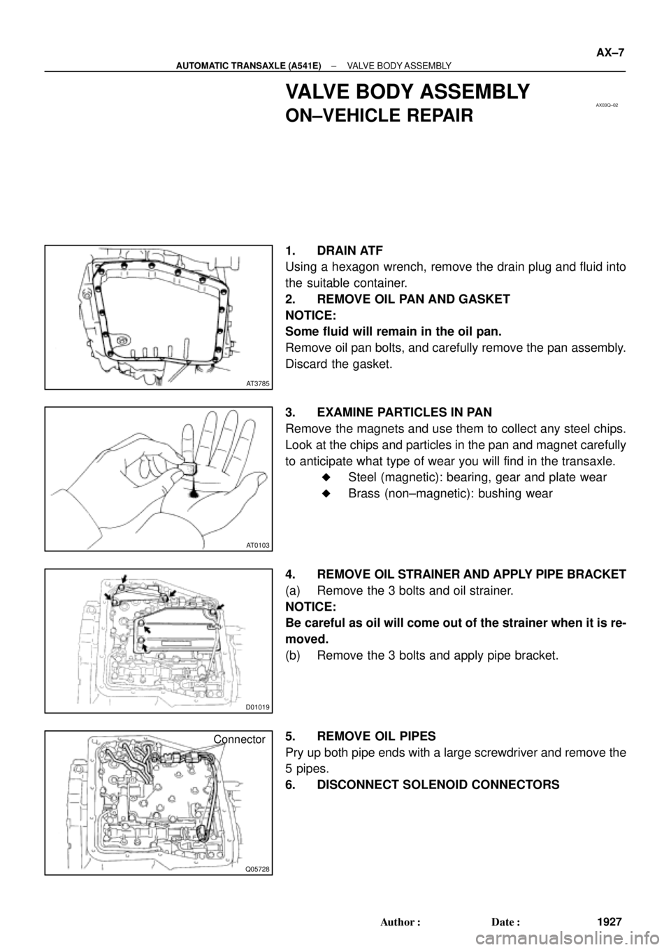
1. DRAIN ATF
Using a hexagon wrench, remove the drain plug and fluid into
the suitable container.
2. REMOVE OIL PAN AND GASKET
NOTICE:
Some fluid will remain in the oil pan.
Remove oil pan bolts, and carefully remove the pan assembly.
Discard the gasket.
3. EXAMINE PARTICLES IN PAN
Remove the magnets and use them to collect any steel chips.
Look at the chips and particles in the pan and magnet carefully
to anticipate what type of wear you will find in the transaxle.
�Steel (magnetic): bearing, gear and plate wear
�Brass (non±magnetic): bushing wear
4. REMOVE OIL STRAINER AND APPLY PIPE BRACKET
(a) Remove the 3 bolts and oil strainer.
NOTICE:
Be careful as oil will come out of the strainer when it is re-
moved.
(b) Remove the 3 bolts and apply pipe bracket.
5. REMOVE OIL PIPES
Pry up both pipe ends with a large screwdriver and remove the
5 pipes.
6. DISCONNECT SOLENOID CONNECTORS
Page 133 of 4592
Z19256
BA
B A
AT3741
AT3785
AX±12
± AUTOMATIC TRANSAXLE (A541E)VALVE BODY ASSEMBLY
1932 Author�: Date�:
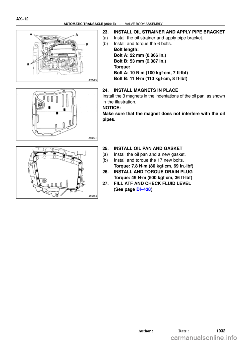
23. INSTALL OIL STRAINER AND APPLY PIPE BRACKET
(a) Install the oil strainer and apply pipe bracket.
(b) Install and torque the 6 bolts.
Bolt length:
Bolt A: 22 mm (0.866 in.)
Bolt B: 53 mm (2.087 in.)
Torque:
Bolt A: 10 N´m (100 kgf´cm, 7 ft´lbf)
Bolt B: 11 N´m (110 kgf´cm, 8 ft´lbf)
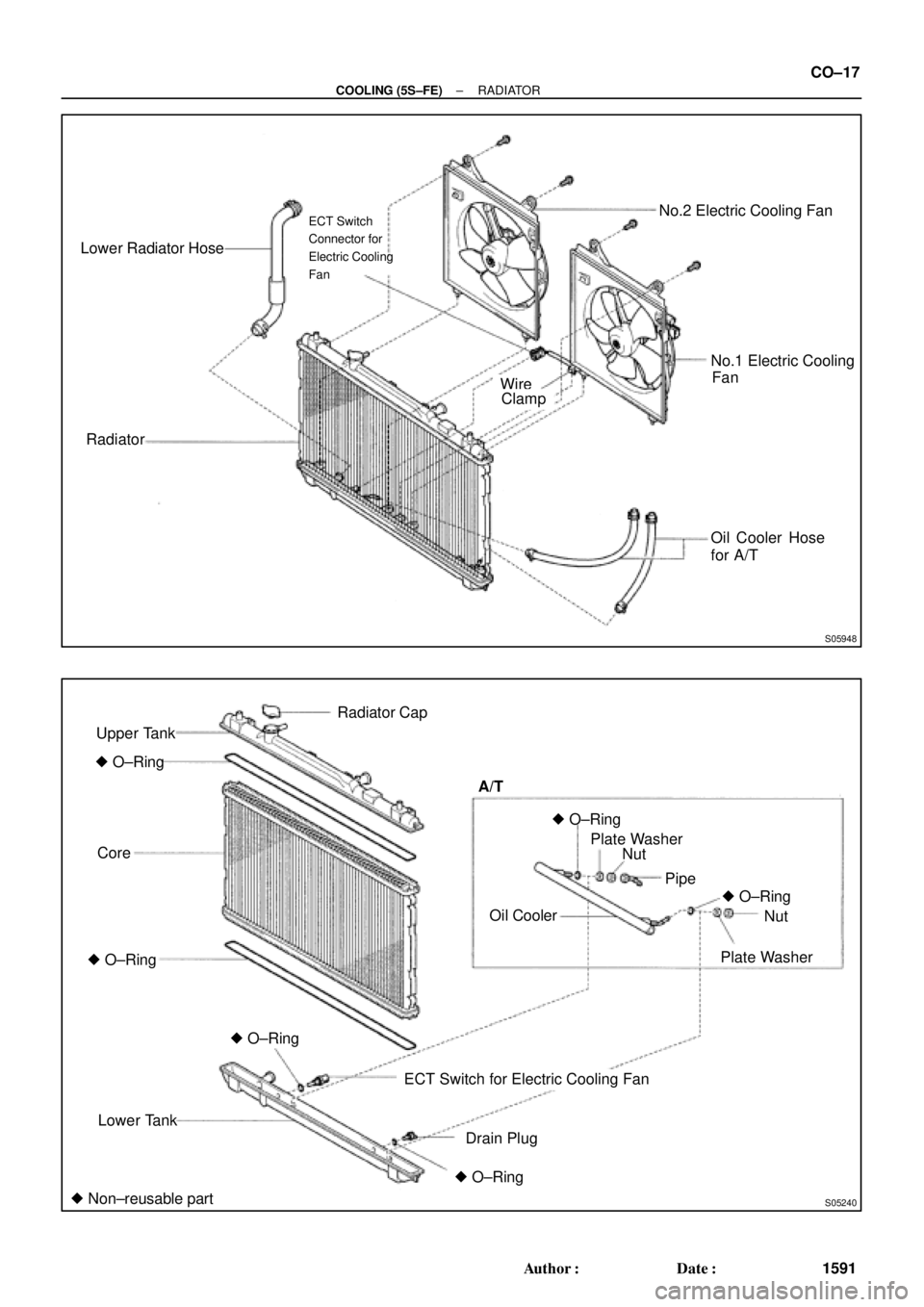
24. INSTALL MAGNETS IN PLACE
Install the 3 magnets in the indentations of the oil pan, as shown
in the illustration.
NOTICE:
Make sure that the magnet does not interfere with the oil
pipes.
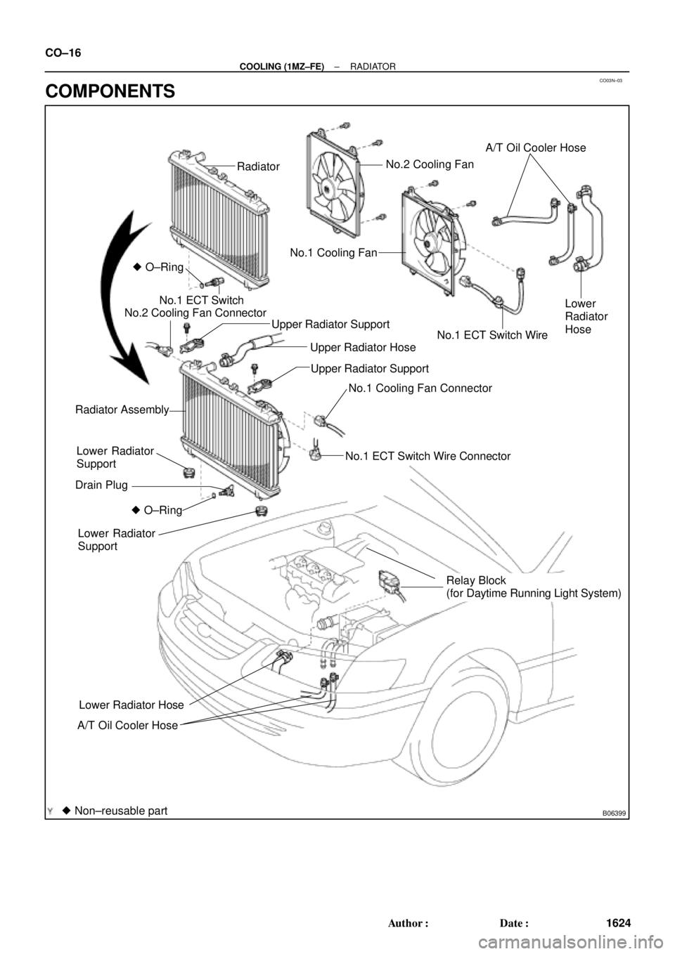
25. INSTALL OIL PAN AND GASKET
(a) Install the oil pan and a new gasket.
(b) Install and torque the 17 new bolts.
Torque: 7.8 N´m (80 kgf´cm, 69 in.´lbf)
26. INSTALL AND TORQUE DRAIN PLUG
Torque: 49 N´m (500 kgf´cm, 36 ft´lbf)
27. FILL ATF AND CHECK FLUID LEVEL
(See page DI±438)
Page 1142 of 4592
CO067±03
Z18990
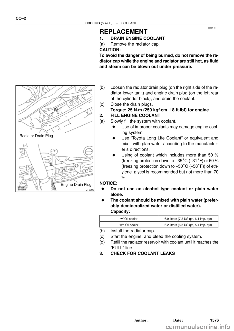
Radiator Drain Plug
Engine Drain Plug CO±2
± COOLING (5S±FE)COOLANT
1576 Author�: Date�:
REPLACEMENT
1. DRAIN ENGINE COOLANT
(a) Remove the radiator cap.
CAUTION:
To avoid the danger of being burned, do not remove the ra-
diator cap while the engine and radiator are still hot, as fluid
and steam can be blown out under pressure.
(b) Loosen the radiator drain plug (on the right side of the ra-
diator lower tank) and engine drain plug (on the left rear
of the cylinder block), and drain the coolant.
(c) Close the drain plugs.
Torque: 25 N´m (250 kgf´cm, 18 ft´lbf) for engine
2. FILL ENGINE COOLANT
(a) Slowly fill the system with coolant.
�Use of improper coolants may damage engine cool-
ing system.
�Use ºToyota Long Life Coolantº or equivalent and
mix it with plan water according to the manufactur-
er's directions.
�Using of coolant which includes more than 50 %
(freezing protection down to ±35°C (±31°F) or 60 %
(freezing protection down to ±50°C (±58°F)) of eth-
ylene±glycol is recommended but not more than 70
%.
NOTICE:
�Do not use an alcohol type coolant or plain water
alone.
�The coolant should be mixed with plain water (prefer-
ably demineralized water or distilled water).
Capacity:
w/ Oil cooler6.9 litters (7.3 US qts, 6.1 lmp. qts)
w/o Oil cooler6.2 litters (6.5 US qts, 5.4 lmp. qts)
(b) Install the radiator cap.
(c) Start the engine, and bleed the cooling system.
(d) Refill the radiator reservoir with coolant until it reaches the
ºFULLº line.
3. CHECK FOR COOLANT LEAKS
Page 1157 of 4592
S05948
Lower Radiator Hose
RadiatorNo.2 Electric Cooling Fan
No.1 Electric Cooling
Oil Cooler Hose
for A/T
ECT Switch
Connector for
Electric Cooling
Fan
FanWireClamp
S05240
Upper Tank
� O±Ring
Core
Lower Tank
ECT Switch for Electric Cooling Fan
Drain PlugOil Cooler A/T
Pipe
Plate WasherNut
� O±Ring� O±Ring
� O±Ring Radiator Cap
Nut Plate Washer
� Non±reusable part� O±Ring
� O±Ring
± COOLING (5S±FE)RADIATOR
CO±17
1591 Author�: Date�:
Page 1159 of 4592
CO06K±03
CO1205
Dimension ºBº
Overhaul HandleStopper Bolt SSTPart ºAº
Claw
S04699
Stopper
BoltSSTTank
Lock
Plate
S04703
Ta p
S04705
± COOLING (5S±FE)RADIATOR
CO±19
1593 Author�: Date�:
DISASSEMBLY
1. REMOVE ECT SWITCH
(a) Remove the ECT switch.
(b) Remove the O±ring.
2. REMOVE DRAIN PLUG
(a) Remove the drain plug.
(b) Remove the O±ring.
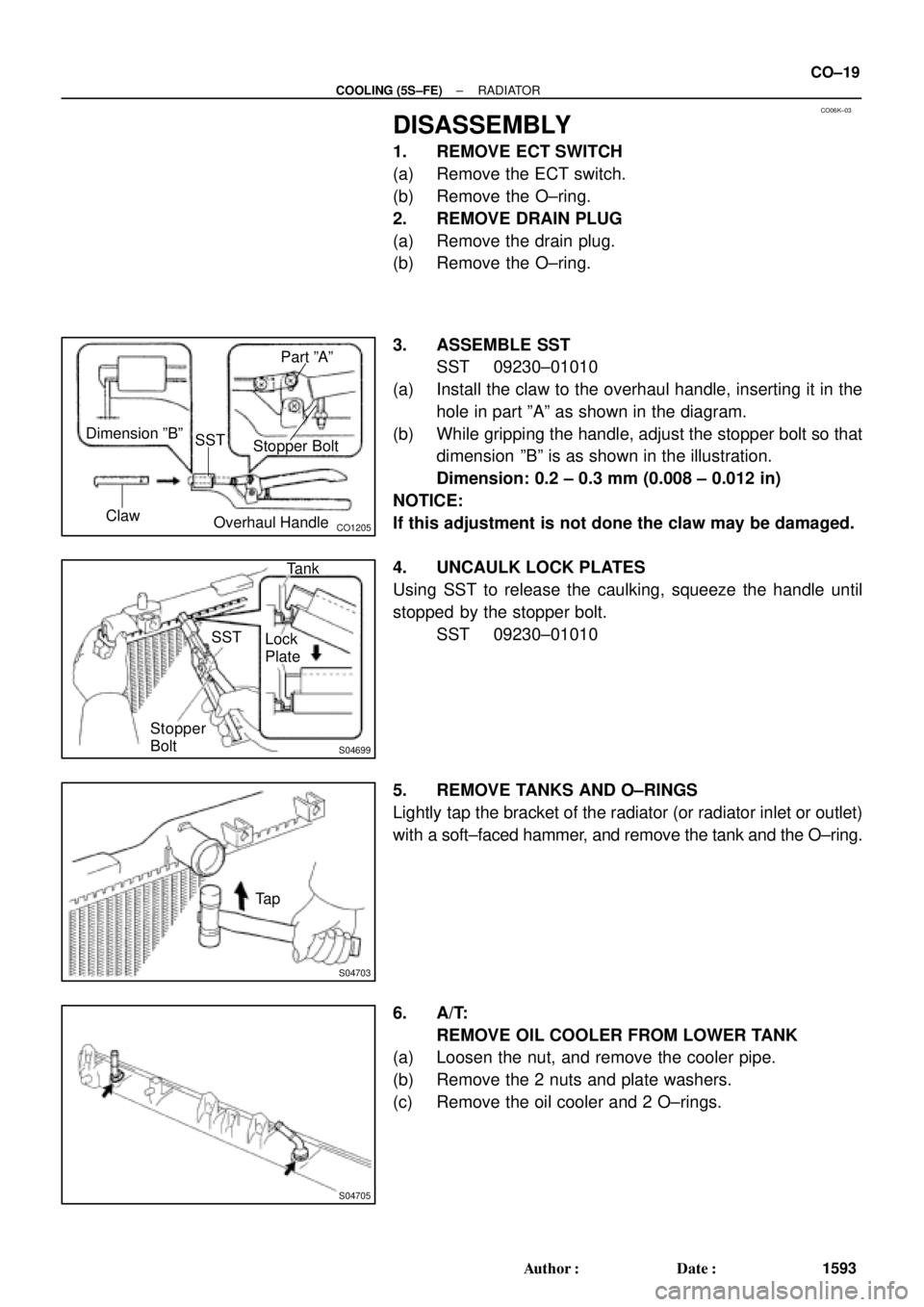
3. ASSEMBLE SST
SST 09230±01010
(a) Install the claw to the overhaul handle, inserting it in the
hole in part ºAº as shown in the diagram.
(b) While gripping the handle, adjust the stopper bolt so that
dimension ºBº is as shown in the illustration.
Dimension: 0.2 ± 0.3 mm (0.008 ± 0.012 in)
NOTICE:
If this adjustment is not done the claw may be damaged.
4. UNCAULK LOCK PLATES
Using SST to release the caulking, squeeze the handle until
stopped by the stopper bolt.
SST 09230±01010
5. REMOVE TANKS AND O±RINGS
Lightly tap the bracket of the radiator (or radiator inlet or outlet)
with a soft±faced hammer, and remove the tank and the O±ring.
6. A/T:
REMOVE OIL COOLER FROM LOWER TANK
(a) Loosen the nut, and remove the cooler pipe.
(b) Remove the 2 nuts and plate washers.
(c) Remove the oil cooler and 2 O±rings.
Page 1190 of 4592
CO03N±03
B06399
Radiator
No.1 ECT Switch
No.2 Cooling Fan Connector
Upper Radiator Support Upper Radiator Hose
No.1 Cooling Fan Connector
No.1 ECT Switch Wire Connector Radiator Assembly
Lower Radiator
Support� O±Ring
A/T Oil Cooler Hose
Relay Block
(for Daytime Running Light System) No.1 ECT Switch Wire No.1 Cooling FanNo.2 Cooling Fan
Upper Radiator Support
Lower Radiator
Support
� Non±reusable part� O±Ring Drain PlugLower
Radiator
Hose A/T Oil Cooler Hose
Lower Radiator Hose CO±16
± COOLING (1MZ±FE)RADIATOR
1624 Author�: Date�:
COMPONENTS
Page 1607 of 4592
Q00061
AT8562
AT3417
OK if hot
Add if hot
AT4252
0 ~ 1 mm (0 ~ 0.04 in.)
± DIAGNOSTICSAUTOMATIC TRANSAXLE (A140E)
DI±395
630 Author�: Date�:
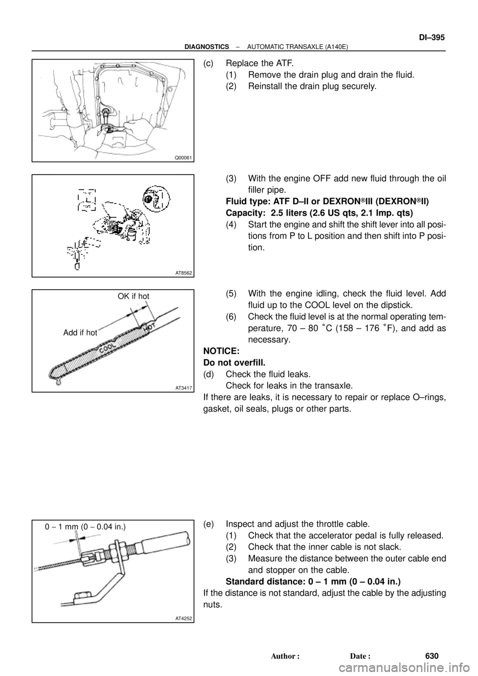
(c) Replace the ATF.
(1) Remove the drain plug and drain the fluid.
(2) Reinstall the drain plug securely.
(3) With the engine OFF add new fluid through the oil
filler pipe.
Fluid type: ATF D±II or DEXRON®III (DEXRON®II)
Capacity: 2.5 liters (2.6 US qts, 2.1 Imp. qts)
(4) Start the engine and shift the shift lever into all posi-
tions from P to L position and then shift into P posi-
tion.
(5) With the engine idling, check the fluid level. Add
fluid up to the COOL level on the dipstick.
(6) Check the fluid level is at the normal operating tem-
perature, 70 ± 80 °C (158 ± 176 °F), and add as
necessary.
NOTICE:
Do not overfill.
(d) Check the fluid leaks.
Check for leaks in the transaxle.
If there are leaks, it is necessary to repair or replace O±rings,
gasket, oil seals, plugs or other parts.
(e) Inspect and adjust the throttle cable.
(1) Check that the accelerator pedal is fully released.
(2) Check that the inner cable is not slack.
(3) Measure the distance between the outer cable end
and stopper on the cable.
Standard distance: 0 ± 1 mm (0 ± 0.04 in.)
If the distance is not standard, adjust the cable by the adjusting
nuts.
Page 1656 of 4592
AT4657
AT8562
AT3417
OK if hot
Add if hot
AT4252
0 ~ 1 mm (0 ~ 0.04 in.) DI±444
± DIAGNOSTICSAUTOMATIC TRANSAXLE (A541E)
679 Author�: Date�:
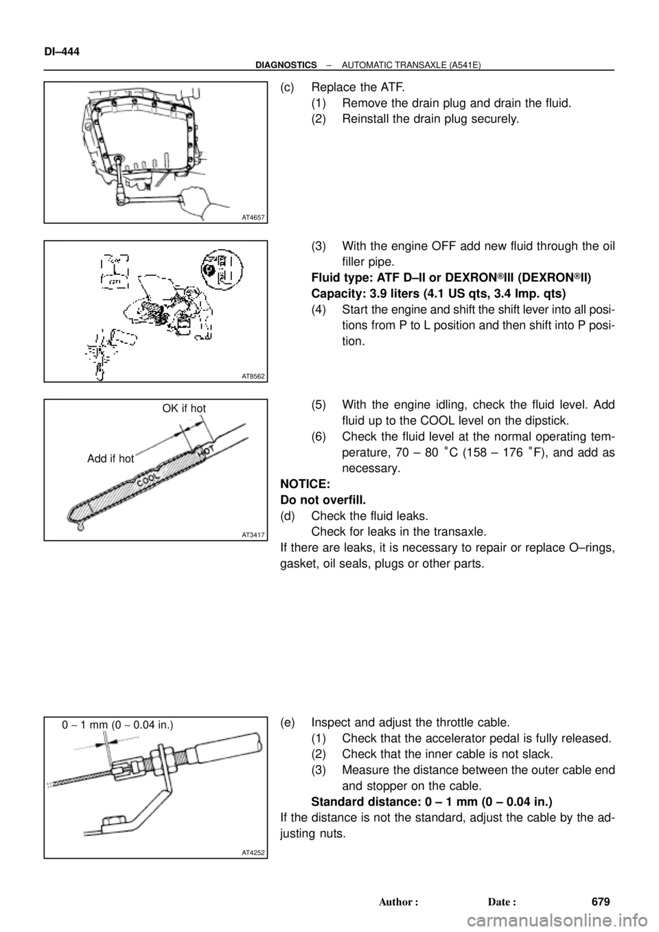
(c) Replace the ATF.
(1) Remove the drain plug and drain the fluid.
(2) Reinstall the drain plug securely.
(3) With the engine OFF add new fluid through the oil
filler pipe.
Fluid type: ATF D±II or DEXRON®III (DEXRON®II)
Capacity: 3.9 liters (4.1 US qts, 3.4 Imp. qts)
(4) Start the engine and shift the shift lever into all posi-
tions from P to L position and then shift into P posi-
tion.
(5) With the engine idling, check the fluid level. Add
fluid up to the COOL level on the dipstick.
(6) Check the fluid level at the normal operating tem-
perature, 70 ± 80 °C (158 ± 176 °F), and add as
necessary.
NOTICE:
Do not overfill.
(d) Check the fluid leaks.
Check for leaks in the transaxle.
If there are leaks, it is necessary to repair or replace O±rings,
gasket, oil seals, plugs or other parts.
(e) Inspect and adjust the throttle cable.
(1) Check that the accelerator pedal is fully released.
(2) Check that the inner cable is not slack.
(3) Measure the distance between the outer cable end
and stopper on the cable.
Standard distance: 0 ± 1 mm (0 ± 0.04 in.)
If the distance is not the standard, adjust the cable by the ad-
justing nuts.