Page 983 of 4592

BE0AJ±04
Z18937
Connector ºAº Connector ºBº Connector ºCº
Connector ºAº
Connector ºBº
Connector ºCº
J±13±1±A J±16±1 J±13±1
1 2 3 4 5 6 7 8 9 10 11 12 1314 15 16 1 234 56 78 910111213 1 23456 78910111213
C7
C5
A2 B3
A1
C8
B15
C6
B6
A4
C4
B5
C10 B14
A13
B2
C1
B1
C9
A6
A11
A7
A10
A8
A9
C13
B8
B11
B12A5
C11
B4
B16 C2
A12
A3
B7
C3
C12
B9
B10
B13 F
E
T
S
ODOMETER
Fuel Level Warning
Seat Belt Warning
ABS Warning
Low Oil Pressure Warning
Cruise Control Indicator
Malfunction Indicator
O/D OFF Indicator
Light Failure Warning
Brake Warning
SLIP Indicator
TRAC Indicator
Washer Level Warning
Discharge Warning
Right Turn Indicator
Left Turn Indicator
Security Indicator
L
2
D
N
R
P
Illumination
Hi±Beam Indicator
Open Door Warning
SRS Warning
: Fuel Gauge
: Engine Coolant Temperature Sender Gauge
: Tachometer
: Speedometer
No.
A
B
C1
2
3
4
5
6
7 8
9
10
11
12 13
14
15
16
2 3
4
5
6
7 8
9
10
11 12
131
2
3
4 5
6
7
8
9
10
11
12
13
F
E
T
SEngine coolant temperature sender gauge
Ground
Light failure sensor
Integration relay
Traction ECU
Park/neutral position switch (A/T)
O/D OFF switch (A/T)
IGN fuse
Turn signal switch
ST relay
ECM
Generator
Oil pressure switch
ECM
Parking brake switch and brake fluid level warning switch
Headlight dimmer switch
Headlight dimmer switch
Door courtesy switch
DOME fuse
ECU±B fuse
Airbag sensor assembly
ECM
No.1 Vehicle speed sensor Ground
Turn signal switch ECM
Traction ECU
ABS ECU
Ground No.1 Vehicle speed sensor
GAUGE fuse
Igniter
Security ECU
Cruise control ECU
Washer fluid level warning switch
Light control rheostat
TAIL fuse Park/neutral position switch (A/T) Park/neutral position switch (A/T) Park/neutral position switch (A/T) Park/neutral position switch (A/T)
Park/neutral position switch (A/T)Wire Harness Side
Bulb Check
Relay
N20107 N201081
BE±4
± BODY ELECTRICALCOMBINATION METER
CIRCUIT
Page 985 of 4592

N20216
C
B
A BE±6
± BODY")
N20215
Engine coolant temperature gauge
Ignition
Switch
BatterySender
Gauge
Z15788
Engine coolant temperature gauge
Ignition
Switch
BatteryWire Harness SideTest Bulb
(3.4 W)
N20216
C
B
A BE±6
± BODY ELECTRICALCOMBINATION METER
6. INSPECT ENGINE COOLANT TEMPERATURE RE-
CEIVER GAUGE OPERATION
(a) Disconnect the connector from the sender gauge.
(b) Turn the ignition switch ON and check that the receiver
gauge needle indicates COOL.
(c) Ground terminal on the wire harness side connector
through a 3.4±W test bulb.
(d) Turn the ignition switch ON, and check that the bulb lights
up and the receiver gauge needle moves to the hot side.
If operation is as specified, replace the sender gauge.
Then, recheck the system.
If operation is not as specified, measure the receiver gauge re-
sistance.
7. INSPECT ENGINE COOLANT TEMPERATURE RE-
CEIVER GAUGE RESISTANCE
Measure the resistance between terminals.
Tester connectionResistance (W) *
A ± BApprox. 175.7
A ± CApprox. 54.0
B ± CApprox. 229.7
*: This circuit includes the diode.
HINT:
Connect the test leads so that the current from the ohmmeter
can flow according to the above order.
If resistance value is not as specified, replace the receiver
gauge.
Page 986 of 4592

I07709
Slide
rheostat35.63 ±
0.1 W35.63 ±
0.1 W
Z14205
Warning Light
Ignition
Switch
Battery
1
N06640
± BODY ELECTRICALCOMBINATION METER
BE±7
8. INSPECT ENGINE COOLANT TEMPERATURE SEND-
ER GAUGE RESISTANCE
Connect the wire harness as shown in the illustration, and ad-
just the ammeter pointer to indicate º0º using the slide rheostat,
then read the rheostat indication.
Temperature °C (°F)Resistance (W)
50 (122.0)160 ± 240
120 (248.0)17.1 ± 21.2
If resistance value is not as specified, replace the engine cool-
ant temperature sender gauge.
9. INSPECT LOW OIL PRESSURE WARNING LIGHT
(a) Disconnect the connector from the warning switch and
ground terminal on the wire harness side connector.
(b) Turn the ignition switch ON and check that the warning
light lights up.
If the warning light does not light up, test the bulb.
10. INSPECT LOW OIL PRESSURE SWITCH
(a) Disconnect the connector from the switch.
(b) Check that continuity exists between terminal and ground
with the engine stopped.
(c) Check that no continuity exists between terminal and
ground with the engine running.
HINT:
Oil pressure should be over 24.5 kPa (0.25 kgf/cm
2, 3.55 psi).
If operation is not as specified, replace the switch.
Page 1141 of 4592
CO066±03
± COOLING (5S±FE)COOLANT
CO±1
1575 Author�: Date�:
COOLANT
INSPECTION
HINT:
Check the coolant level when the engine is cold.
1. CHECK ENGINE COOLANT LEVEL AT RADIATOR RESERVOIR
The engine coolant level should be between the ºLOWº and ºFULLº lines.
If low, check for leaks and add ºToyota Long Life Coolantº or equivalent up to the ºFULLº line.
2. CHECK ENGINE COOLANT QUALITY
(a) Remove the radiator cap.
CAUTION:
To avoid the danger of being burned, do not remove the radiator cap while the engine and radiator
are still hot, as fluid and steam can be blown out under pressure.
(b) There should not be any excessive deposits of rust or scale around the radiator cap or radiator filler
hole, and the coolant should be free from oil.
If excessively dirty, replace the coolant.
(c) Reinstall the radiator cap.
Page 1142 of 4592
COOLANT
1576 Author�: Date�:
REPLACEMENT
1. DRAIN ENGINE COOLANT
(a) Remove the radiator cap.
CAUTION:
To avoid the dang")
CO067±03
Z18990
Radiator Drain Plug
Engine Drain Plug CO±2
± COOLING (5S±FE)COOLANT
1576 Author�: Date�:
REPLACEMENT
1. DRAIN ENGINE COOLANT
(a) Remove the radiator cap.
CAUTION:
To avoid the danger of being burned, do not remove the ra-
diator cap while the engine and radiator are still hot, as fluid
and steam can be blown out under pressure.
(b) Loosen the radiator drain plug (on the right side of the ra-
diator lower tank) and engine drain plug (on the left rear
of the cylinder block), and drain the coolant.
(c) Close the drain plugs.
Torque: 25 N´m (250 kgf´cm, 18 ft´lbf) for engine
2. FILL ENGINE COOLANT
(a) Slowly fill the system with coolant.
�Use of improper coolants may damage engine cool-
ing system.
�Use ºToyota Long Life Coolantº or equivalent and
mix it with plan water according to the manufactur-
er's directions.
�Using of coolant which includes more than 50 %
(freezing protection down to ±35°C (±31°F) or 60 %
(freezing protection down to ±50°C (±58°F)) of eth-
ylene±glycol is recommended but not more than 70
%.
NOTICE:
�Do not use an alcohol type coolant or plain water
alone.
�The coolant should be mixed with plain water (prefer-
ably demineralized water or distilled water).
Capacity:
w/ Oil cooler6.9 litters (7.3 US qts, 6.1 lmp. qts)
w/o Oil cooler6.2 litters (6.5 US qts, 5.4 lmp. qts)
(b) Install the radiator cap.
(c) Start the engine, and bleed the cooling system.
(d) Refill the radiator reservoir with coolant until it reaches the
ºFULLº line.
3. CHECK FOR COOLANT LEAKS
Page 1145 of 4592
CO069±04
S05599
S05924
S05963
1
2
3
± COOLING (5S±FE)WATER PUMP
CO±5
1579 Author�: Date�:
REMOVAL
1. DRAIN ENGINE COOLANT
2. REMOVE TIMING BELT (See page EM±17)
3. DISCONNECT LOWER RADIATOR HOSE FROM WA-
TER OUTLET
4. REMOVE TIMING BELT TENSION SPRING
Loosen the No.1 idler pulley bolt, and remove the tension
spring.
5. REMOVE NO.2 IDLER PULLEY
Remove the bolt and idler pulley.
6. w/ Oil Cooler:
REMOVE A/C COMPRESSOR (See page EM±69)
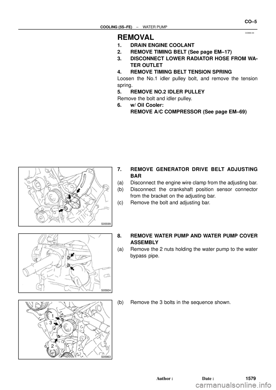
7. REMOVE GENERATOR DRIVE BELT ADJUSTING
BAR
(a) Disconnect the engine wire clamp from the adjusting bar.
(b) Disconnect the crankshaft position sensor connector
from the bracket on the adjusting bar.
(c) Remove the bolt and adjusting bar.
8. REMOVE WATER PUMP AND WATER PUMP COVER
ASSEMBLY
(a) Remove the 2 nuts holding the water pump to the water
bypass pipe.
(b) Remove the 3 bolts in the sequence shown.
Page 1147 of 4592
CO06A±03
S01486
Turn
Air Hole
± COOLING (5S±FE)WATER PUMP
CO±7
1581 Author�: Date�:
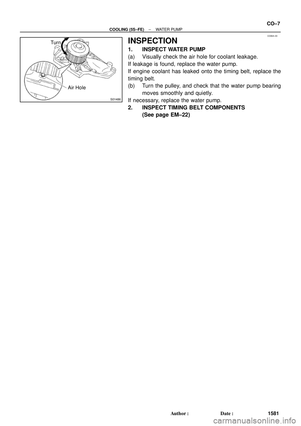
INSPECTION
1. INSPECT WATER PUMP
(a) Visually check the air hole for coolant leakage.
If leakage is found, replace the water pump.
If engine coolant has leaked onto the timing belt, replace the
timing belt.
(b) Turn the pulley, and check that the water pump bearing
moves smoothly and quietly.
If necessary, replace the water pump.
2. INSPECT TIMING BELT COMPONENTS
(See page EM±22)
Page 1149 of 4592
± COOLING (5S±FE)WATER PUMP
CO±9
1583 Author�: Date�:
6. INSTALL TIMING BELT TENSION SPRING
(See page EM±23)
7. CONNECT LOWER RADIATOR HOSE TO WATER IN-
LET
8. INSTALL TIMING BELT (See page EM±23)
9. FILL WITH ENGINE COOLANT
10. START ENGINE AND CHECK FOR COOLANT LEAKS