Page 973 of 4592

BO0NJ±01
AB0152
SST BO±128
± BODYSEAT BELT PRETENSIONER
2476 Author�: Date�:
DISPOSAL
HINT:
When scrapping vehicles equipped with a supplemental re-
straint system or disposing of a front seat outer belt (with seat
belt pretensioner) always first activate the seat belt pretension-
er in accordance with the procedure described below. If any ab-
normality occurs with the seat belt pretensioner operation, con-
tact the SERVICE DEPT. of the DISTRIBUTOR. when
disposing of a front seat outer belt (with seat belt pretensioner)
deployed in a collision, follow the same procedure given in step
1±(d) in ºDISPOSALº.
CAUTION:
�Never dispose of front seat outer belt which has an
undeployed pretensioner.
�The seat belt pretensioner produces a sizeable ex-
ploding sound when it deploys, so perform the opera-
tion out±of±door and where it will not create a nui-
sance to nearby residents.
�When deploying the seat belt pretensioner, always
use the specified SST. (SRS Airbag Deployment Tool)
Perform the operation in a place away from electrical
noise.
SST 09082±00700, 09082±00740
�When deploying a front seat outer belt (with seat belt
pretensioner), perform the operation from at least
10 m (33 ft) away from the front seat outer belt.
�Use gloves and safety glasses when handling a front
seat outer belt with operated pretensioner.
�Always wash your hands with water after completing
the operation.
�Do not apply water, etc. to a front seat outer belt with
operated pretensioner.
Page 974 of 4592

AB0158
SSTBattery
AB0152
SST
AB0158
SSTBattery
H01580
SST
H01346
± BODYSEAT BELT PRETENSIONER
BO±129
2477 Author�: Date�:
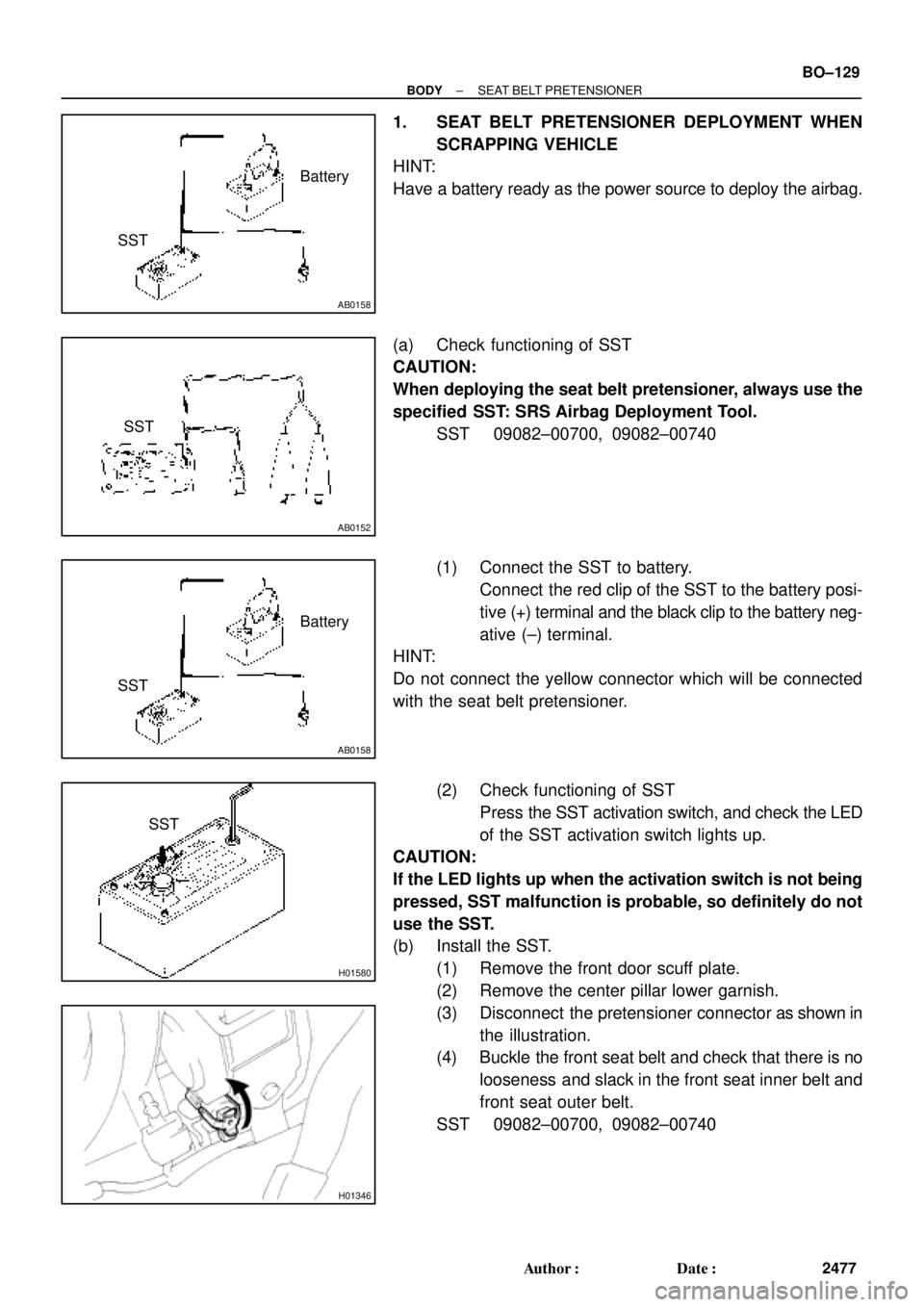
1. SEAT BELT PRETENSIONER DEPLOYMENT WHEN
SCRAPPING VEHICLE
HINT:
Have a battery ready as the power source to deploy the airbag.
(a) Check functioning of SST
CAUTION:
When deploying the seat belt pretensioner, always use the
specified SST: SRS Airbag Deployment Tool.
SST 09082±00700, 09082±00740
(1) Connect the SST to battery.
Connect the red clip of the SST to the battery posi-
tive (+) terminal and the black clip to the battery neg-
ative (±) terminal.
HINT:
Do not connect the yellow connector which will be connected
with the seat belt pretensioner.
(2) Check functioning of SST
Press the SST activation switch, and check the LED
of the SST activation switch lights up.
CAUTION:
If the LED lights up when the activation switch is not being
pressed, SST malfunction is probable, so definitely do not
use the SST.
(b) Install the SST.
(1) Remove the front door scuff plate.
(2) Remove the center pillar lower garnish.
(3) Disconnect the pretensioner connector as shown in
the illustration.
(4) Buckle the front seat belt and check that there is no
looseness and slack in the front seat inner belt and
front seat outer belt.
SST 09082±00700, 09082±00740
Page 975 of 4592

H01880
SST SST
R13455
10 m (33 ft) or more BO±130
± BODYSEAT BELT PRETENSIONER
2478 Author�: Date�:
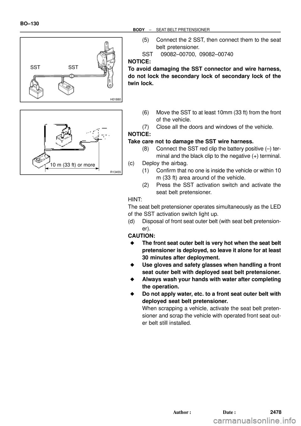
(5) Connect the 2 SST, then connect them to the seat
belt pretensioner.
SST 09082±00700, 09082±00740
NOTICE:
To avoid damaging the SST connector and wire harness,
do not lock the secondary lock of secondary lock of the
twin lock.
(6) Move the SST to at least 10mm (33 ft) from the front
of the vehicle.
(7) Close all the doors and windows of the vehicle.
NOTICE:
Take care not to damage the SST wire harness.
(8) Connect the SST red clip the battery positive (±) ter-
minal and the black clip to the negative (+) terminal.
(c) Deploy the airbag.
(1) Confirm that no one is inside the vehicle or within 10
m (33 ft) area around of the vehicle.
(2) Press the SST activation switch and activate the
seat belt pretensioner.
HINT:
The seat belt pretensioner operates simultaneously as the LED
of the SST activation switch light up.
(d) Disposal of front seat outer belt (with seat belt pretension-
er).
CAUTION:
�The front seat outer belt is very hot when the seat belt
pretensioner is deployed, so leave it alone for at least
30 minutes after deployment.
�Use gloves and safety glasses when handling a front
seat outer belt with deployed seat belt pretensioner.
�Always wash your hands with water after completing
the operation.
�Do not apply water, etc. to a front seat outer belt with
deployed seat belt pretensioner.
When scrapping a vehicle, activate the seat belt preten-
sioner and scrap the vehicle with operated front seat out-
er belt still installed.
Page 983 of 4592

BE0AJ±04
Z18937
Connector ºAº Connector ºBº Connector ºCº
Connector ºAº
Connector ºBº
Connector ºCº
J±13±1±A J±16±1 J±13±1
1 2 3 4 5 6 7 8 9 10 11 12 1314 15 16 1 234 56 78 910111213 1 23456 78910111213
C7
C5
A2 B3
A1
C8
B15
C6
B6
A4
C4
B5
C10 B14
A13
B2
C1
B1
C9
A6
A11
A7
A10
A8
A9
C13
B8
B11
B12A5
C11
B4
B16 C2
A12
A3
B7
C3
C12
B9
B10
B13 F
E
T
S
ODOMETER
Fuel Level Warning
Seat Belt Warning
ABS Warning
Low Oil Pressure Warning
Cruise Control Indicator
Malfunction Indicator
O/D OFF Indicator
Light Failure Warning
Brake Warning
SLIP Indicator
TRAC Indicator
Washer Level Warning
Discharge Warning
Right Turn Indicator
Left Turn Indicator
Security Indicator
L
2
D
N
R
P
Illumination
Hi±Beam Indicator
Open Door Warning
SRS Warning
: Fuel Gauge
: Engine Coolant Temperature Sender Gauge
: Tachometer
: Speedometer
No.
A
B
C1
2
3
4
5
6
7 8
9
10
11
12 13
14
15
16
2 3
4
5
6
7 8
9
10
11 12
131
2
3
4 5
6
7
8
9
10
11
12
13
F
E
T
SEngine coolant temperature sender gauge
Ground
Light failure sensor
Integration relay
Traction ECU
Park/neutral position switch (A/T)
O/D OFF switch (A/T)
IGN fuse
Turn signal switch
ST relay
ECM
Generator
Oil pressure switch
ECM
Parking brake switch and brake fluid level warning switch
Headlight dimmer switch
Headlight dimmer switch
Door courtesy switch
DOME fuse
ECU±B fuse
Airbag sensor assembly
ECM
No.1 Vehicle speed sensor Ground
Turn signal switch ECM
Traction ECU
ABS ECU
Ground No.1 Vehicle speed sensor
GAUGE fuse
Igniter
Security ECU
Cruise control ECU
Washer fluid level warning switch
Light control rheostat
TAIL fuse Park/neutral position switch (A/T) Park/neutral position switch (A/T) Park/neutral position switch (A/T) Park/neutral position switch (A/T)
Park/neutral position switch (A/T)Wire Harness Side
Bulb Check
Relay
N20107 N201081
BE±4
± BODY ELECTRICALCOMBINATION METER
CIRCUIT
Page 989 of 4592
BO2DM±01
± BODYSRS AIRBAG
BO±3
542 Author�: Date�:
SRS AIRBAG
PRECAUTION
The CAMRY CNG is equipped with SRS (Supplemental Restraint System) such as the driver airbag, front
passenger airbag and seat belt pretensioner. Failure to carry out service operation in the correct sequence
could cause the SRS to unexpectedly deploy during servicing, possibly leading to a serious accident. Before
servicing (including removal or installation of parts, inspection or replacement), be sure to read the precau-
tionary notices in the RS section (See Pub. No. RM654U).
Page 1838 of 4592

DI4L1±01
H02309
R13006
DLC1
E1 Tc
DI±626
± DIAGNOSTICSSUPPLEMENTAL RESTRAINT SYSTEM
861 Author�: Date�:
PRE±CHECK
1. SRS WARNING LIGHT CHECK
(a) Turn the ignition switch to the ACC or ON position and
check that the SRS warning light lights up.
(b) Check that the SRS warning light goes out after approx.
6 seconds.
HINT:
�When the ignition switch is at ACC or ON and the SRS
warning light remains on or flashes, the airbag sensor as-
sembly has detected a malfunction code.
�If, after approx. 6 seconds have elapsed, the SRS warn-
ing light sometimes lights up or the SRS warning light
lights up even when the ignition switch is OFF, a short in
the SRS warning light circuit can be considered likely.
Proceed to ºSRS warning light circuit malfunctionº on
page DI±790, DI±792.
2. DTC CHECK (Using diagnosis check wire)
(a) Present troubles codes:
Output the DTC.
(1) Turn the ignition switch to the ACC or ON position
and wait for approx. 20 seconds.
(2) Using SST, connect terminals Tc and E1 of the
DLC1.
SST 09843±18020
NOTICE:
Pay due attention to the terminal connecting position to
avoid a malfunction.
(b) Past troubles codes:
Output the DTC.
(1) Using service wire, connect Terminals Tc and E1 of
the DLC1.
SST 09843±18020
(2) Turn the ignition switch to the ACC or ON position
and wait for approx. 20 seconds.
NOTICE:
Pay due attention to the terminal connecting position to
avoid a malfunction.
Page 1841 of 4592
± DIAGNOSTICSSUPPLEMENTAL RESTRAINT SYSTEM
DI±629
864 Author�: Date�:
7. RELEASE METHOD OF AIRBAG ACTIVATION PRE-
VENTION MECHANISM
An airbag activation prevention mechanism is built into the con-
nector for the squib circuit of the SRS.
When release of the airbag activation prevention mechanism is
directed in the troubleshooting procedure, as shown in the il-
lustration of the connectors on the next pages, insert paper
which is the same thickness as the male terminal, between the
terminal and the short spring.
CAUTION:
Never release the airbag activation prevention mechanism
on the steering wheel pad connector.
NOTICE:
�Do not release the airbag activation prevention mech-
anism unless specifically directed by the trouble-
shooting procedure.
�If the inserted paper is too thick the terminal and short
spring may be damaged, so always use paper with
the same thickness as the male terminal.
Page 1842 of 4592
H08316
TMC made :
Side Airbag Assembly (LH)
(Squib) Side Airbag Sensor (LH)Side Airbag Sensor (RH)Side Airbag Assembly (RH)
(Squib)
Seat Belt
Pretensioner (RH)
Airbag Sensor
AssemblyFront Passenger Airbag Assembly (Squib)
Spiral Cable
No.1 J/B 2
37 8
10
11
12
13
1
4
5
6
9
Steering Wheel
Pad (Squib) Front Airbag Sensor (RH)
Front Airbag Sensor (LH)
Seat Belt
Pretensioner (LH) 14
15
16
DI±630
± DIAGNOSTICSSUPPLEMENTAL RESTRAINT SYSTEM
865 Author�: Date�: