Page 1988 of 4592
H03355H03356H09518
Airbag
Sensor
Assembly Front Airbag
Sensor (RH)
(+)SR+
(±)
SR± Airbag Sensor
Assembly
H03353H09521H03356H09523
Front Airbag
Sensor (RH)
Airbag
Sensor
Assembly
(+)SR+ Airbag Sensor
Assembly
(±)
SR± SR+SR±
DI±776
± DIAGNOSTICSSUPPLEMENTAL RESTRAINT SYSTEM
1011 Author�: Date�:
4 Check wire harness.
CHECK:
For the connector (on the airbag sensor assembly side) be-
tween the front airbag sensor (RH) and the airbag sensor as-
sembly, measure the resistance between SR+ and SR±.
OK:
Resistance: 1 MW or Higher
NG Go to step 10.
OK
5 Check wire harness.
PREPARATION:
Using a service wire, connect SR+ and SR± of the connector
(on the front airbag sensor (RH) side) between the airbag sen-
sor assembly and the front airbag sensor (RH).
CHECK:
For the connector (on the airbag sensor assembly side) be-
tween the front airbag sensor (RH) and the airbag sensor as-
sembly, measure the resistance between SR+ and SR±.
OK:
Resistance: Below 1 W
NG Go to step 11.
OK
Page 1989 of 4592
H04504H01062H08346
Airbag
Sensor
Assembly Front Airbag
Sensor (RH)
(+) SR+
(±)SR±
± DIAGNOSTICSSUPPLEMENTAL RESTRAINT SYSTEM
DI±777
1012 Author�: Date�:
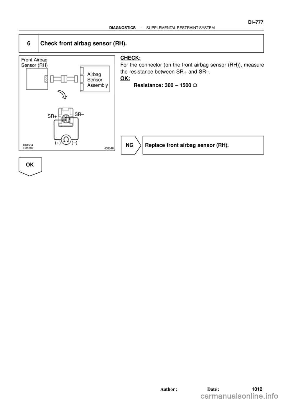
6 Check front airbag sensor (RH).
CHECK:
For the connector (on the front airbag sensor (RH)), measure
the resistance between SR+ and SR±.
OK:
Resistance: 300 ± 1500 W
NG Replace front airbag sensor (RH).
OK
Page 1990 of 4592

Airbag
Sensor
Assembly
ON
or
DTC B1156/B1157/15 ACC
DLC1
E1
Tc
\"u \"u
DI±778
± DIAGNOSTICSSUPPLEMENTAL RESTRAINT SYSTEM
1013 Author�: Dat")
H02757AB0118AB0119R13006H01063H04014
Front Airbag
Sensor (RH)
Airbag
Sensor
Assembly
ON
or
DTC B1156/B1157/15 ACC
DLC1
E1
Tc
"u "u
DI±778
± DIAGNOSTICSSUPPLEMENTAL RESTRAINT SYSTEM
1013 Author�: Date�:
7 Check airbag sensor assembly.
PREPARATION:
(a) Turn ignition switch to LOCK.
(b) Disconnect negative (±) terminal cable from the battery,
and wait at least for 90 seconds.
(c) Connect the front airbag sensor (RH) connector and air-
bag sensor assembly connector.
(d) Connect negative (±) terminal cable to the battery, and
wait at least for 2 seconds.
CHECK:
(a) Turn ignition switch to ACC or ON, and wait at least for 20
seconds.
(b) Clear DTC stored in memory.
(See Pub. No. RM572E1 on page DI±95)
(c) Turn ignition switch to LOCK, and wait at least for 20 se-
conds.
(d) Turn ignition switch to ACC or ON, and wait at least for 20
seconds.
(e) Check DTC.
(See Pub. No. RM572E1 on page DI±95)
OK:
DTC B1156/B1157/15 is not output.
HINT:
Codes other than code B1156/B1157/15 may be output at this
time, but they are not relevant to this check.
NG Replace airbag sensor assembly.
OK
From the results of the above inspection, the malfunctioning part can now be considered normal.
To make sure of this, use the simulation method to check.
Page 1991 of 4592

(+)
SR+
(±)
SR±
ON
Engine Room Main
Wire Harness
u\"
H03354H06140H08258
Airbag
Sensor
Assembly Front Airbag
Sensor (RH)
(+)S")
H03354
H06141AB0119H08272
Airbag
Sensor
Assembly Front Airbag
Sensor (RH)
(+)
SR+
(±)
SR±
ON
Engine Room Main
Wire Harness
u"
H03354H06140H08258
Airbag
Sensor
Assembly Front Airbag
Sensor (RH)
(+)SR+
(±)SR± Engine Room Main
Wire Harness
± DIAGNOSTICSSUPPLEMENTAL RESTRAINT SYSTEM
DI±779
1014 Author�: Date�:
8 Check engine room main wire harness (to B+).
PREPARATION:
Disconnect the engine room main wire harness connector on
the airbag sensor assembly side.
CHECK:
(a) Turn ignition switch to ON.
(b) For the connector (on the RH front door wire harness
side) between the airbag sensor assembly and the en-
gine room main wire harness, measure the voltage be-
tween body ground and each of SR+ and SR±.
OK:
Voltage: Below 1 V
NG Repair or replace engine room main wire har-
ness.
OK
Repair or replace harness or connector between airbag sensor assembly and engine room main
wire harness.
9 Check engine room main wire harness (to ground).
PREPARATION:
Disconnect the engine room main wire harness connector on
the airbag sensor assembly side.
CHECK:
For the connector (on the engine room main wire harness side)
between the airbag sensor assembly and the engine room main
wire harness, measure the resistance between body ground
and each of SR+ and SR±.
OK:
Resistance: 1 MW or Higher
NG Repair or replace engine room main wire har-
ness.
OK
Repair or replace harness or connector between airbag sensor assembly and engine room main
wire harness.
Page 1992 of 4592
H03354H09519H09520
Airbag
Sensor
Assembly
Front Airbag
Sensor (RH)
(±) SR+SR±
Engine Room Main
Wire Harness
(+)
u "
DI±780
± DIAGNOSTICSSUPPLEMENTAL RESTRAINT SYSTEM
1015 Author�: Date�:
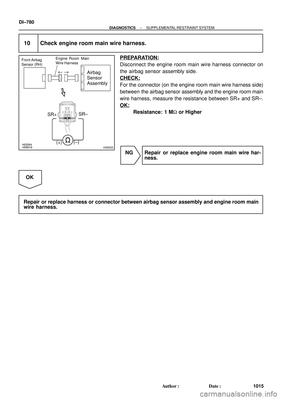
10 Check engine room main wire harness.
PREPARATION:
Disconnect the engine room main wire harness connector on
the airbag sensor assembly side.
CHECK:
For the connector (on the engine room main wire harness side)
between the airbag sensor assembly and the engine room main
wire harness, measure the resistance between SR+ and SR±.
OK:
Resistance: 1 MW or Higher
NG Repair or replace engine room main wire har-
ness.
OK
Repair or replace harness or connector between airbag sensor assembly and engine room main
wire harness.
Page 1993 of 4592
H03352H09519H09521H09522
Airbag
Sensor
Assembly Front Airbag
Sensor (RH)
(+) SR+
(±)SR±
Engine Room Main
Wire Harness
SR+
SR±
u "
± DIAGNOSTICSSUPPLEMENTAL RESTRAINT SYSTEM
DI±781
1016 Author�: Date�:
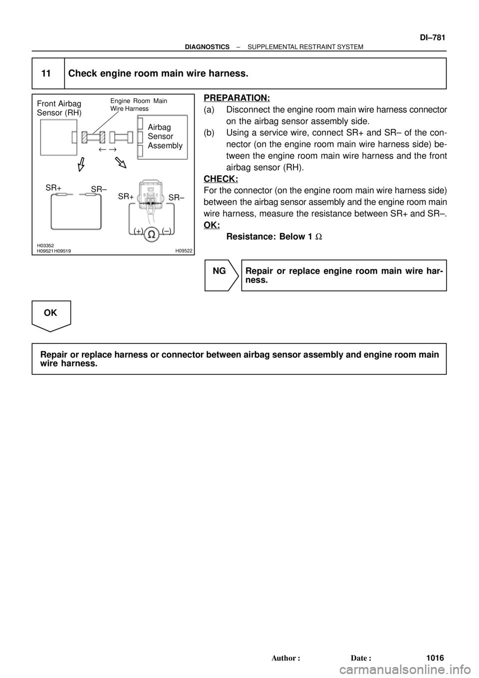
11 Check engine room main wire harness.
PREPARATION:
(a) Disconnect the engine room main wire harness connector
on the airbag sensor assembly side.
(b) Using a service wire, connect SR+ and SR± of the con-
nector (on the engine room main wire harness side) be-
tween the engine room main wire harness and the front
airbag sensor (RH).
CHECK:
For the connector (on the engine room main wire harness side)
between the airbag sensor assembly and the engine room main
wire harness, measure the resistance between SR+ and SR±.
OK:
Resistance: Below 1 W
NG Repair or replace engine room main wire har-
ness.
OK
Repair or replace harness or connector between airbag sensor assembly and engine room main
wire harness.
Page 1994 of 4592
H02751
Airbag Sensor Assembly Front Airbag Sensor (LH)
SL+
SL± C1815
26 2
1 SL+W±R
BR
SL± C18 DI±782
± DIAGNOSTICSSUPPLEMENTAL RESTRAINT SYSTEM
1017 Author�: Date�:
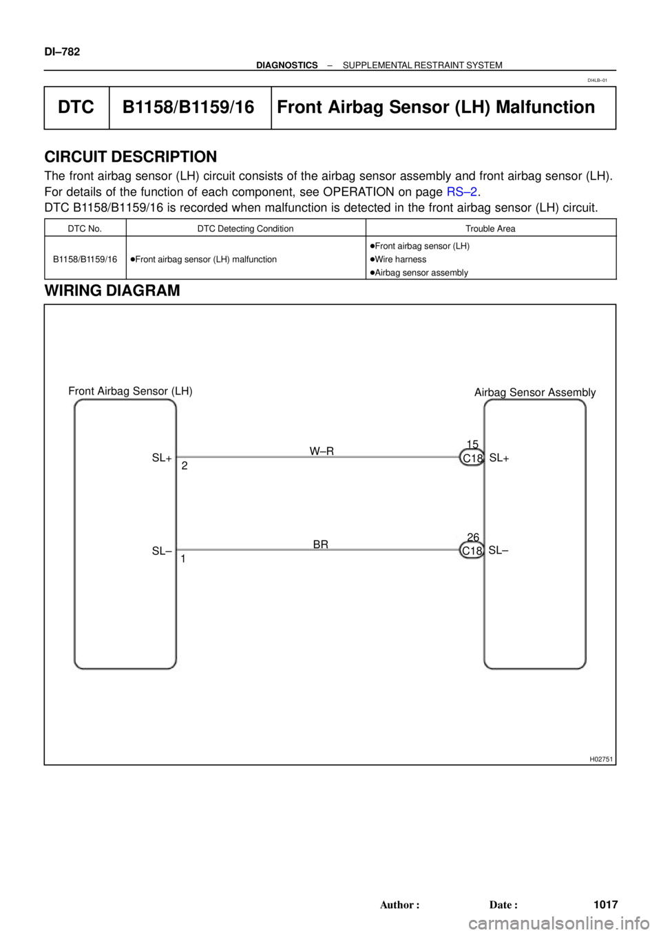
DTC B1158/B1159/16 Front Airbag Sensor (LH) Malfunction
CIRCUIT DESCRIPTION
The front airbag sensor (LH) circuit consists of the airbag sensor assembly and front airbag sensor (LH).
For details of the function of each component, see OPERATION on page RS±2.
DTC B1158/B1159/16 is recorded when malfunction is detected in the front airbag sensor (LH) circuit.
DTC No.DTC Detecting ConditionTrouble Area
B1158/B1159/16�Front airbag sensor (LH) malfunction
�Front airbag sensor (LH)
�Wire harness
�Airbag sensor assembly
WIRING DIAGRAM
DI4LB±01
Page 1995 of 4592

(+)SL+
(±)
SL± Airbag Sensor
Assembly
ON
H08399H01370
H08400
Airbag
Sensor
Assembly
Front Airbag
Sensor (LH)
(+)SL+
(±)
SL�")
H01370AB0119H08065H08066
Airbag
Sensor
Assembly
Front Airbag
Sensor (LH)
(+)SL+
(±)
SL± Airbag Sensor
Assembly
ON
H08399H01370
H08400
Airbag
Sensor
Assembly
Front Airbag
Sensor (LH)
(+)SL+
(±)
SL± Airbag Sensor
Assembly
± DIAGNOSTICSSUPPLEMENTAL RESTRAINT SYSTEM
DI±783
1018 Author�: Date�:
INSPECTION PROCEDURE
1 Prepare for inspection. (See step 1 on page DI±787)
2 Check wire harness (to B+).
CHECK:
(a) Turn ignition switch to ON.
(b) For the connector (on the airbag sensor assembly side)
between the front airbag sensor (LH) and the airbag sen-
sor assembly, measure the voltage between body ground
and each of SL+ and SL±.
OK:
Voltage: Below 1 V
NG Repair or replace harness or connector be-
tween front airbag sensor (LH) and airbag sen-
sor assembly.
OK
3 Check wire harness (to ground).
CHECK:
For the connector (on the airbag sensor assembly side) be-
tween the front airbag sensor (LH) and the airbag sensor as-
sembly, measure the resistance between body ground and
each of SL+ and SL±.
OK:
Resistance: 1 MW or Higher
NG Repair or replace harness or connector be-
tween front airbag sensor (LH) and airbag sen-
sor assembly.
OK

(+)SR+
(±)
SR± Airbag Sensor
Assembly
H03353H09521H03356H09523
Front Airbag
Sensor (RH)
Airbag
Sensor
Assembly
(+)SR+ Airbag Sensor")