Page 1980 of 4592
H01058H01050
H01010
H01166
Airbag
Sensor
Assembly
(±)(+)
SSL+ Airbag Sensor
Assembly
ESL SSL+
ESL
Side Airbag Sensor
Assembly (LH)u"
DI±768
± DIAGNOSTICSSUPPLEMENTAL RESTRAINT SYSTEM
1003 Author�: Date�:
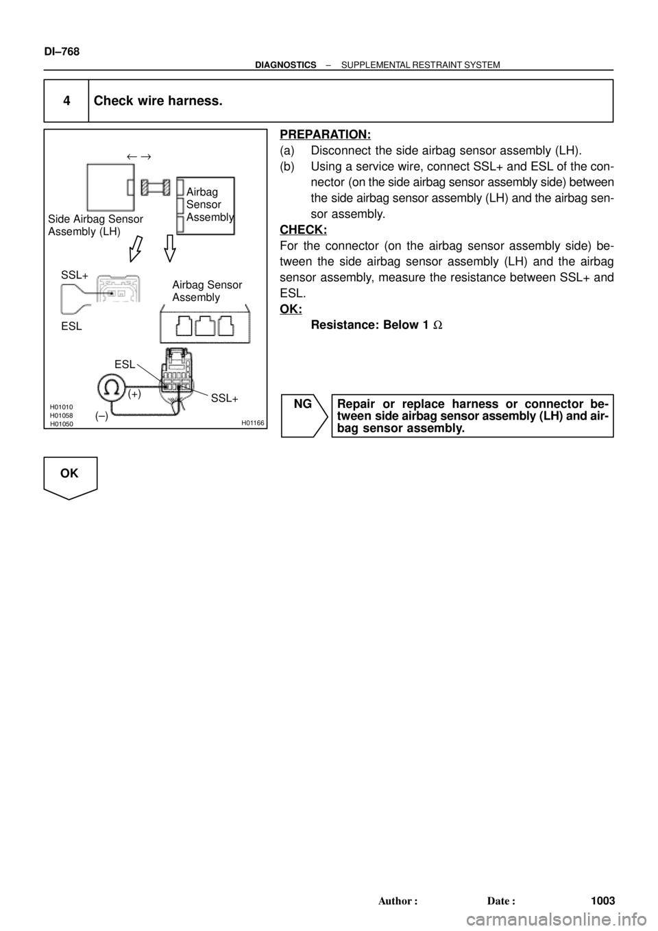
4 Check wire harness.
PREPARATION:
(a) Disconnect the side airbag sensor assembly (LH).
(b) Using a service wire, connect SSL+ and ESL of the con-
nector (on the side airbag sensor assembly side) between
the side airbag sensor assembly (LH) and the airbag sen-
sor assembly.
CHECK:
For the connector (on the airbag sensor assembly side) be-
tween the side airbag sensor assembly (LH) and the airbag
sensor assembly, measure the resistance between SSL+ and
ESL.
OK:
Resistance: Below 1 W
NG Repair or replace harness or connector be-
tween side airbag sensor assembly (LH) and air-
bag sensor assembly.
OK
Page 1981 of 4592
H01010H01059H01051H01167
Airbag
Sensor
Assembly
(±)(+) Side Airbag Sensor
Assembly (LH)
VUPL Airbag Sensor
Assembly
VUPL
FSL
FSL
± DIAGNOSTICSSUPPLEMENTAL RESTRAINT SYSTEM
DI±769
1004 Author�: Date�:
5 Check wire harness.
PREPARATION:
Using a service wire, connect VUPL and FSL of the connector
(on the side airbag sensor assembly side) between the side air-
bag sensor assembly (LH) and the airbag sensor assembly.
CHECK:
For the connector (on the airbag sensor assembly side) be-
tween the side airbag sensor assembly (LH) and the airbag
sensor assembly, measure the resistance between VUPL and
FSL.
OK:
Resistance: Below 1 W
NG Repair or replace harness or connector be-
tween side airbag sensor assembly (LH) and air-
bag sensor assembly.
OK
Page 1982 of 4592

Airbag Sensor Assembly
VUPL
(±) (+)SSL+
FSL
H01008
H01053AB0119H08271
Airbag
Sensor
Assembly Side Airbag Sensor
Assembly (L")
H01052H01008H01168
Airbag
Sensor
Assembly SIde Airbag Sensor Assembly
(LH)
Airbag Sensor Assembly
VUPL
(±) (+)SSL+
FSL
H01008
H01053AB0119H08271
Airbag
Sensor
Assembly Side Airbag Sensor
Assembly (LH)
Airbag Sensor Assembly
VUPL
(±)
(+) SSL+ FSLESLON
DI±770
± DIAGNOSTICSSUPPLEMENTAL RESTRAINT SYSTEM
1005 Author�: Date�:
6 Check wire harness (to ground).
CHECK:
For the connector (on the airbag sensor assembly side) be-
tween the side airbag sensor assembly (LH) and the airbag
sensor assembly, measure the resistance between body
ground and each of SSL+, VUPL and FSL.
OK:
Resistance: 1 MW or Higher
NG Repair or replace harness or connector be-
tween side airbag sensor assembly (LH) and air-
bag sensor assembly.
OK
7 Check wire harness (to B+).
CHECK:
(a) Turn ignition switch to ON.
(b) For the connector (on the airbag sensor assembly side)
between the side airbag sensor assembly (LH) and the
airbag sensor assembly, measure the voltage between
body ground and each of SSL+, ESL, VUPL and FSL.
OK:
Voltage: 0 V
NG Repair or replace harness or connector be-
tween side airbag sensor assembly (LH) and air-
bag sensor assembly.
OK
Page 1983 of 4592

E1
Tc ACCON
or
\" u
DLC1 DTC B1141/33\" u
± DIAGNOSTICSSUPPLEMENTAL RESTRAINT SYSTEM
DI±771
1006 Author�:")
AB0118
R13006AB0119H01007
H01066H01170
Airbag
Sensor
Assembly Side Airbag Sensor Assembly (LH)
E1
Tc ACCON
or
" u
DLC1 DTC B1141/33" u
± DIAGNOSTICSSUPPLEMENTAL RESTRAINT SYSTEM
DI±771
1006 Author�: Date�:
8 Is DTC B1141/33 out put again?
PREPARATION:
(a) Connect the connector to the side airbag sensor assem-
bly (LH).
(b) Connect the connector to the airbag sensor assembly.
(c) Connect negative (±) terminal cable to the battery, and
wait at least for 2 seconds.
CHECK:
(a) Turn ignition switch to ACC or ON, and wait at least for 20
seconds.
(b) Clear DTC stored in memory.
(See step 5 on page DI±626)
(c) Turn ignition switch to LOCK, and wait at least for 20 se-
conds.
(d) Turn ignition switch to ACC or ON, and wait at least for 20
seconds.
(e) Check DTC.
(See page DI±626)
OK:
DTC B1141/33 is not output.
HINT:
Codes other than code B1141/33 may be output at this time, but
they are not relevant to this check.
NO Go to step 9.
YES
From the results of the above inspection, the malfunctioning part can now be considered normal.
To make sure of this, use the simulation method to check.
Page 1984 of 4592

E1
Tc ACCON
or
DLC1 DTC B1141/33\" u
DI±772
± DIAGNOSTICSSUPPLEMENTAL RESTRAINT SYSTEM
1007 Author�: Dat")
AB0118
R13006AB0119H01007
H01066H01170
Airbag
Sensor
Assembly
Side Airbag Sensor
Assembly (RH)
E1
Tc ACCON
or
DLC1 DTC B1141/33" u
DI±772
± DIAGNOSTICSSUPPLEMENTAL RESTRAINT SYSTEM
1007 Author�: Date�:
9 Check airbag sensor assembly.
PREPARATION:
(a) Turn ignition switch to LOCK.
(b) Disconnect negative (±) terminal cable from the battery,
and wait at least for 90 seconds.
(c) Disconnect the side airbag sensor (LH) from the connec-
tor and connect the side airbag sensor (RH) to the con-
nector.
(d) Connect negative (±) terminal cable to the battery, and
wait at least for 2 seconds.
CHECK:
(a) Turn ignition switch to ACC or ON, and wait at least for 20
seconds.
(b) Clear DTC stored in memory.
(See step 5 on page DI±626)
(c) Turn ignition switch to LOCK, and wait at least for 20 se-
conds.
(d) Turn ignition switch to ACC or ON, and wait at least for 20
seconds.
(e) Check DTC.
(See page DI±626)
OK:
DTC B1141/33 is not output.
HINT:
Codes other than code B1141/33 may be output at this time, but
they are not relevant to this check.
NG Replace airbag sensor assembly.
OK
Page 1985 of 4592

E1 TcACCON
or
DLC1
DTC B1140/32 \" u
± DIAGNOSTICSSUPPLEMENTAL RESTRAINT SYSTEM
DI±773
1008 Author�: Dat")
AB0118
R13006AB0119H01012
H01065H01164
Airbag
Sensor
Assembly Side Airbag Sensor
Assembly (LH)
E1 TcACCON
or
DLC1
DTC B1140/32 " u
± DIAGNOSTICSSUPPLEMENTAL RESTRAINT SYSTEM
DI±773
1008 Author�: Date�:
10 Check side airbag sensor assembly (LH).
PREPARATION:
(a) Turn ignition switch to LOCK.
(b) Disconnect negative (±) terminal cable from the battery,
and wait at least for 90 seconds.
(c) Connect the side airbag sensor (LH) to the connector that
the side airbag sensor (RH) was connected to.
(d) Connect negative (±) terminal cable to the battery, and
wait at least for 2 seconds.
CHECK:
(a) Turn ignition switch to ACC or ON, and wait at least for 20
seconds.
(b) Clear DTC stored in memory.
(See page DI±626)
(c) Turn ignition switch to LOCK, and wait at least for 20 se-
conds.
(d) Turn ignition switch to ACC or ON, and wait at least for 20
seconds.
(e) Check DTC.
(See page DI±626)
OK:
DTC B1140/32 is not output.
HINT:
Codes other than code B1140/32 may be output at this time, but
they are not relevant to this check.
NG Replace side airbag sensor assembly (LH).
OK
From the results of the above inspection, the malfunctioning part can now be considered normal.
To make sure of this, use the simulation method to check.
Page 1986 of 4592
H02750
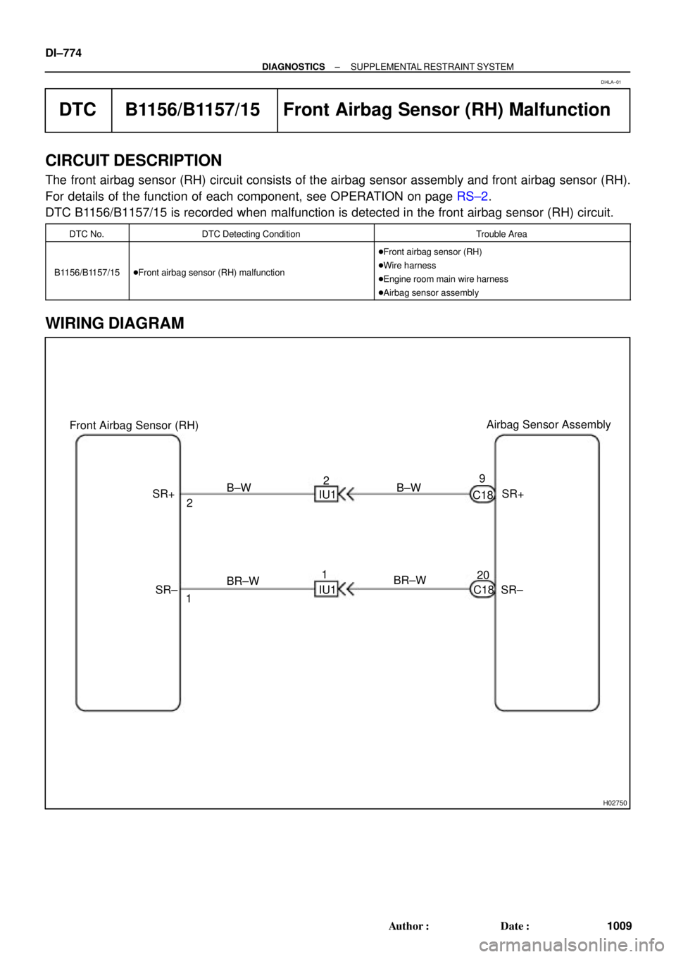
Airbag Sensor Assembly
Front Airbag Sensor (RH)
SR+
SR± C18
C189
20 B±W
BR±W IU12
1 B±W
BR±W 2
1 SR+
SR± IU1 DI±774
± DIAGNOSTICSSUPPLEMENTAL RESTRAINT SYSTEM
1009 Author�: Date�:
DTC B1156/B1157/15 Front Airbag Sensor (RH) Malfunction
CIRCUIT DESCRIPTION
The front airbag sensor (RH) circuit consists of the airbag sensor assembly and front airbag sensor (RH).
For details of the function of each component, see OPERATION on page RS±2.
DTC B1156/B1157/15 is recorded when malfunction is detected in the front airbag sensor (RH) circuit.
DTC No.DTC Detecting ConditionTrouble Area
B1156/B1157/15�Front airbag sensor (RH) malfunction
�Front airbag sensor (RH)
�Wire harness
�Engine room main wire harness
�Airbag sensor assembly
WIRING DIAGRAM
DI4LA±01
Page 1987 of 4592
H03363
H03355AB0119H03445
Airbag
Sensor
Assembly
Front Airbag
Sensor (RH)
(+)SR+
(±)
SR± Airbag Sensor
Assembly
ON
H03361H03353H03443
Airbag
Sensor
Assembly
Front Airbag
Sensor (RH)
(+)SR+
(±)
SR± Airbag Sensor
Assembly
± DIAGNOSTICSSUPPLEMENTAL RESTRAINT SYSTEM
DI±775
1010 Author�: Date�:
INSPECTION PROCEDURE
1 Prepare for inspection. (See step 1 on page DI±787)
2 Check wire harness (to B+).
CHECK:
(a) Turn ignition switch to ON.
(b) For the connector (on the airbag sensor assembly side)
between the front airbag sensor (RH) and the airbag sen-
sor assembly, measure the voltage between body ground
and each of SR+ and SR±.
OK:
Voltage: Below 1 V
NG Go to step 8.
OK
3 Check wire harness (to ground).
CHECK:
For the connector (on the airbag sensor assembly side) be-
tween the front airbag sensor (RH) and the airbag sensor as-
sembly, measure the resistance between body ground and
each of SR+ and SR±.
OK:
Resistance: 1 MW or Higher
NG Go to step 9.
OK


(+)SR+
(±)
SR± Airbag Sensor
Assembly
ON
H03361H03353H03443
Airbag
Sensor
Assembly
Front Airbag
Sensor (RH)
(+)SR+
(±)
SR�")