Page 450 of 4592
AUTOMATIC TRANSAXLEDESCRIPTION ±
AX±1
DESCRIPTION
GENERAL SPECIFICATIONS
Type of TransaxleA541E
Type of Engine1MZ±FE
Torque Converter Clutch Stall Torque Ratio1.8 : 1
Torque Converter Clutch Lock±up MechanismEquipped
Gear Ratio 1st Gear
2nd Gear
3rd Gear
O/D Gear
Reverse Gear2.810
1.549
1.000
0.735
2.296
Transaxle Number of Discs and Plates
O/D Direct Clutch (C
0)
Forward Clutch (C
1)
Direct Clutch (C
2)
2nd Brake (B
2)
First and Reverse Brake (B
3)
O/D Brake (B
0)
2 / 2
5 / 5
3 / 3
3 / 3
6 / 6
3 / 3
B1 Band Width mm (in.)25 (0.98)
ATF TypeATF D±@@@@@: [g 2] or DEXRON®@@@@@: [g
3](DEXRON®@@@@@: [g 2])
Capacity liter (US qts, Imp.qts) A/T
D/F6.75(7.1, 5.9)
0.85 (0.9, 0.7)
AX0CH±05
Page 538 of 4592
AUTOMATIC TRANSAXLEUPPER VALVE BODY ±
AX±89
RETAINERS, PIN, AND CHECK BALLS LOCATION
1. PIN, RETAINERS
MarkNameHeight / Width / Thickness
mm (in.)
@@@@@: [c A]B1 Orifice Control Valve8.9 (0.350) / 5.0 (0.197) / 3.2 (0.126)
@@@@@: [c B]Low Coast Modulator Valve8.5 (0.335) / 5.0 (0.197) / 3.2 (0.126)
2. CHECK BALLS
AX0GZ±02
Page 542 of 4592
AUTOMATIC TRANSAXLELOWER VALVE BODY ±
AX±93
RETAINERS AND CHECK BALLS LOCATION
1. RETAINERS
MarkNameHeight / Width / Thickness mm (in.)
@@@@@: [c A]Accumulator Control Valve8.5 (0.335) / 5.0 (0.197) / 3.2 (0.126)
@@@@@: [c B]2±3 Shift Valve8.5 (0.335) / 5.0 (0.197) / 3.2 (0.126)
@@@@@: [c C]1±2 Shift Valve8.5 (0.335) / 5.0 (0.197) / 3.2 (0.126)
@@@@@: [c D]Reverse Control Valve8.5 (0.335) / 5.0 (0.197) / 3.2 (0.126)
@@@@@: [c E]Cut±Back Valve6.5 (0.256) / 5.0 (0.197) / 3.2 (0.126)
@@@@@: [c F]Secondary Regulator Valve11.0 (0.433) / 5.0 (0.197) / 3.2 (0.126)
@@@@@: [c G]Solenoid Modulator Valve8.5 (0.335) / 5.0 (0.197) / 3.2 (0.126)
@@@@@: [c H]Lock±Up Control Valve9.2 (0.362) / 5.0 (0.197) / 3.2 (0.126)
@@@@@: [c I]Second Coast Modulator Valve8.0 (0.315) / 5.0 (0.197) / 3.2 (0.126)
@@@@@: [c J]Second Lock Valve9.2 (0.362) / 11.5 (0.453) / 3.2 (0.126)
@@@@@: [c K]3±4 Shift Valve6.5 (0.256) / 5.0 (0.197) / 3.2 (0.126)
2. CHECK BALLS
Upper Side
AX0TY±01
Page 578 of 4592
Total No. of coils / Color
Upper valve body
Low coast modulator valve20.2 (0.79")
AUTOMATIC TRANSAXLESERVICE SPECIFICATIONS ±
AX±129
Valve Body Spring
SpringFree length / Coil outer diameter
mm (in.)Total No. of coils / Color
Upper valve body
Low coast modulator valve20.2 (0.795) / 7.9 (0.311)11.9 / Purple
B1 orifice control valve24.8 (0.976) / 6.4 (0.252)12.0 / White
Down±shift plug15.0 (0.591) / 11.0 (0.433)7.0 / None
Throttle valve31.5 (1.240) / 7.0 (0.276)11.4 / Green
Lock±up relay valve26.8 (1.055) / 10.2 (0.402)10.8 / Yellow
Lower valve body
2±3 shift valve28.0 (1.102) / 9.4 (0.370)10.3 / None
Second coast modulator valve20.2 (0.795) / 7.9 (0.311)11.9 / Purple
Accumulator control vavle25.1 (0.988) / 8.6 (0.339)8.0 / Red
Secondary regulator valve46.9 (1.846) / 5.9 (0.232)21.8 / None
Second lock valve20.7 (0.815) / 7.4 (0.291)9.5 / None
Reverse control valve38.1 (1.500) / 6.5 (0.256)19.0 / White/Purple
1±2 shift valve29.2 (1.150) / 8.9 (0.350)12.0 / Light Green
3±4 shift valve28.0 (1.102) / 7.6 (0.299)10.3 / None
Primary regulator valve36.6 (1.441) / 16.1 (0.634)6.3 / None
Cut±back valve21.8 (0.858) / 6.0 (0.236)13.5 / None
Solenoid modulator valve30.2 (1.189) / 5.6 (0.220)15.3 / Purple/Pink
Valve Body Key
KeyHeight
mm (in.)Width
mm (in.)Thickness
mm (in.)
Upper valve body
B1 orifice control valve8.9 (0.350)5.0 (0.197)3.2 (0.126)
Low coast modulator valve8.5 (0.335)5.0 (0.197)3.2 (0.126)
Lower valve body
Accumulator control valve8.5 (0.335)5.0 (0.197)3.2 (0.126)
Secondary regulator valve11.0 (0.433)5.0 (0.197)3.2 (0.126)
1±2 shift valve8.5 (0.335)5.0 (0.197)3.2 (0.126)
2±3 shift valve8.5 (0.335)5.0 (0.197)3.2 (0.126)
3±4 shift valve6.5 (0.256)5.0 (0.197)3.2 (0.126)
Second lock valve9.2 (0.362)5.0 (0.197)3.2 (0.126)
Second coast modulator valve8.0 (0.315)5.0 (0.197)3.2 (0.126)
Reverse control valve8.5 (0.335)5.0 (0.197)3.2 (0.126)
Cut±back valve9.2 (0.362)5.0 (0.197)3.2 (0.126)
Solenoid modulator valve8.5 (0.335)5.0 (0.197)3.2 (0.126)
Lock±up control valve9.2 (0.315)5.0 (0.197)3.2 (0.126)
Page 1137 of 4592
CL03L±01
Q10090
1MZ±FE:
5S±FE:
CL0373
CL0372
Z09915
AB
± CLUTCHCLUTCH UNIT
CL±19
1798 Author�: Date�:
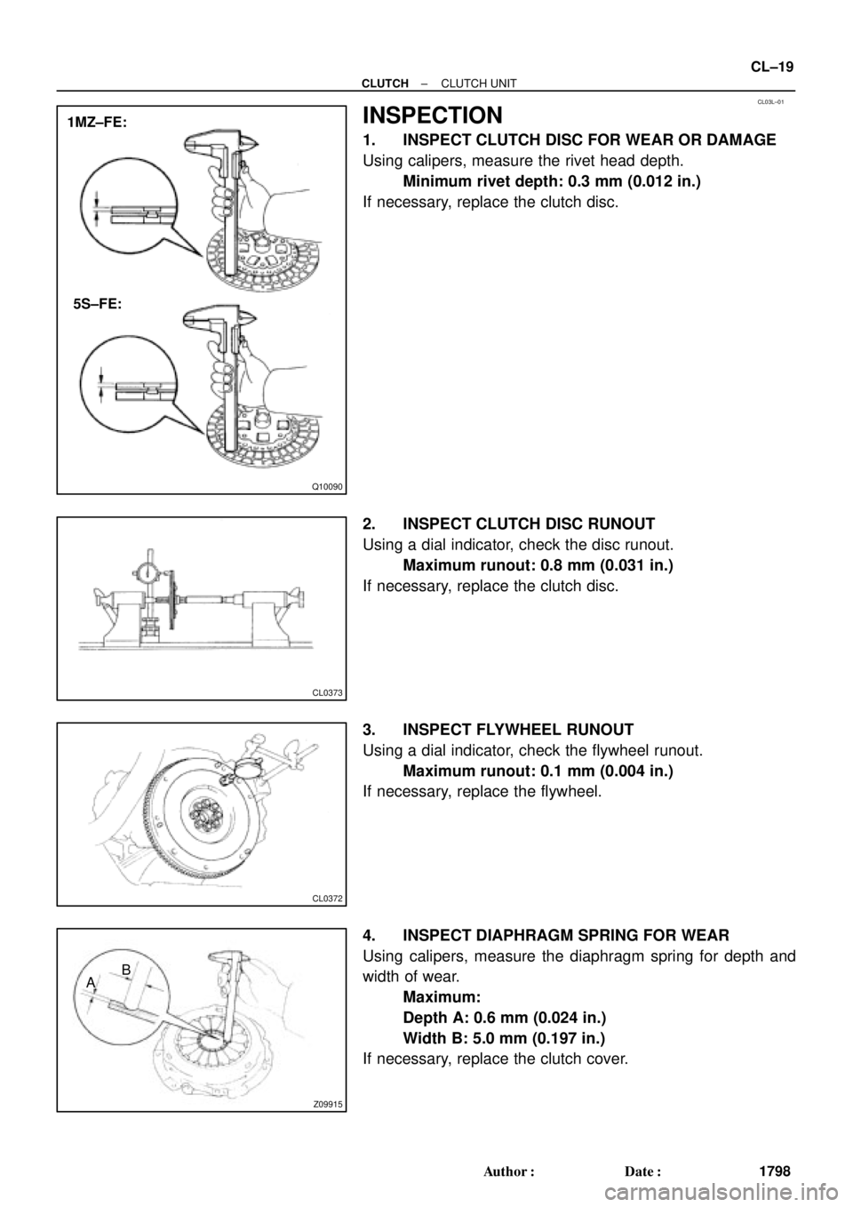
INSPECTION
1. INSPECT CLUTCH DISC FOR WEAR OR DAMAGE
Using calipers, measure the rivet head depth.
Minimum rivet depth: 0.3 mm (0.012 in.)
If necessary, replace the clutch disc.
2. INSPECT CLUTCH DISC RUNOUT
Using a dial indicator, check the disc runout.
Maximum runout: 0.8 mm (0.031 in.)
If necessary, replace the clutch disc.
3. INSPECT FLYWHEEL RUNOUT
Using a dial indicator, check the flywheel runout.
Maximum runout: 0.1 mm (0.004 in.)
If necessary, replace the flywheel.
4. INSPECT DIAPHRAGM SPRING FOR WEAR
Using calipers, measure the diaphragm spring for depth and
width of wear.
Maximum:
Depth A: 0.6 mm (0.024 in.)
Width B: 5.0 mm (0.197 in.)
If necessary, replace the clutch cover.
Page 1375 of 4592

DI±163
398 Author�: Date�:
DTC P1300 Igniter Circuit Malfunction No.1
DTC P1310 Igniter Circuit Malfunction No.2
CIRCUIT DESCRIPTION
The ECM determines the ignition timi")
± DIAGNOSTICSENGINE (5S±FE)
DI±163
398 Author�: Date�:
DTC P1300 Igniter Circuit Malfunction No.1
DTC P1310 Igniter Circuit Malfunction No.2
CIRCUIT DESCRIPTION
The ECM determines the ignition timing, turns on Tr1 at a predetermined angle (°CA) before the desired
ignition timing and outputs and ignition signal (IGT) 1 to the igniter.
Since the width of the IGT signal is constant, the dwell angle control circuit in the igniter determines the time
the control circuit starts primary current flow to the ignition coil based on the engine rpm and ignition timing
one revolution ago, that is, the time the Tr2 turns on.
When it reaches the ignition timing, the ECM turns Tr1 off and outputs the IGT signal O.
This turns Tr2 off, interrupting the primary current flow and generating a high voltage in the secondary coil
which causes the spark plug to spark. Also, by the counter electromotive force generated when the primary
current is interrupted, the igniter sends an ignition confirmation signal (IGF) to the ECM. The ECM stops fuel
injection as a fail safe function when the IGF signal is not input to the ECM.
DTC No.DTC Detecting ConditionTrouble Area
P1300No IGF signal to ECM for 4 consecutive IGT1 signals during
engine running�Open or short in IGF or IGT circuit from igniter to ECM
�Ignition coil No.1 (Igniter No.1)
�ECM
P1310No IGF signal to ECM for 4 consecutive IGT2 signals during
engine running�Open or short in IGF or IGT circuit from igniter to ECM
�Ignition coil No.2 (Igniter No.2)
�ECM
HINT:
Ignition coil No.1 is for cylinder No.1 and No.4, and ignition coil No.2 is for cylinder No.2 and No.3.
DI01G±06
Page 1602 of 4592

625 Author�: Date�: �
The diagnosis system operates in normal mode
during normal vehicle use, and also has a check
mode for technicians to")
N09214
DLC3 DI±390
± DIAGNOSTICSAUTOMATIC TRANSAXLE (A140E)
625 Author�: Date�: �
The diagnosis system operates in normal mode
during normal vehicle use, and also has a check
mode for technicians to simulate malfunction symp-
toms and perform troubleshooting. Most DTCs use
2 trip detection logic(*) to prevent erroneous detec-
tion. By switching the ECM to check mode when
troubleshooting, the technician can cause the MIL
to light up and for a malfunction that is only detected
once or momentarily.
(TOYOTA hand±held tester) (See page DI±401)
�*2 trip detection logic:
When a logic malfunction is first detected, the mal-
function is temporarily stored in the ECM memory.
If the same malfunction is detected again during the
2nd test drive, this 2nd detection causes the MIL to
light up.
(b) Inspect the DLC3.
The vehicle's ECM uses V.P.W. (Variable Pulse Width) for
communication to comply with SAE J1850. The terminal
arrangement of DLC3 complies with SAE J1962 and
matches the V.P.W. format.
Tester connectionConditionSpecified condition
2 (Bus � Line) ± 5 (Signal ground)During communicationPulse generation
4 (Chassis Ground) ± BodyAlways1 W or less
5 (Signal Ground) ± BodyAlways1 W or less
16 (B+) ± BodyAlways9 ± 14 V
HINT:
If your display shows ºUNABLE TO CONNECT TO VEHICLEº
when you have connected the cable of OBD II scan tool or TOY-
OTA hand±held tester to DLC3, turned the ignition switch ON
and operated the scan tool, there is a problem on the vehicle
side or tool side.
�If communication is normal when the tool is connected to
another vehicle, inspect DLC3 on the original vehicle.
�If communication is still not possible when the tool is con-
nected to another vehicle, the problem is probably in the
tool itself, so consult the Service Department listed in the
tool's instruction manual.
Page 2253 of 4592

DTC P1310 Igniter Circuit Malfunction (No.2)
CIRCUIT DESCRIPTION
The ECM determines the ignition timing, turns on Tr1 at a pre")
DI±102
± DIAGNOSTICSENGINE
DTC P1300 Igniter Circuit Malfunction (No.1)
DTC P1310 Igniter Circuit Malfunction (No.2)
CIRCUIT DESCRIPTION
The ECM determines the ignition timing, turns on Tr1 at a predetermined angle (°CA) before the desired
ignition timing and outputs and ignition signal (IGT) 1 to the igniter.
Since the width of the IGT signal is constant, the dwell angle control circuit in the igniter determines the time
the control circuit starts primary current flow to the ignition coil based on the engine rpm and ignition timing
one revolution ago, that is, the time the Tr2 turns on.
When it reaches the ignition timing, the ECM turns Tr1 off and outputs the IGT signal O.
This turns Tr2 off, interrupting the primary current flow and generating a high voltage in the secondary coil
which causes the spark plug to spark. Also, the counter electromotive force is generated when the primary
current is interrupted, the igniter sends an ignition confirmation signal (IGF) to the ECM. The ECM stops fuel
injection as a fail safe function when the IGF signal is not input to the ECM.
DTC No.DTC Detecting ConditionTrouble Area
P1300No IGF signal to ECM for 4 consecutive IGT1 signals during
engine running
�Ignition system
�Open or short in IGF or IGT1 circuit from No.1 ignition coil
with igniter to ECM
�No.1 ignition coil with igniter
�ECM
P1310No IGF signal to ECM for 4 consecutive IGT2 signals during
engine running
�Ignition system
�Open or short in IGF or IGT2 circuit from No.2 ignition coil
with igniter to ECM
�No.2 ignition coil with igniter
�ECM
HINT:
No.1 ignition coil with igniter is for cylinder No.1 and No.4, and No.2 ignition coil is for cylinder No.2 and No.3.
DI01G±07

![TOYOTA CAMRY 1999 Service Repair Manual AUTOMATIC TRANSAXLEUPPER VALVE BODY ±
AX±89
RETAINERS, PIN, AND CHECK BALLS LOCATION
1. PIN, RETAINERS
MarkNameHeight / Width / Thickness
mm (in.)
@@@@@: [c A]B1 Orifice Control Valve8.9 (0.350) / 5](/manual-img/14/57448/w960_57448-537.png "TOYOTA CAMRY 1999 Service Repair Manual AUTOMATIC TRANSAXLEUPPER VALVE BODY ±
AX±89
RETAINERS, PIN, AND CHECK BALLS LOCATION
1. PIN, RETAINERS
MarkNameHeight / Width / Thickness
mm (in.)
@@@@@: [c A]B1 Orifice Control Valve8.9 (0.350) / 5")
![TOYOTA CAMRY 1999 Service Repair Manual AUTOMATIC TRANSAXLELOWER VALVE BODY ±
AX±93
RETAINERS AND CHECK BALLS LOCATION
1. RETAINERS
MarkNameHeight / Width / Thickness mm (in.)
@@@@@: [c A]Accumulator Control Valve8.5 (0.335) / 5.0 (0.197](/manual-img/14/57448/w960_57448-541.png "TOYOTA CAMRY 1999 Service Repair Manual AUTOMATIC TRANSAXLELOWER VALVE BODY ±
AX±93
RETAINERS AND CHECK BALLS LOCATION
1. RETAINERS
MarkNameHeight / Width / Thickness mm (in.)
@@@@@: [c A]Accumulator Control Valve8.5 (0.335) / 5.0 (0.197")