Page 2841 of 4592

IN±38
± INTRODUCTIONTERMS
38 Author�: Date�:
HIDHigh Intensity Discharge (Head Lamp)
HSGHousing
HTHard Top
HWSHeated Windshield System
IACIdle Air Control
ICIntegrated circuit
IDIIndirect Diesel Injection
IFSIndependent Front Suspension
IGIgnition
IIAIntegrated Ignition Assembly
INIntake (Manifold, Valve)
INTIntermittent
I/PInstrument Panel
IRSIndependent Rear Suspension
J/BJunction Block
J/CJunction Connector
KDKick±Down
LANLocal Area Network
LBLiftback
LCDLiquid Crystal Display
LEDLight Emitting Diode
LHLeft±Hand
LHDLeft±Hand Drive
L/H/WLength, Height, Width
LLCLong±Life Coolant
LNGLiquified Natural Gas
LOLow
LPGLiquified Petroleum Gas
LSDLimited Slip Differential
LSP & PVLoad Sensing Proportioning And Bypass Valve
LSPVLoad Sensing Proportioning Valve
MAX.Maximum
MICMicrophone
MILMalfunction Indicator Lamp
MIN.Minimum
MPMultipurpose
MPXMultiplex Communication System
M/TManual Transmission
MTMount
MTGMounting
NNeutral
NANatural Aspiration
No.Number
O/DOverdrive
OEMOriginal Equipment Manufacturing
OHCOverhead Camshaft
Page 2882 of 4592

IN±36
± INTRODUCTIONTERMS
36 Author�: Date�:
HIDHigh Intensity Discharge (Head Lamp)
HSGHousing
HTHard Top
HWSHeated Windshield System
IACIdle Air Control
ICIntegrated circuit
IDIIndirect Diesel Injection
IFSIndependent Front Suspension
IGIgnition
IIAIntegrated Ignition Assembly
INIntake (Manifold, Valve)
INTIntermittent
I/PInstrument Panel
IRSIndependent Rear Suspension
J/BJunction Block
J/CJunction Connector
KDKick±Down
LANLocal Area Network
LBLiftback
LCDLiquid Crystal Display
LEDLight Emitting Diode
LHLeft±Hand
LHDLeft±Hand Drive
L/H/WLength, Height, Width
LLCLong±Life Coolant
LNGLiquified Natural Gas
LOLow
LPGLiquified Petroleum Gas
LSDLimited Slip Differential
LSP & PVLoad Sensing Proportioning And Bypass Valve
LSPVLoad Sensing Proportioning Valve
MAX.Maximum
MICMicrophone
MILMalfunction Indicator Lamp
MIN.Minimum
MPMultipurpose
MPXMultiplex Communication System
M/TManual Transmission
MTMount
MTGMounting
NNeutral
NANatural Aspiration
No.Number
O/DOverdrive
OEMOriginal Equipment Manufacturing
OHCOverhead Camshaft
Page 2900 of 4592

LU03P±03
Z19249
A
BB AA A AA A
A A
A
S05928
LU0420
Seal Width
3 ± 5 mm
A
A
BBC
C
5 mm (0.20 in.)
± LUBRICATION (5S±FE)OIL PUMP
LU±13
1659 Author�: Date�:
INSTALLATION
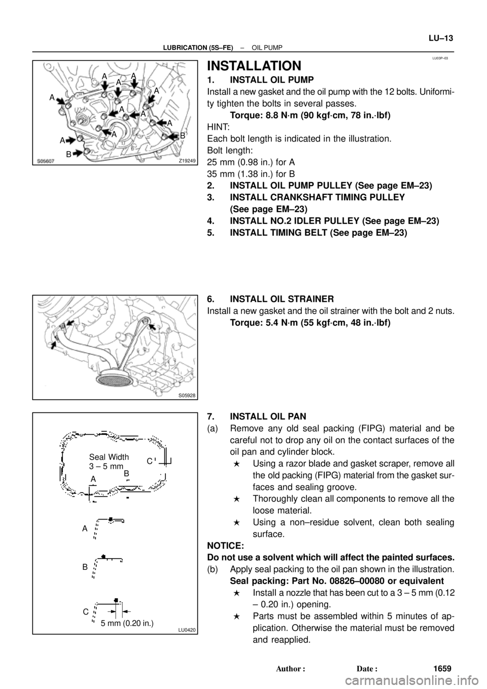
1. INSTALL OIL PUMP
Install a new gasket and the oil pump with the 12 bolts. Uniformi-
ty tighten the bolts in several passes.
Torque: 8.8 N´m (90 kgf´cm, 78 in.´lbf)
HINT:
Each bolt length is indicated in the illustration.
Bolt length:
25 mm (0.98 in.) for A
35 mm (1.38 in.) for B
2. INSTALL OIL PUMP PULLEY (See page EM±23)
3. INSTALL CRANKSHAFT TIMING PULLEY
(See page EM±23)
4. INSTALL NO.2 IDLER PULLEY (See page EM±23)
5. INSTALL TIMING BELT (See page EM±23)
6. INSTALL OIL STRAINER
Install a new gasket and the oil strainer with the bolt and 2 nuts.
Torque: 5.4 N´m (55 kgf´cm, 48 in.´lbf)
7. INSTALL OIL PAN
(a) Remove any old seal packing (FIPG) material and be
careful not to drop any oil on the contact surfaces of the
oil pan and cylinder block.
�Using a razor blade and gasket scraper, remove all
the old packing (FIPG) material from the gasket sur-
faces and sealing groove.
�Thoroughly clean all components to remove all the
loose material.
�Using a non±residue solvent, clean both sealing
surface.
NOTICE:
Do not use a solvent which will affect the painted surfaces.
(b) Apply seal packing to the oil pan shown in the illustration.
Seal packing: Part No. 08826±00080 or equivalent
�Install a nozzle that has been cut to a 3 ± 5 mm (0.12
± 0.20 in.) opening.
�Parts must be assembled within 5 minutes of ap-
plication. Otherwise the material must be removed
and reapplied.
Page 2920 of 4592

LU02D±03
P12969
A
Seal Width
2 ± 3 mmB
A
BC
C
P18779
New O±Ring
± LUBRICATION (1MZ±FE)OIL PUMP
LU±15
1679 Author�: Date�:
INSTALLATION
1. INSTALL OIL PUMP
(a) Remove any old packing (FIPG) material and be careful
not to drop any oil on the contact surfaces of the oil pump
and cylinder block.
�Using a razor blade and gasket scraper, remove all
the old packing (FIPG) material from the gasket sur-
faces and sealing grooves.
�Thoroughly clean all components to remove all the
loose material.
�Using a non±residue solvent, clean both sealing
surfaces.
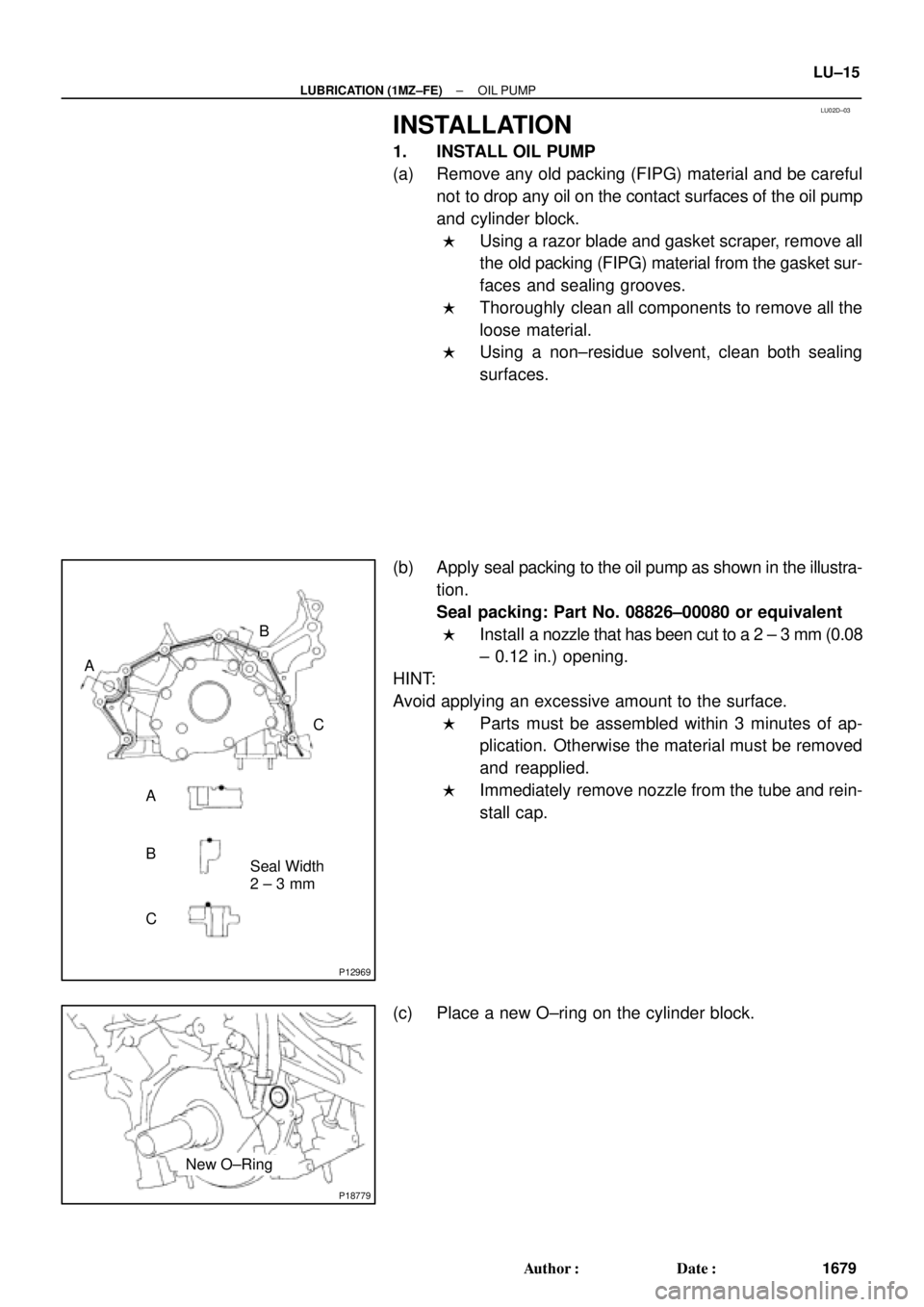
(b) Apply seal packing to the oil pump as shown in the illustra-
tion.
Seal packing: Part No. 08826±00080 or equivalent
�Install a nozzle that has been cut to a 2 ± 3 mm (0.08
± 0.12 in.) opening.
HINT:
Avoid applying an excessive amount to the surface.
�Parts must be assembled within 3 minutes of ap-
plication. Otherwise the material must be removed
and reapplied.
�Immediately remove nozzle from the tube and rein-
stall cap.
(c) Place a new O±ring on the cylinder block.
Page 2922 of 4592

B04402
A Region ºXºRegion ºYº
A
CB B
C
Seal Width
Type A: 4 ± 5 mm
Type B: 3 ± 4 mmRegion ºXºRegion ºYº
AC Type A
Type B
± LUBRICATION (1MZ±FE)OIL PUMP
LU±17
1681 Author�: Date�:
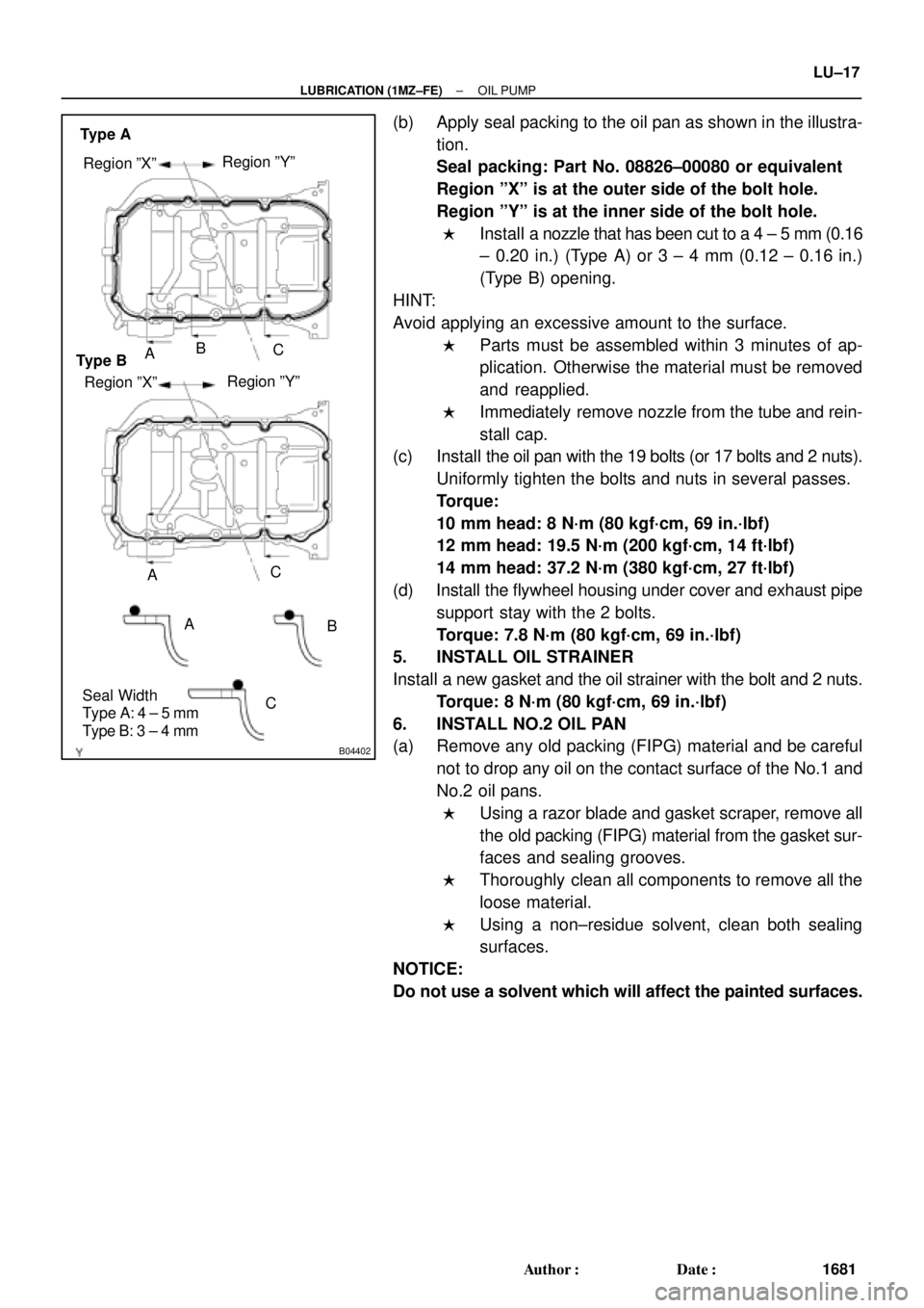
(b) Apply seal packing to the oil pan as shown in the illustra-
tion.
Seal packing: Part No. 08826±00080 or equivalent
Region ºXº is at the outer side of the bolt hole.
Region ºYº is at the inner side of the bolt hole.
�Install a nozzle that has been cut to a 4 ± 5 mm (0.16
± 0.20 in.) (Type A) or 3 ± 4 mm (0.12 ± 0.16 in.)
(Type B) opening.
HINT:
Avoid applying an excessive amount to the surface.
�Parts must be assembled within 3 minutes of ap-
plication. Otherwise the material must be removed
and reapplied.
�Immediately remove nozzle from the tube and rein-
stall cap.
(c) Install the oil pan with the 19 bolts (or 17 bolts and 2 nuts).
Uniformly tighten the bolts and nuts in several passes.
Torque:
10 mm head: 8 N´m (80 kgf´cm, 69 in.´lbf)
12 mm head: 19.5 N´m (200 kgf´cm, 14 ft´lbf)
14 mm head: 37.2 N´m (380 kgf´cm, 27 ft´lbf)
(d) Install the flywheel housing under cover and exhaust pipe
support stay with the 2 bolts.
Torque: 7.8 N´m (80 kgf´cm, 69 in.´lbf)
5. INSTALL OIL STRAINER
Install a new gasket and the oil strainer with the bolt and 2 nuts.
Torque: 8 N´m (80 kgf´cm, 69 in.´lbf)
6. INSTALL NO.2 OIL PAN
(a) Remove any old packing (FIPG) material and be careful
not to drop any oil on the contact surface of the No.1 and
No.2 oil pans.
�Using a razor blade and gasket scraper, remove all
the old packing (FIPG) material from the gasket sur-
faces and sealing grooves.
�Thoroughly clean all components to remove all the
loose material.
�Using a non±residue solvent, clean both sealing
surfaces.
NOTICE:
Do not use a solvent which will affect the painted surfaces.
Page 2923 of 4592

P12568
A
A
BB
Seal Width
4 ± 5 mm LU±18
± LUBRICATION (1MZ±FE)OIL PUMP
1682 Author�: Date�:
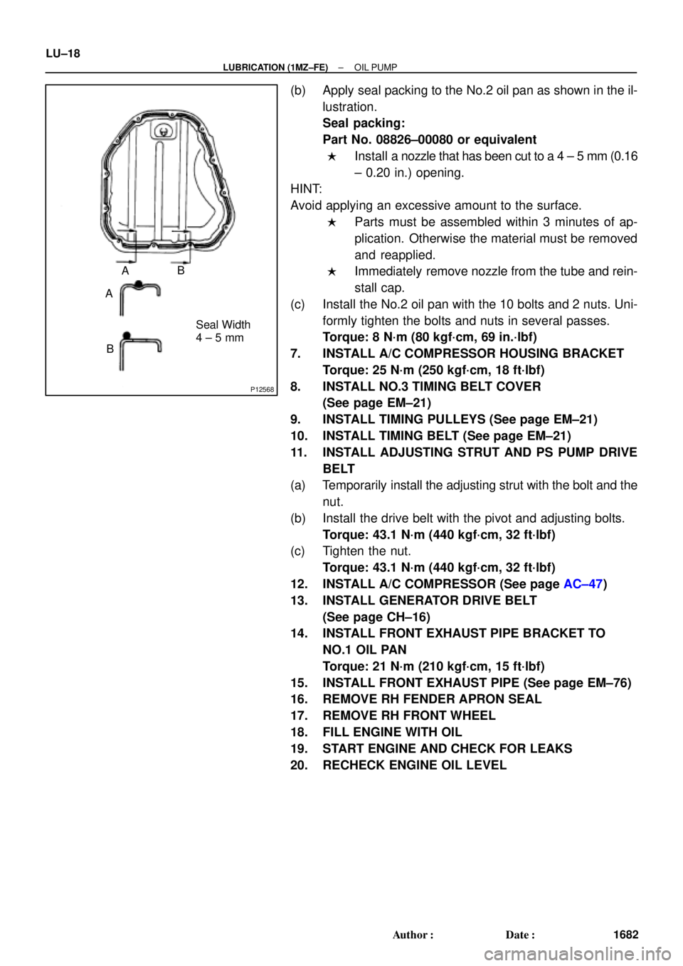
(b) Apply seal packing to the No.2 oil pan as shown in the il-
lustration.
Seal packing:
Part No. 08826±00080 or equivalent
�Install a nozzle that has been cut to a 4 ± 5 mm (0.16
± 0.20 in.) opening.
HINT:
Avoid applying an excessive amount to the surface.
�Parts must be assembled within 3 minutes of ap-
plication. Otherwise the material must be removed
and reapplied.
�Immediately remove nozzle from the tube and rein-
stall cap.
(c) Install the No.2 oil pan with the 10 bolts and 2 nuts. Uni-
formly tighten the bolts and nuts in several passes.
Torque: 8 N´m (80 kgf´cm, 69 in.´lbf)
7. INSTALL A/C COMPRESSOR HOUSING BRACKET
Torque: 25 N´m (250 kgf´cm, 18 ft´lbf)
8. INSTALL NO.3 TIMING BELT COVER
(See page EM±21)
9. INSTALL TIMING PULLEYS (See page EM±21)
10. INSTALL TIMING BELT (See page EM±21)
11. INSTALL ADJUSTING STRUT AND PS PUMP DRIVE
BELT
(a) Temporarily install the adjusting strut with the bolt and the
nut.
(b) Install the drive belt with the pivot and adjusting bolts.
Torque: 43.1 N´m (440 kgf´cm, 32 ft´lbf)
(c) Tighten the nut.
Torque: 43.1 N´m (440 kgf´cm, 32 ft´lbf)
12. INSTALL A/C COMPRESSOR (See page AC±47)
13. INSTALL GENERATOR DRIVE BELT
(See page CH±16)
14. INSTALL FRONT EXHAUST PIPE BRACKET TO
NO.1 OIL PAN
Torque: 21 N´m (210 kgf´cm, 15 ft´lbf)
15. INSTALL FRONT EXHAUST PIPE (See page EM±76)
16. REMOVE RH FENDER APRON SEAL
17. REMOVE RH FRONT WHEEL
18. FILL ENGINE WITH OIL
19. START ENGINE AND CHECK FOR LEAKS
20. RECHECK ENGINE OIL LEVEL
Page 3125 of 4592
PP0MS±01
PP±100
± PREPARATIONSUPPLEMENTAL RESTRAINT SYSTEM
152 Author�: Date�:
EQUIPMENT
Torque wrench
Bolt: Length: 35 mm (1.38 in.) Pitch: 1.0 mm (0.039 in.)
Diam.: 6.0 mm (0.236 in.)Airbag disposal
Tire Width: 185 mm (7.28 in.) Inner diam.: 360mm (14.17 in.)Airbag disposal
Tire with disc wheel Width: 185 mm (7.28 in.)
Inner diam.: 360 mm (14.17 in.)Airbag disposal
Vinyl bagAirbag disposal
Page 3130 of 4592
PP0MV±01
± PREPARATIONBODY
PP±105
157 Author�: Date�:
EQUIPMENT
Clip remover
Torque wrench
Drill
Drill bit, diam 3.2 mm (0.126 in.)
Hand riveter
TapeTo avoid surface damage
Adhesive tapeTo avoid surface damage
Adhesive
Cleaner
Shop ragRegulator handle
Water pump pliersWindow regulator
KnifeMoulding
Heat lightMoulding
Piano wireWindshield
Rope (no projections, difficult to break)Seat belt pretensioner disposal
Tire Width: 185 mm (7.28 in.)
Inner diam: 360 mm (14.17 in.)Seatbelt pretensioner disposal
Tire with disc wheel Width: 185 mm (7.28 in.)
Inner diam 360 mm (14.17 in.)Seat belt pretinsioner disposal
Vinyl bagSeat belt pretensioner disposal