Page 3558 of 4592
 Check the tires for wear and proper inflation pressu")
R03031
SA078±01
R15157
Front
R07928
SA±2
± SUSPENSION AND AXLETIRE AND WHEEL
1953 Author�: Date�:
TIRE AND WHEEL
INSPECTION
1. INSPECT TIRE
(a) Check the tires for wear and proper inflation pressure.
Cold inflation pressure:
Normal driving
Tire sizeFront, Rear
kPa (kgf/cm2 or bar, psi)
P195/70R14 90S, 90H210 (2.1, 30)
P205/65R15 92H*1 220 (2.2, 32)
*2 200 (2.0, 29)
*1: For all loads including full rated loads
*
2: For reduced loads (1 to 4 passengers)
Trailer towing
Tire sizeFront, Rear
kPa (kgf/cm2 or bar, psi)
P195/70R14 90S*1 210 (2.1, 30)
*2 240 (2.4, 36)
P205/65R15 92H*1 220 (2.2, 32)
*2 240 (2.4, 36)
*1: For driving under 160 km/h (100 mph)
*
2: For driving at 160 km/h (100 mph) or over
(b) Check the tire runout.
Tire runout: 1.0 mm (0.039 in.) or less
2. ROTATING TIRES
HINT:
See the illustration for where to rotate each tire.
3. INSPECT WHEEL BALANCE
(a) Check and adjust the Off±the±car balance.
(b) If necessary, check and adjust the On±the±car balance.
Imbalance after adjustment:
8.0 g (0.018 lb) or less
Page 3560 of 4592

W03085
Front
R03030
Rear
SA079±01
Z03382
SA3213
AB
C D
Front SA±4
± SUSPENSION AND AXLEFRONT WHEEL ALIGNMENT
1955 Author�: Date�:
FRONT WHEEL ALIGNMENT
INSPECTION
1. MEASURE VEHICLE HEIGHT
Tire sizeFront*1 mm (in.)Rear*2 mm (in.)
195/70R14212 (8.35)264 (10.39)
205/65R15215 (8.46)266 (10.49)
*1: Front measuring point
Measure from the ground to the center of the front side lower
suspension arm mounting bolt.
*
2: Rear measuring point
Measure from the ground to the center of the strut rod mounting
bolt.
NOTICE:
Before inspecting the wheel alignment, adjust the vehicle
height to the specification.
If the vehicle height is not within the specification, try to adjust
it by pushing down on or lifting the body.
2. INSTALL CAMBER±CASTER±KINGPIN GAUGE
ONTO VEHICLE OR POSITION VEHICLE ON WHEEL
ALIGNMENT TESTER
Follow the specific instructions of the equipment manufacturer.
3. INSPECT CAMBER, CASTER AND STEERING AXIS
INCLINATION
5S±FE1MZ±FE
Camber
Left±right error±0°36' ± 45'
(±0.6° ± 0.75°)
45' (0.75°) or less±0°37' ± 45'
(±0.62° ± 0.75°)
45' (0.75°) or less
Caster
Left±right error2°10' ± 45'
(2.17° ± 0.75°)
45' (0.75°) or less2°11' ± 45'
(2.18° ± 0.75°)
45' (0.75°) or less
Steering axis inclination
Left±right error13°01' ± 45'
(13.02° ± 0.75°)
45' (0.75°) or less13°04' ± 45'
(13.07° ± 0.75°)
45' (0.75°) or less
HINT:
If the caster and steering axis inclination are not within the spec-
ification, after the camber has correctly adjusted, recheck the
suspension parts for damaged and/or worn out parts.
4. INSPECT TOE±IN
Toe±in
(Total)A + B: 0° ± 12' (0° ± 0.2°)
C ± D: 0 ± 2 mm (0 ± 0.08 in.)
If the toe±in is not within the specification, adjust it at the rack
ends.
Page 3562 of 4592
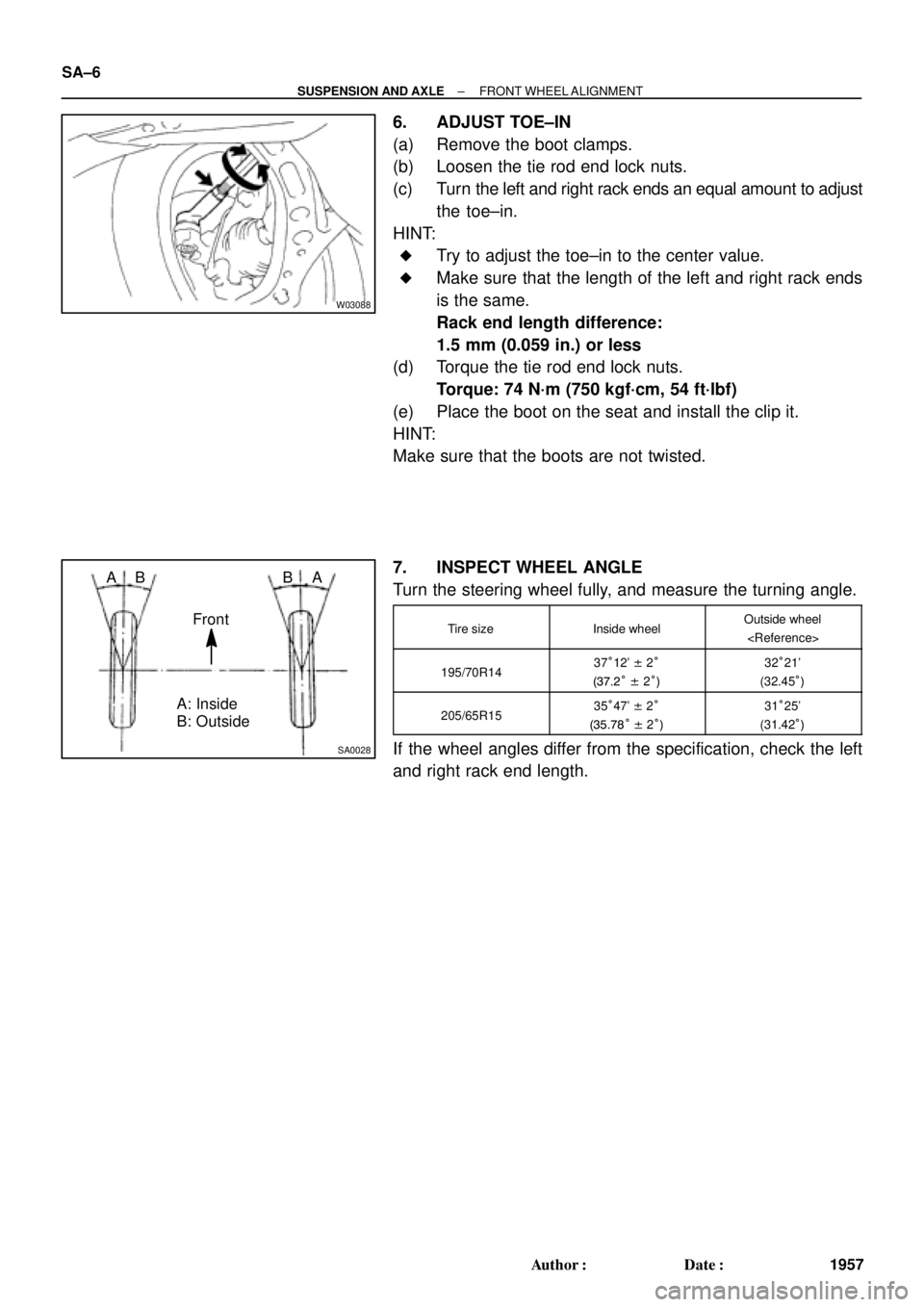
W03088
SA0028
A: Inside
B: Outside AB
Front BA SA±6
± SUSPENSION AND AXLEFRONT WHEEL ALIGNMENT
1957 Author�: Date�:
6. ADJUST TOE±IN
(a) Remove the boot clamps.
(b) Loosen the tie rod end lock nuts.
(c) Turn the left and right rack ends an equal amount to adjust
the toe±in.
HINT:
�Try to adjust the toe±in to the center value.
�Make sure that the length of the left and right rack ends
is the same.
Rack end length difference:
1.5 mm (0.059 in.) or less
(d) Torque the tie rod end lock nuts.
Torque: 74 N´m (750 kgf´cm, 54 ft´lbf)
(e) Place the boot on the seat and install the clip it.
HINT:
Make sure that the boots are not twisted.
7. INSPECT WHEEL ANGLE
Turn the steering wheel fully, and measure the turning angle.
Tire sizeInside wheelOutside wheel
195/70R1437°12' ± 2°
(37.2° ± 2°)32°21'
(32.45°)
205/65R1535°47' ± 2°
(35.78° ± 2°)31°25'
(31.42°)
If the wheel angles differ from the specification, check the left
and right rack end length.
Page 3629 of 4592

F08080
Front:
Rear:SA1DP±03
Z03382
± SUSPENSION AND AXLEFRONT WHEEL ALIGNMENT
SA±1
508 Author�: Date�:
FRONT WHEEL ALIGNMENT
INSPECTION
1. MEASURE VEHICLE HEIGHT
Vehicle height:
Tire sizeFront*1 mm (in.)Rear*2 mm (in.)
205/65R15218 (8.58)270 (10.63)
*1: Front measuring point
Measure the distance from the ground to the center of the front
side lower suspension arm mounting bolt.
*
2: Rear measuring point
Measure the distance from the ground to the center of the front
side strut rod mounting bolt.
NOTICE:
Before inspecting the wheel alignment, adjust the vehicle
height to the specified value.
If the vehicle height is not the specified value, try to adjust it by
pushing down on or lifting the body.
2. INSTALL CAMBER±CASTER±KINGPIN GAUGE OR
POSITION VEHICLE ON WHEEL ALIGNMENT TES-
TER
Follow the specific instructions of the equipment manufacturer.
3. INSPECT CAMBER, CASTER AND STEERING AXIS
INCLINATION
Camber, caster and steering axis inclination:
Camber
Right±left error±0°36' ± 45' (±0.6° ± 0.75°)
45' (0.75°) or less
Caster
Right±left error2°10' ± 45' (2.17° ± 0.75°)
45' (0.75°) or less
Steering axis inclination
Right±left error13°01' ± 45' (13.02° ± 0.75°)
45' (0.75°) or less
If the caster and steering axis inclination are not within the spe-
cified values, after the camber has been correctly adjusted, re-
check the suspension parts for damaged and/or worn out parts.
4. ADJUST CAMBER
NOTICE:
After the camber has been adjusted, inspect the toe±in.
(a) Remove the front wheel and ABS speed sensor clamp.