Page 311 of 4592
AUTOMATIC TRANSAXLEOPERATION ±
AX±5
3. HYDRAULIC CONTROL SYSTEM
The hydraulic control system is composed of the oil pump, the valve body, the solenoid valves, the accu-
mulators, the clutches and brakes as well as the fluid passages which connect all of these components.
Based on the hydraulic pressure created by the oil pump, the hydraulic control system governs the hy-
draulic pressure acting on the torque converter clutch, clutches and brakes in accordance with the ve-
hicle driving conditions.
There are three solenoid valves on the valve body.
The No.1 and No.2 solenoid vales are turned on and off by signals from the ECM to operate the shift
valves and change the gear shift position.
The SL solenoid valve is operated by signals from the ECM to engage or disengage the lock±up clutch
of the torque converter clutch.
The SLN solenoid valve is operated by signals from the ECM to control the engagement speed and
reduce gear shift shock.
AX01A±0B
Page 385 of 4592
AUTOMATIC TRANSAXLEVALVE BODY ±
AX±79
7. REMOVE OIL STRAINER, NO.1 LOWER VALVE BODY
COVER GASKETS AND CHECK VALVE
(a) Remove the 2 gaskets and plate from the lower valve
body.
(b) Remove the oil strainer, check valve and spring.
8. REMOVE PRESSURE RELIEF VALVE
9. REMOVE NO.2 LOWER VALVE BODY COVER, OIL
STRAINER, CHECK BALLS AND VIBRATING STOP-
PER
Remove the 11 bolts and lower valve body cover.
(b) Remove the 2 check balls, oil strainer and vibrating stop-
per.
Page 390 of 4592
AUTOMATIC TRANSAXLEVALVE BODY ±
AX±84
10. INSTALL LOWER VALVE BODY COVER GASKETS
AND NO.2 PLATE
Position a new gasket and plate and then another new
gasket.
HINT: Both gaskets are identical.
11. INSTALL LOWER VALVE BODY COVER
(a) Position the lower valve body cover.
(b) Install and finger tighten the 5 bolts.
HINT: Each bolt length is indicated below.
Bolt length
Bolt A: 47 mm (1.850 in.)
Bolt B: 14 mm (0.551 in.)
12. INSTALL PRESSURE RELIEF VALVE
13. TIGHTEN BOLTS OF UPPER AND LOWER VALVE BO-
DIES
(a) Tighten the 16 bolts in the lower valve body.
Torque: 6.6 N´m (67 kgf´cm, 58 in.´lbf)
(b) Tighten the 3 bolts in the upper valve body.
Torque: 6.6 N´m (67 kgf´cm, 58 in.´lbf)
14. INSTALL B0 ACCUMULATOR ASSEMBLY
(a) Coat new O±rings with ATF and install them to the piston.
(b) Install the spring and piston into the cylinder.
Spring dimensions
mm (in.)
ColorFree lengthCoil outer diameter
Inner White47.5 (1.870)18.9 (0.744)
Outer None16.3 (0.642)20.7 (0.815)
Page 454 of 4592
AUTOMATIC TRANSAXLEOPERATION ±
AX±5
3. HYDRAULIC CONTROL SYSTEM
The hydraulic control system is composed of the oil pump, the valve body, the solenoid valves, the accu-
mulators, the clutches and brakes as well as the fluid passages which connect all of these components.
Based on the hydraulic pressure created by the oil pump, the hydraulic control system governs the hy-
draulic pressure acting on the torque converter clutch, clutches and brakes in accordance with the ve-
hicle driving conditions.
There are three solenoid valves on the valve body.
The No.1 and No.2 solenoid vales are turned on and off by signals from the ECM to operate the shift
valves and change the gear shift position.
The SL solenoid valve is operated by signals from the ECM to engage or disengage the lock±up clutch
of the torque converter clutch.
The SLN solenoid valve is operated by signals from the ECM to control the engagement speed and
reduce gear shift shock.
AX01A±0B
Page 528 of 4592
AUTOMATIC TRANSAXLEVALVE BODY ±
AX±79
7. REMOVE OIL STRAINER, NO.1 LOWER VALVE BODY
COVER GASKETS AND CHECK VALVE
(a) Remove the 2 gaskets and plate from the lower valve
body.
(b) Remove the oil strainer, check valve and spring.
8. REMOVE PRESSURE RELIEF VALVE
9. REMOVE NO.2 LOWER VALVE BODY COVER, OIL
STRAINER, CHECK BALLS AND VIBRATING STOP-
PER
Remove the 11 bolts and lower valve body cover.
(b) Remove the 2 check balls, oil strainer and vibrating stop-
per.
Page 533 of 4592
AUTOMATIC TRANSAXLEVALVE BODY ±
AX±84
10. INSTALL LOWER VALVE BODY COVER GASKETS
AND NO.2 PLATE
Position a new gasket and plate and then another new
gasket.
HINT: Both gaskets are identical.
11. INSTALL LOWER VALVE BODY COVER
(a) Position the lower valve body cover.
(b) Install and finger tighten the 5 bolts.
HINT: Each bolt length is indicated below.
Bolt length
Bolt A: 47 mm (1.850 in.)
Bolt B: 14 mm (0.551 in.)
12. INSTALL PRESSURE RELIEF VALVE
13. TIGHTEN BOLTS OF UPPER AND LOWER VALVE BO-
DIES
(a) Tighten the 16 bolts in the lower valve body.
Torque: 6.6 N´m (67 kgf´cm, 58 in.´lbf)
(b) Tighten the 3 bolts in the upper valve body.
Torque: 6.6 N´m (67 kgf´cm, 58 in.´lbf)
14. INSTALL B0 ACCUMULATOR ASSEMBLY
(a) Coat new O±rings with ATF and install them to the piston.
(b) Install the spring and piston into the cylinder.
Spring dimensions
mm (in.)
ColorFree lengthCoil outer diameter
Inner White47.5 (1.870)18.9 (0.744)
Outer None16.3 (0.642)20.7 (0.815)
Page 587 of 4592

BE±6
± BODY ELECTRICALBODY ELECTRICAL SYSTEM
2226 Author�: Date�:
Washer fluid does not operate.1. Washer Hose and Nozzle±
� In wiper switch HI position, the wiper blade is in contact with
the body.
� When the wiper switch is OFF, the wiper blade does not
retract or the retract position is wrong.1. *1Wiper Switch
2. Wire HarnessBE±40
±
COMBINATION METER
METER, GAUGES AND ILLUMINATION:
SymptomSuspect AreaSee page
Tachometer, Fuel Gauge and Engine Coolant Temperature Gauge
do not operate.1. GAUGE Fuse (I/P J/B No.1)
2. Meter Circuit Plate
3. Wire Harness±
BE±46
±
Speedometer does not operate.
1. No.1 Vehicle Speed Sensor
2. Meter Circuit Plate
3. Wire HarnessBE±47
BE±46
±
Tachometer does not operate.
1. Igniter (5S±FE)
(1MZ±FE)
2. Meter Circuit Plate
3. Wire HarnessIG±1
IG±1
BE±46
±
Fuel Gauge does not operate or abnormal operation.
1. Fuel Receiver Gauge
2. Fuel Sender Gauge
3. Meter Circuit Plate
4. Wire HarnessBE±47
BE±47
BE±46
±
Engine Coolant Temperature Gauge does not operate or abnormal
operation
1. Engine Coolant Temperature Receiver Gauge
2. Engine Coolant Temperature Sender Gauge
3. Meter Circuit Plate
4. Wire HarnessBE±47
BE±47
BE±46
±
All illumination lights do not light up.
1. TAIL Fuse (I/P J/B No.1)
2. Light Control Rheostat
3. Wire Harness±
BE±47
±
Brightness does not change even when rheostat turned.1. Bulb
2. Wire Harness±
±
Only one illumination light does not light up.1. Bulb
2. Wire Harness±
±
COMBINATION METER
WARNING LIGHTS:
SymptomSuspect AreaSee page
Warning lights do not light up. (Except Discharge, Open Door and
SRS)1. GAUGE Fuse (I/P J/B No.1)
2. Meter Circuit Plate
3. Wire Harness±
BE±46
±
Low Oil Pressure warning light does not light up.
1. Bulb
2. Low Oil Pressure Warning Switch
3. Meter Circuit Plate
4. Wire Harness±
BE±47
BE±46
±
Fuel Level warning light does not light up.
1. Bulb
2. Fuel Level Warning Switch
3. Meter Circuit Plate
4. Wire Harness±
BE±47
BE±46
±
ABS warning light does not light up.
1. Bulb
2. ABS ECU
3. Wire Harness±
IN±31
±
Page 626 of 4592
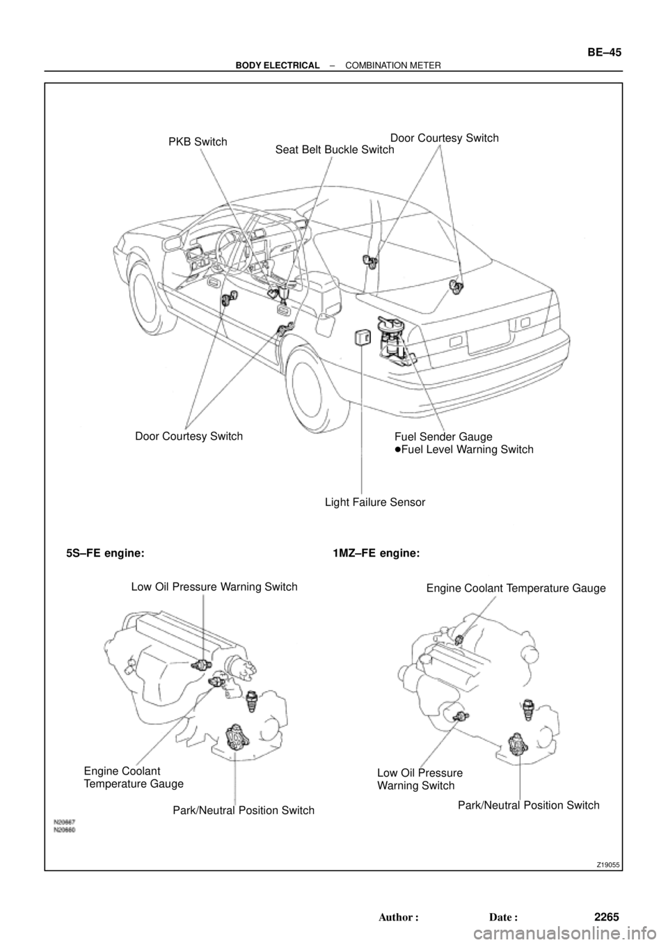
Z19055
PKB Switch
Seat Belt Buckle SwitchDoor Courtesy Switch
Door Courtesy Switch
Light Failure SensorFuel Sender Gauge
�Fuel Level Warning Switch
5S±FE engine: 1MZ±FE engine:
Low Oil Pressure Warning Switch
Engine Coolant Temperature Gauge
Engine Coolant
Temperature Gauge
Park/Neutral Position SwitchLow Oil Pressure
Warning Switch
Park/Neutral Position Switch
± BODY ELECTRICALCOMBINATION METER
BE±45
2265 Author�: Date�:

 Remove the 2 gaskets and plate from the lower valve
body.
(b) Remove the oil str")


 Remove the 2 gaskets and plate from the lower valve
body.
(b) Remove the oil str")