Page 1755 of 4592
DI03X±05
F01175
ABS Actuator
(w/ ECU, Relay)Front Speed Sensor
DLC1
DLC2Sensor Rotor
Rear Speed Sensor
Stop Light Switch ABS Warning Light
Sensor Rotor
Front Speed Sensor
± DIAGNOSTICSANTI±LOCK BRAKE SYSTEM (BOSCH Made)
DI±543
778 Author�: Date�:
PARTS LOCATION
Page 1756 of 4592

779 Author�: Date�:
TERMINALS OF ECU
Symbols (Terminals No.)Wiri")
DI1JN±03
F00050
A6
12 345678
910 1112 13 14 15
16 17 181920 21 2223 24 2526 DI±544
± DIAGNOSTICSANTI±LOCK BRAKE SYSTEM (BOSCH Made)
779 Author�: Date�:
TERMINALS OF ECU
Symbols (Terminals No.)Wiring ColorConditionSTD Voltage (V)
+B (A6 ± 17, 18) ± GND (A6 ±
16, 19)L e W±BAlways10 ± 14
IG1 (A6 ± 15) ± GND (A6 ± 16,
19)B±R e W±BIG switch ON10 ± 14
WA (A6 ± 21) ± GND (A6 ± 16,RLWBIG switch ON, ABS warning light ONBelow 2.6WA (A6 21) GND (A6 16,
26)R±L e W±BIG switch ON, ABS warning light OFF10 ± 14
STP (A6 ± 14) ± GND (A6 ± 16,GWWBStop light switch OFFBelow 1.5STP (A6 14) GND (A6 16,
19)G±W e W±BStop light switch ON5 ± 14
Tc (A6 ± 12) ± GND (A6 ± 16,
19)LG±R e W±BIG switch ON5.7 ± 8.1
Ts (A6 ± 11) ± GND (A6 ± 16,
19)R±Y e W±BIG switch ON5.7 ± 8.1
FR+ (A6 ± 5) ± FR± (A6 ± 4)W e BIG switch ON, slowly turn right front wheelAC generation
FL+ (A6 ± 7) ± FL± (A6 ± 6)R e GIG switch ON, slowly turn left front wheelAC generation
RR+ (A6 ± 3) ± RR± (A6 ± 1)P e LIG switch ON, slowly turn right rear wheelAC generation
RL+ (A6 ± 9) RL± (A6 ± 8)Y e BRIG switch ON, slowly turn left rear wheelAC generation
Page 1757 of 4592

DI±545
780 Author�: Date�:
PROBLEM SYMPTOMS TABLE
If a normal code is displayed during the DTC check but the problem still occurs, check t")
DI03Z±10
± DIAGNOSTICSANTI±LOCK BRAKE SYSTEM (BOSCH Made)
DI±545
780 Author�: Date�:
PROBLEM SYMPTOMS TABLE
If a normal code is displayed during the DTC check but the problem still occurs, check the circuits for each
problem symptom in the order given in the table below and proceed to the relevant troubleshooting page.
SymptomSuspect AreaSee page
ABS does not operate
Only when 1. to 4. are all normal and the problem is still
occurring, replace the ABS ECU.
1. Check the DTC reconfirming that the normal code is
output.
2. Power source circuit
3. Speed sensor circuit
4. Check the hydraulic circuit for leakage.
DI±539
DI±558
DI±552
DI±571
ABS does not operate intermittently
Only when 1. to 4. are all normal and the problem is still
occurring, replace the ABS ECU.
1. Check the DTC reconfirming that the normal code is
output.
2. Speed sensor circuit
3. Stop light switch circuit
4. Check the hydraulic circuit for leakage.
DI±539
DI±552
DI±561
DI±571
ABS warning light abnormal1. ABS warning light circuit
2. ABS ECUDI±565
DI±563
DTC check cannot be done
Only when 1. and 2. are all normal and the problem is still
occurring, replace the ABS ECU.
1. ABS warning light circuit
2. Tc terminal circuit
DI±565
DI±567
Speed sensor signal check cannot be done1. Ts terminal circuit
2. ABS ECUDI±569
DI±563
Page 1758 of 4592

DI040±08
F03949
Actuator Assembly
BatteryActuator Assembly
MAINB±GF4 1 ALT
FL
Block 1F5 B±G3
ABS
12 3
Engine
Room R/B
No.3L
L
18
A6
+B+BA6
Valve Relay
Motor Relay17
A6 16 GND2
W±BEA
W±B
W±B 19
A6GND1 ECU DI±546
± DIAGNOSTICSANTI±LOCK BRAKE SYSTEM (BOSCH Made)
781 Author�: Date�:
CIRCUIT INSPECTION
DTC 11 ABS Solenoid Valve Relay Circuit
CIRCUIT DESCRIPTION
This relay supplies power to each ABS solenoid. After the ignition switch is turned ON, if the initial check is
OK, the relay goes on.
DTC No.DTC Detecting ConditionTrouble Area
11
Detection of any conditions from 1. through 3.:
1. 3 or more solenoid valves are shown faulty in response
and simultaneously valve supply voltage is detected
faulty.
2. Solenoid valve relay will not be switched OFF.
3. Valve relay is frozen in spite of its high valve relay sup-
ply voltage.
�ABS solenoid valve relay
�Valve supply voltage
�ECU
Fail safe function:
If trouble occurs in the ABS solenoid valve relay circuit, the ECU cuts off current to the ABS solenoid valve
relay and prohibits ABS control.
WIRING DIAGRAM
Page 1759 of 4592
F00064
LOCK
191817
16
(+) (±) LOCK
191817
16
(+) (±)
A6 LOCK
191817
16
(+) (±)
± DIAGNOSTICSANTI±LOCK BRAKE SYSTEM (BOSCH Made)
DI±547
782 Author�: Date�:
INSPECTION PROCEDURE
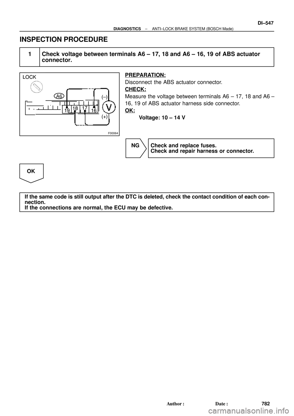
1 Check voltage between terminals A6 ± 17, 18 and A6 ± 16, 19 of ABS actuator
connector.
PREPARATION:
Disconnect the ABS actuator connector.
CHECK:
Measure the voltage between terminals A6 ± 17, 18 and A6 ±
16, 19 of ABS actuator harness side connector.
OK:
Voltage: 10 ± 14 V
NG Check and replace fuses.
Check and repair harness or connector.
OK
If the same code is still output after the DTC is deleted, check the contact condition of each con-
nection.
If the connections are normal, the ECU may be defective.
Page 1760 of 4592

F03949
Actuator Assembly
BatteryActuator Assembly
MAINB±GF4 1 ALT
FL
Block 1F5 B±G3
ABS
12 3L
L
18
A6
+B+BA6
Valve Relay
Motor Relay17
A6 16 GND2
W±BEA
W±B
W±B 19
A6GND1 ECU Engine
Room R/B
No.3 DI±548
± DIAGNOSTICSANTI±LOCK BRAKE SYSTEM (BOSCH Made)
783 Author�: Date�:
DTC 13 Pump Motor Circuit
CIRCUIT DESCRIPTION
The ABS motor relay supplies power to the ABS pump motor. While the ABS is activated, the ECU switches
the ABS motor relay ON and operates the ABS pump motor.
DTC No.DTC Detecting ConditionTrouble Area
13
Detection of any conditions from (1) through (3):
1. After actuation of the motor relay, pump motor voltage
will not be supplied within 0.4 sec.
2. Pump motor voltage is at a high level, motor relay will
not actuate for 2.5 sec. or more.
3. Pump motor voltage keeps low level for longer than 0.4
sec. and the pump repeats activating for 7 sec. 3 times
maximally. since the last activation, the pump motor has
been gone dead because of short circuit.
�ABS motor relay
�Pump motor voltage
�Pump motor lead disconnected
�ECU
Fail safe function:
If trouble occurs in the ABS motor relay circuit, the ECU cuts off current to the ABS solenoid relay and prohib-
its ABS control.
WIRING DIAGRAM
DI041±08
Page 1761 of 4592
F00064
LOCK
1918 17
16
(+)(±) LOCK
1918 17
16
(+)(±)
A6 LOCK
1918 17
16
(+)(±)
± DIAGNOSTICSANTI±LOCK BRAKE SYSTEM (BOSCH Made)
DI±549
784 Author�: Date�:
INSPECTION PROCEDURE
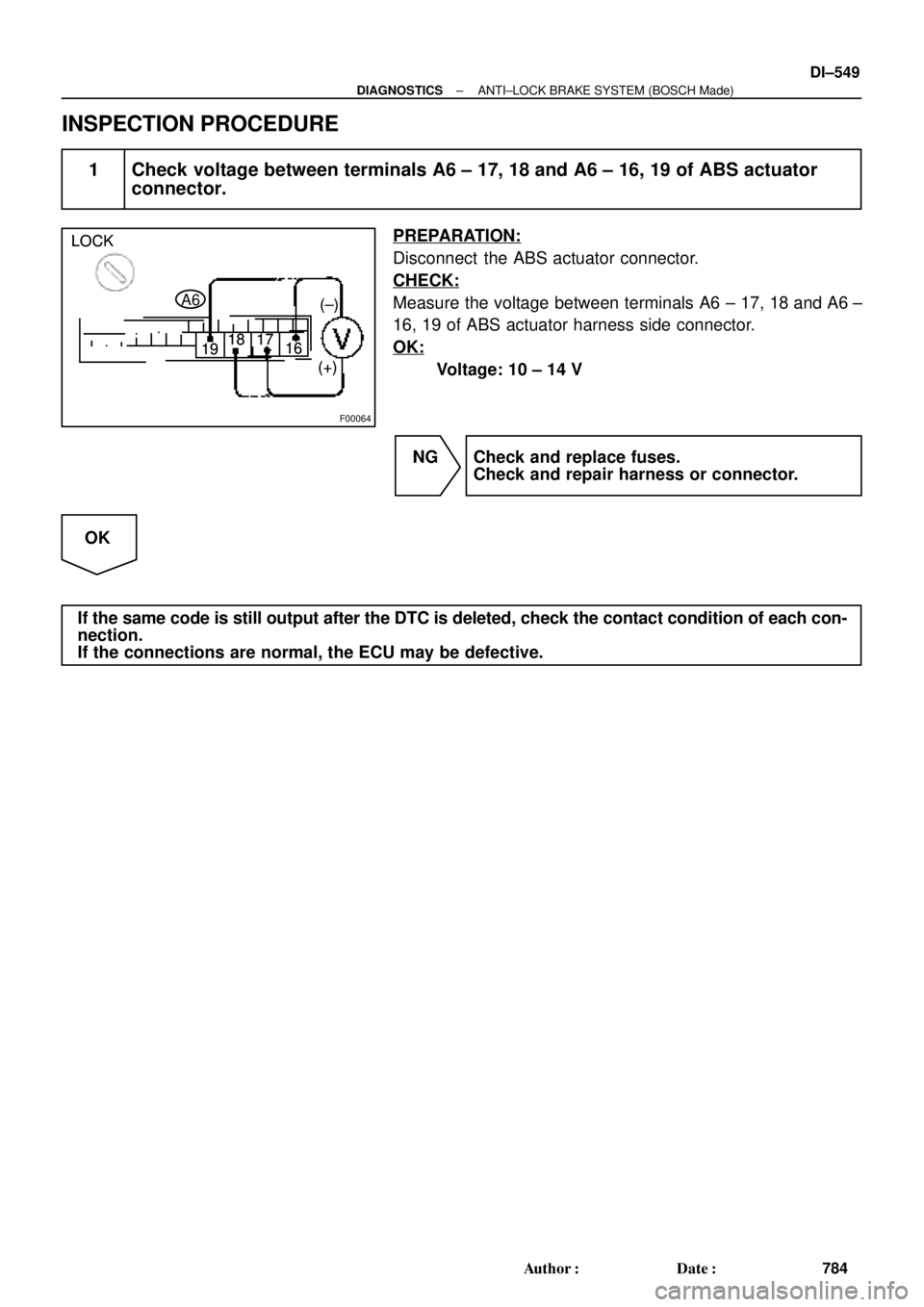
1 Check voltage between terminals A6 ± 17, 18 and A6 ± 16, 19 of ABS actuator
connector.
PREPARATION:
Disconnect the ABS actuator connector.
CHECK:
Measure the voltage between terminals A6 ± 17, 18 and A6 ±
16, 19 of ABS actuator harness side connector.
OK:
Voltage: 10 ± 14 V
NG Check and replace fuses.
Check and repair harness or connector.
OK
If the same code is still output after the DTC is deleted, check the contact condition of each con-
nection.
If the connections are normal, the ECU may be defective.
Page 1762 of 4592
F03949
Actuator Assembly
BatteryActuator Assembly
MAINB±GF4 1 ALT
FL
Block 1F5 B±G3
ABS
12 3
Engine
Room R/B
No.3L
L
18
A6
+B+BA6
Valve Relay
Motor Relay17
A6 16 GND2
W±BEA
W±B
W±B 19
A6GND1 ECU DI±550
± DIAGNOSTICSANTI±LOCK BRAKE SYSTEM (BOSCH Made)
785 Author�: Date�:
DTC 21, 22, 23, 24 ABS Solenoid Valve Circuit
CIRCUIT DESCRIPTION
This solenoid goes on when signals are received from the ECU and controls the pressure acting on the wheel
cylinders thus controlling the braking force.
DTC No.DTC Detecting ConditionTrouble Area
21, 22, 23, 24Solenoid valve signal does not match to the check result.�Each solenoid valve
Fail safe function:
If trouble occurs in the actuator solenoid valve circuit, the ECU cuts off current to the ABS solenoid valve
relay and prohibits ABS control.
WIRING DIAGRAM
DI042±08
Front Speed Sensor
DLC1
DLC2Sensor Rotor
Rear Speed Sensor
Stop Light Switch ABS Warning Light
Sensor Rotor
Front Speed Sensor
± DIAGNOSTICSANTI±LOCK BRA")