Page 3405 of 4592
SF07F±03
B06392
Type A
Rear Seat Cushion
Floor Service Hole Cover
Fuel Pump and Sender
Gauge Connector
No.1 Fuel Tank Protector
Fuel Tank Vent Tube Set Plate
Fuel Pressure
Regulator
Fuel Filter Fuel Pump Assembly
� Gasket
N´m (kgf´cm, ft´lbf)� O±Ring � O±Ring
� Non±reusable part: Specified torque
4 (40,35 in.´lbf)
x 8
± SFI (1MZ±FE)FUEL PRESSURE REGULATOR
SF±17
1516 Author�: Date�:
FUEL PRESSURE REGULATOR
COMPONENTS
Page 3406 of 4592
B06393
Type B
Rear Seat Cushion
Floor Service Hole Cover
Fuel Pump and Sender
Gauge Connector
No.1 Fuel Tank Protector
Fuel Tank Vent Tube Set Plate
Fuel Pressure
Regulator
Fuel Filter Fuel Pump Assembly
� Gasket
N´m (kgf´cm, ft´lbf)� O±Ring � O±Ring
� Non±reusable part: Specified torque
4 (40, 35 in.´lbf)x 8
SF±18
± SFI (1MZ±FE)FUEL PRESSURE REGULATOR
1517 Author�: Date�:
Page 3407 of 4592
SF07G±03
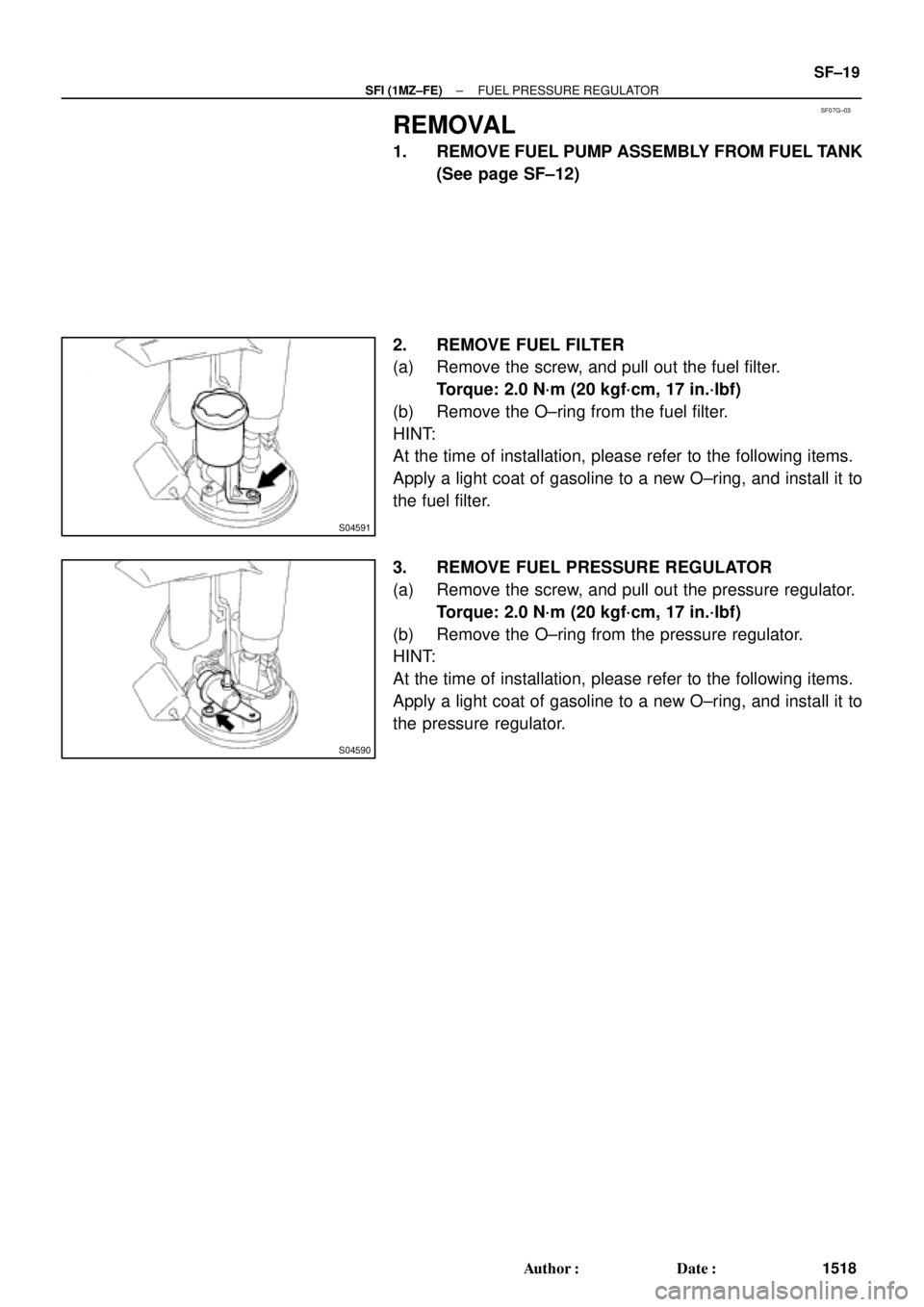
S04591
S04590
± SFI (1MZ±FE)FUEL PRESSURE REGULATOR
SF±19
1518 Author�: Date�:
REMOVAL
1. REMOVE FUEL PUMP ASSEMBLY FROM FUEL TANK
(See page SF±12)
2. REMOVE FUEL FILTER
(a) Remove the screw, and pull out the fuel filter.
Torque: 2.0 N´m (20 kgf´cm, 17 in.´lbf)
(b) Remove the O±ring from the fuel filter.
HINT:
At the time of installation, please refer to the following items.
Apply a light coat of gasoline to a new O±ring, and install it to
the fuel filter.
3. REMOVE FUEL PRESSURE REGULATOR
(a) Remove the screw, and pull out the pressure regulator.
Torque: 2.0 N´m (20 kgf´cm, 17 in.´lbf)
(b) Remove the O±ring from the pressure regulator.
HINT:
At the time of installation, please refer to the following items.
Apply a light coat of gasoline to a new O±ring, and install it to
the pressure regulator.
Page 3414 of 4592
SST (Hose)
O±Ring
SST
(Clamp)
Vinyl Tube
Vinyl Tube
O±Ring
SST (Union)
SST (Hose)
SST
(Clamp)
California A/T
Except California A/T
S05358
TOYOTA
Hand±Held Tester SF±26
± SFI (1M")
B01914
SST (Union)SST (Hose)
O±Ring
SST
(Clamp)
Vinyl Tube
Vinyl Tube
O±Ring
SST (Union)
SST (Hose)
SST
(Clamp)
California A/T
Except California A/T
S05358
TOYOTA
Hand±Held Tester SF±26
± SFI (1MZ±FE)INJECTOR
1525 Author�: Date�:
(c) Install the grommet and O±Ring to the injector.
(d) Connect SST (union and hose) to the injector, and hold
the injector and union with SST (clamp).
SST 09268±41047
(e) Put the injector into a graduated cylinder.
HINT:
Install a suitable vinyl hose onto the injector to prevent gasoline
from splashing out.
(f) Connect a TOYOTA hand±held tester to the DLC3.
(g) Turn the ignition switch ON and push the TOYOTA hand±
held tester main switch ON.
NOTICE:
Do not start the engine.
(h) Select the ACTIVE TEST mode on the TOYOTA hand±
held tester.
(i) Please refer to the TOYOTA hand±held tester operator's
manual for further details.
(j) If you have no TOYOTA hand±held tester, connect the
positive (+) and negative (±) leads from the battery to the
fuel pump connector. (See page SF±6)
Page 3419 of 4592

Before installing the heated oxygen sensor,
twist the sensor wire counterclockwise
3 and 1/2 turns. HINT:
After installing the heated oxygen sen")
SF07N±03
B06469
Heated Oxygen Sensor (Bank 1 Sensor 2)
Before installing the heated oxygen sensor,
twist the sensor wire counterclockwise
3 and 1/2 turns. HINT:
After installing the heated oxygen sensor,
check that the sensor wire is not twisted,
if it is twisted, remove the heated oxygen
sensor and reinstall it. �
Location of Fuel Tank Cushion
No.1 Fuel Tank
Protector
Fuel Tank Vent
Tube Set Plate
Fuel Pump
Fuel Outlet Tube
Fuel Inlet Pipe Fuel Inlet Pipe ShieldFuel Tank Cap
Fuel Inlet Pipe Protector
Heated Oxygen Sensor
(Bank 1 Sensor 2)Heat Insulator
Fuel Tank Band
Center Exhaust Pipe � Gasket� Gasket � Gasket
� Non±reusable part
N´m (kgf´cm, ft´lbf): Specified torque
39 (400, 29)
44 (450, 33)
56 (570, 41)
56 (570, 41)
x 8
�
� Gasket
Fuel TankFuel Inlet Hose
Charcoal
Canister
EVAP Line Hose
Vent Line Hose
± SFI (1MZ±FE)FUEL TANK AND LINE
SF±31
1530 Author�: Date�:
FUEL TANK AND LINE
COMPONENTS
CAUTION:
�Always use new gaskets when replacing the fuel tank or component parts.
�Apply the proper torque to all parts tightened.
Page 3809 of 4592

PRELIMINARY CHECK
� Fuel level should be between
1/4 and 3/4
�V")
EVAP SYSTEM OPERATION INFORMATION ± EG005-01 April 27, 2001
Page 11 of 14
Diagnostic Process Flow Chart
(Continued on following page)
PRELIMINARY CHECK
� Fuel level should be between
1/4 and 3/4
�Visually inspect for presence
of Fuel/Gas Cap
DO NOT TIGHTEN OR REMOVE!
PRESSURIZE EVAP SYSTEM (System Integrity Check)
This test checks for leaks in the canister and fuel tank sides. The CCV and Air Inlet Lines will be checked
separately.
A) Clamp the air drain hose on the charcoal canister with the supplied hose pliers from the EVAP System
Pressure Test Kit.
B) Locate the vapor pressure sensor. If the vapor pressure sensor has two hoses connected to it,
disconnect the hose between the air drain hose fitting at the vapor pressure sensor and plug the hose.
C) Connect the pressure supply hose from the Pressure Test Kit to the Green EVAP System Service Port
located on the EVAP Purge VSV line in the engine compartment.
D) Using the directions on the inside of the EVAP System Pressure Test Kit lid, pressurize the EVAP
system. Once pressurized, turn off the pump and seal the system (Pressure Hold Switch to ªClosedº
and Vent Switch to ªClosed).
E) After 30 seconds, note the pump pressure gauge reading and the Scan Tool vapor pressure
sensor reading.
F) Compare the readings to one of the four conditions listed below and proceed as directed.
DO NOT PROCEED! NG
OK
SCAN TOOL SETUP
A) Connect Scan Tool to DLC3 on vehicle.
B) Go to the SETUP menu and select UNIT CONVERSION.
C) Under VAPOR PRESSURE, Select ABS for absolute pressure, and mmHg for millimeters of mercury.
This is to match the Repair Manual specifications.
D) Go back to FUNCTION SELECT menu and select ENHANCED OBD II.
E) Select NORMAL MODE. Then select CURRENT DATA and USER SELECT.
F) Using the arrow key, select VAPOR PRESS from the DATA LIST and select YES.
G) Press ENTER. You will now be able to monitor the Vapor Pressure Sensor reading.
START
If vehicle is ECHO, go directly to ªECHO Canister and Tank Leak Checkº on page 14.
If vehicle is not ECHO, follow the flow chart below.
Diagnostic
Tips for Late
Type EVAP
System
(Continued)
Page 3810 of 4592
. No leak in
canister or tank.Pump p")
EVAP SYSTEM OPERATION INFORMATION ± EG005-01 April 27, 2001
Page 12 of 14
Pump pressure
gauge and vapor
pressure above
atmospheric
pressure (above 762
mmHg). No leak in
canister or tank.Pump pressure
gauge zero, vapor
pressure above
atmospheric
pressure (above 762
mmHg). Leak is on
canister side of
system.Pump pressure
gauge is above
atmospheric
pressure (above
zero), vapor
pressure is at
762 mmHg. Leak is
on the fuel tank side
of system.Pump pressure
gauge at zero,
vapor pressure is
at 762 mmHg. The
leak(s) is/are on the
canister and tank
sides or a leak at a
point common to
both sides of system.
Remove hose pliers
from the air drain
hose on the charcoal
canister before
proceeding with
additional checks.Remove hose pliers
from the air drain
hose on the charcoal
canister before
proceeding with
additional checks.Remove hose pliers
from the air drain
hose on the charcoal
canister before
proceeding with
additional checks.
Go to CCV/Air Inlet
Line Check.Go to ªCanister Leak
Check.º Diagram on
page 13.Go to ªFuel Tank
Leak Check.º
Diagram on page 13.Go to ªFuel Tank
Leak Check.º
Diagram on page 13.
Remove hose pliers
from the air drain
hose on the charcoal
canister before
proceeding with
additional checks.
Go to ªReturn Vehicle to Serviceº on page 14.
CCV and Air Inlet Line Check. (Except ECHO)
A) Disconnect the air inlet line from the charcoal canister.
B) Using the supplied step±down brass adapter (or equivalent) connect the Pressure Supply Hose to
the air inlet line.
C) Using the Scan Tool Active Test, turn on the CCV. This will close the CCV.
D) Pressurize the line. Once pressurized, turn off the pump and seal the line (Pressure Hold Switch to
ªClosedº and Vent Switch to ªClosedº). Pressure should hold. If not, check CCV and connections.
E) Next, using the Scan Tool, turn off the CCV. This will open the CCV. The pressure should decrease.
If not, check the CCV and connections.
F) After completing the test, reconnect air inlet line to charcoal canister. Diagnostic Process Flow Chart (Continued)
(Continued from previous page)
Diagnostic
Tips for Late
Type EVAP
System
(Continued)
Page 3811 of 4592

EVAP SYSTEM OPERATION INFORMATION ± EG005-01 April 27, 2001
Page 13 of 14
Disconnect
EVAP Hose Here
A. Using the supplied brass step±down adapter, disconnect the EVAP hose from
the charcoal canister side as indicated above. Connect Pressure Supply hose
from Pressure Test Kit to the EVAP hose and pressurize the fuel tank to
30 mmHg (4 kPa / 0.58 psi).
B. Check that the internal pressure of the tank will hold for 1 minute. Check shaded
areas for leaks (soapy water can be used for leak detection). If pressure holds, then
perform the Canister Leak Check.
C. When done, reconnect the EVAP line hose to the charcoal canister. Fuel Tank Leak Check (Except ECHO)
Canister Leak Check (Except ECHO)
A. Connect the Pressure Supply hose from the Pressure Test Kit to the Green EVAP
System Service Port located on the EVAP Purge VSV line in the engine compartment.
B. Using the directions on the inside of the EVAP System Pressure Test Kit lid,
pressurize the EVAP system. Once pressurized, turn off the pump and seal the system
(Pressure Hold Switch to ªClosedº and Vent Switch to ªClosedº)
C. With system pressurized at EVAP Service Port, check shaded areas for leaks (soapy
water can be used for leak detection). Diagnostic
Tips for Late
Type EVAP
System
(Continued)