Page 3259 of 4592

SS±21
184 Author�: Date�:
SFI (1MZ±FE)
SERVICE DATA
Fuel pressure
regulatorFuel pressure at no vacuum301 ± 347 kPa (3.1 ± 3.5 kgf/cm2, 44 ± 50 psi")
SS109±02
± SERVICE SPECIFICATIONSSFI (1MZ±FE)
SS±21
184 Author�: Date�:
SFI (1MZ±FE)
SERVICE DATA
Fuel pressure
regulatorFuel pressure at no vacuum301 ± 347 kPa (3.1 ± 3.5 kgf/cm2, 44 ± 50 psi)
Fuel pumpResistance at 20°C (68°F)0.2 ± 3.0 W
InjectorResistance
Injection volume
Difference between each cylinder
Fuel leakage13.4 - 14.2 W
60 ± 73 cm3 (3.4 ± 4.5 cu in.) per 15 sec.
13 cm3 (0.8 cu in.) or less
1 drop or less per 12 minute
MAF meterResistance (THA ± E2) at ±20°C (±4°F)
at 20°C (68°F)
at 60°C (140°F)14.6 ± 17.8 kW
2.21 ± 2.69 kW
0.29 ± 0.35 kW
Throttle bodyThrottle opener setting speed900 ± 1,950 rpm
Throttle
position
sensorResistance
Throttle valve fully closed VTA ± E2
Throttle valve fully open VTA ± E2
± VC ± E2
0.2 ± 6.3 kW
2.0 ± 10.2 kW
2.5 ± 5.9 kW
IAC valveResistance (+B ± RSO or RSC) at cold
at hot17.0 ± 25.0 W
21.5 ± 29.5 W
VSV for EGRResistance at 20°C (68°F)27 ± 33 W
VSV for EVAPResistance at 20°C (68°F)27 ± 33 W
VSV for ACISResistance at 20°C (68°F)33 ± 39 W
VSV for Vapor
Pressure SensorResistance at 20°C (68°F)33 ± 39 W
Vapor
Pressure
SensorPower source voltage4.5 ± 5.5 V
ECT sensorResistance at ±20°C (±4°F)
at 0°C (32°F)
at 20°C (68°F)
at 40°C (104°F)
at 60°C (140°F)
at 80°C (176°F)10 ± 20 kW
4 ± 7 kW
2 ± 3 kW
0.9 ± 1.3 kW
0.4 ± 0.7 kW
0.2 ± 0.4 kW
EGR gas
temperature
sensorResistance at 50°C (122°F)
at 100°C (212°F)
at 150°C (302°F)64 ± 97 kW
11 ± 16 kW
2 ± 4 kW
A/F sensorHeater coil resistance at 20°C (68°F)
at 800°C (1472°F)0.8 ± 1.4 W
1.8 ± 3.2 W
Heated
oxygen sensorHeater coil resistance at 20°C (68°F)
at 800°C (1472°F)11 ± 16 W
23 ± 32 W
Fuel cut rpmFuel return rpm1,200 rpm
Page 3260 of 4592
SS10A±01
SS±22
± SERVICE SPECIFICATIONSSFI (1MZ±FE)
185 Author�: Date�:
TORQUE SPECIFICATION
Part tightenedN´mkgf´cmft´lbf
Fuel line (Union bolt type)2930021
Fuel line (Flare nut type) using SST2828521
Fuel pump assembly x Fuel tank44035 in.´lbf
Fuel filter x Fuel pump bracket22017 in.´lbf
Fuel pressure regulator x Fuel pump bracket22017 in.´lbf
Delivery pipe x Intake manifold101007
No.1 fuel pipe x Intake manifold19.520014
Fuel tank band x Body3940029
Throttle body x Air intake chamber19.520014
Intake air control valve x Air intake chamber14.514510
ECT sensor x Water outlet2020014
Knock sensor x Cylinder block3940029
A/F sensor x Exhaust manifold4445032
Heated oxygen sensor (Bank 1, 2 sensor 1) x Exhaust manifold4445032
Heated oxygen sensor (Bank 1 sensor 2) x Exhaust pipe4445032
Page 3324 of 4592
SFI SYSTEM
1435 Author�: Date�:
(b) When installing the battery, be especially careful not to in-
correctly connect the positive")
FI2553
SST
S04600
Fuel
Pump
Connector
S05326
Plug SF±2
± SFI (5S±FE)SFI SYSTEM
1435 Author�: Date�:
(b) When installing the battery, be especially careful not to in-
correctly connect the positive (+) and negative (±) cables.
(c) Do not permit parts to receive a severe impact during re-
moval or installation. Handle all SFI parts carefully, espe-
cially the ECM.
(d) Be careful during troubleshooting as there are numerous
transistor circuit, and even slight terminal contact can
cause further troubles.
(e) Do not open the ECM cover.
(f) When inspecting during rainy weather, take care to pre-
vent entry of water. Also, when washing the engine
compartment, prevent water from getting on the SFI parts
and wiring connectors.
(g) Parts should be replaced as an assembly.
(h) Care should be taken when pulling out and inserting wir-
ing connectors.
(1) Release the lock and pull out the connector, pulling
on the connectors.
(2) Fully insert the connector and check that it is locked.
(i) Use SST for inspection or test of the injector or its wiring
connector.
SST 09842±30070
8. FUEL SYSTEM
(a) When disconnecting the high fuel pressure line, a large
amount of gasoline will spill out, so observe these proce-
dures:
(1) Disconnect the fuel pump connector.
(2) Start the engine. After the engine has stopped on
its own, turn the ignition switch OFF.
(3) Put a container under the connection.
(4) Slowly loosen the connection.
(5) Disconnect the connection.
(6) Plug the connection with a rubber plug.
(7) Reconnect the fuel pump connector.
Page 3327 of 4592
SFI SYSTEM
SF±5
1438 Author�: Date�:
(4) Match the axis of the connector with axis of the pipe,
and push in the connector until the retainer makes
a ºclickº")
S05050
Click Sound
S05331
± SFI (5S±FE)SFI SYSTEM
SF±5
1438 Author�: Date�:
(4) Match the axis of the connector with axis of the pipe,
and push in the connector until the retainer makes
a ºclickº sound. In case that the connections is tight,
apply little amount of new engine oil on the tip of the
pipe.
(5) After having finished the connection, check if the
pipe and the connector are securely connected by
pulling them.
(6) Check if there is any fuel leakage.
(h) Observe these precautions when handling nylon tube.
(1) Pay attention not to turn the connected part of the
nylon tube and the quick connector with force when
connecting them.
(2) Pay attention not to kink the nylon tube.
(3) Do not remove the EPDM protector on the outside
of the nylon tube.
(4) Must not close the piping with the nylon tube by
bending it.
(i) Check that there are no fuel leaks after doing mainte-
nance anywhere on the fuel system.
(1) Connect a TOYOTA hand±held tester to the DLC3.
(2) Turn the ignition switch ON and push the TOYOTA
hand±held tester main switch ON.
NOTICE:
Do not start the engine.
(3) Select the active test mode on the TOYOTA hand±
held tester.
(4) Please refer to the TOYOTA hand±held tester oper-
ator 's manual for further details.
(5) If you have no TOYOTA hand±held tester, connect
the positive (+) and negative (±) leads from the bat-
tery to the fuel pump connector.
(See page SF±6)
(6) Check that there are no leaks from any part of the
fuel system.
(7) Turn the ignition switch OFF.
(8) Disconnect the TOYOTA hand±held tester from the
DLC3.
Page 3328 of 4592
FUEL PUMP
1439 Author�: Date�:
FUEL PUMP
ON±VEHICLE INSPECTION
1. CHECK FUEL PUMP OPERATION
(a) Connect a TOYOTA hand±held tester")
S05331
SF0D7±03
S05327
Fuel Inlet Hose
S05522
SF±6
± SFI (5S±FE)FUEL PUMP
1439 Author�: Date�:
FUEL PUMP
ON±VEHICLE INSPECTION
1. CHECK FUEL PUMP OPERATION
(a) Connect a TOYOTA hand±held tester to the DLC3.
(b) Turn the ignition switch ON and push the TOYOTA hand±
held tester main switch ON.
NOTICE:
Do not start the engine.
(c) Select the ACTIVE TEST mode on the TOYOTA hand±
held tester.
(d) Please refer to the TOYOTA hand±held tester operator's
manual for further details.
(e) If you have no TOYOTA hand±held tester, connect the
positive (+) and negative (±) leads from the battery to the
fuel pump connector. (See step 7)
(f) Check that there is pressure in the fuel inlet hose from the
fuel filter.
HINT:
If there is fuel pressure, you will hear the sound of fuel flowing.
If there is no pressure, check the fusible link, fuses, EFI main
relay, fuel pump, ECM and wiring connections.
(g) Turn the ignition switch OFF.
(h) Disconnect the TOYOTA hand±held tester from the
DLC3.
2. CHECK FUEL PRESSURE
(a) Check the battery positive voltage is above 12 V.
(b) Disconnect the negative (±) terminal cable from the bat-
tery.
(c) Remove the union bolt and 2 gaskets, and disconnect the
fuel inlet hose from the fuel filter outlet.
CAUTION:
�Put a shop towel under the fuel filter.
�Slowly loosen the union bolt.
Page 3329 of 4592
GasketSST (Union Bolt)
SST
(Gauge)
Gasket
S04508
Ohmmeter
4
5
± SFI (5S±FE)FUEL PUMP
SF±7
1440 Author�: Date�:
(d) Install the fuel inlet hose and SST (pres")
S05328
Fuel Inlet
Hose
Gasket
SST (Union)GasketSST (Union Bolt)
SST
(Gauge)
Gasket
S04508
Ohmmeter
4
5
± SFI (5S±FE)FUEL PUMP
SF±7
1440 Author�: Date�:
(d) Install the fuel inlet hose and SST (pressure gauge) to the
fuel filter outlet with the 3 gaskets and SST (union bolt).
SST 09268±45014 (09268±41190, 90405±06167)
Torque: 29 N´m (300 kgf´cm, 21 ft´lbf)
(e) Wipe off any splattered gasoline.
(f) Reconnect the negative (±) terminal cable to the battery.
(g) Connect a TOYOTA hand±held tester to the DLC3.
(See step 1 in check fuel pump operation (a) to (e))
(h) Measure the fuel pressure.
Fuel pressure:
301 ± 347 kPa (3.1 ± 3.5 kgf/cm
2, 44 ± 50 psi)
If pressure is high, replace the fuel pressure regulator.
If pressure is low, check the fuel hoses, fuel hose connections,
fuel pump, fuel filter and fuel pressure regulator.
(i) Disconnect the TOYOTA hand±held tester from the
DLC3.
(j) Start the engine.
(k) Measure the fuel pressure at idle.
Fuel pressure:
301 ± 347 kPa (3.1 ± 3.5 kgf/cm
2, 44 ± 50 psi)
(l) Stop the engine.
(m) Check that the fuel pressure remains as specified for 5
minutes after the engine has stopped.
Fuel pressure:
147 kPa (1.5 kgf/cm
2, 21 psi) or more
If pressure is not as specified, check the fuel pump, pressure
regulator and/or injectors.
(n) After checking fuel pressure, disconnect the negative (±)
terminal cable from the battery and carefully remove the
SST to prevent gasoline from splashing.
SST 09268±45014
(o) Reconnect the fuel inlet hose with 2 new gaskets and the
union bolt.
Torque: 29 N´m (300 kgf´cm, 21 ft´lbf)
(p) Reconnect the negative (±) terminal cable to the battery.
(q) Check for fuel leaks. (See page SF±1)
3. REMOVE REAR SEAT CUSHION
4. REMOVE FLOOR SERVICE HOLE COVER
5. DISCONNECT FUEL PUMP & SENDER GAUGE CON-
NECTOR
6. INSPECT FUEL PUMP RESISTANCE
Using an ohmmeter, measure the resistance between terminals
4 and 5.
Resistance: 0.2 ± 3.0 W at 20°C (68°F)
If the resistance is not as specified, replace the fuel pump.
Page 3330 of 4592
S04509Battery4
5 SF±8
± SFI (5S±FE)FUEL PUMP
1441 Author�: Date�:
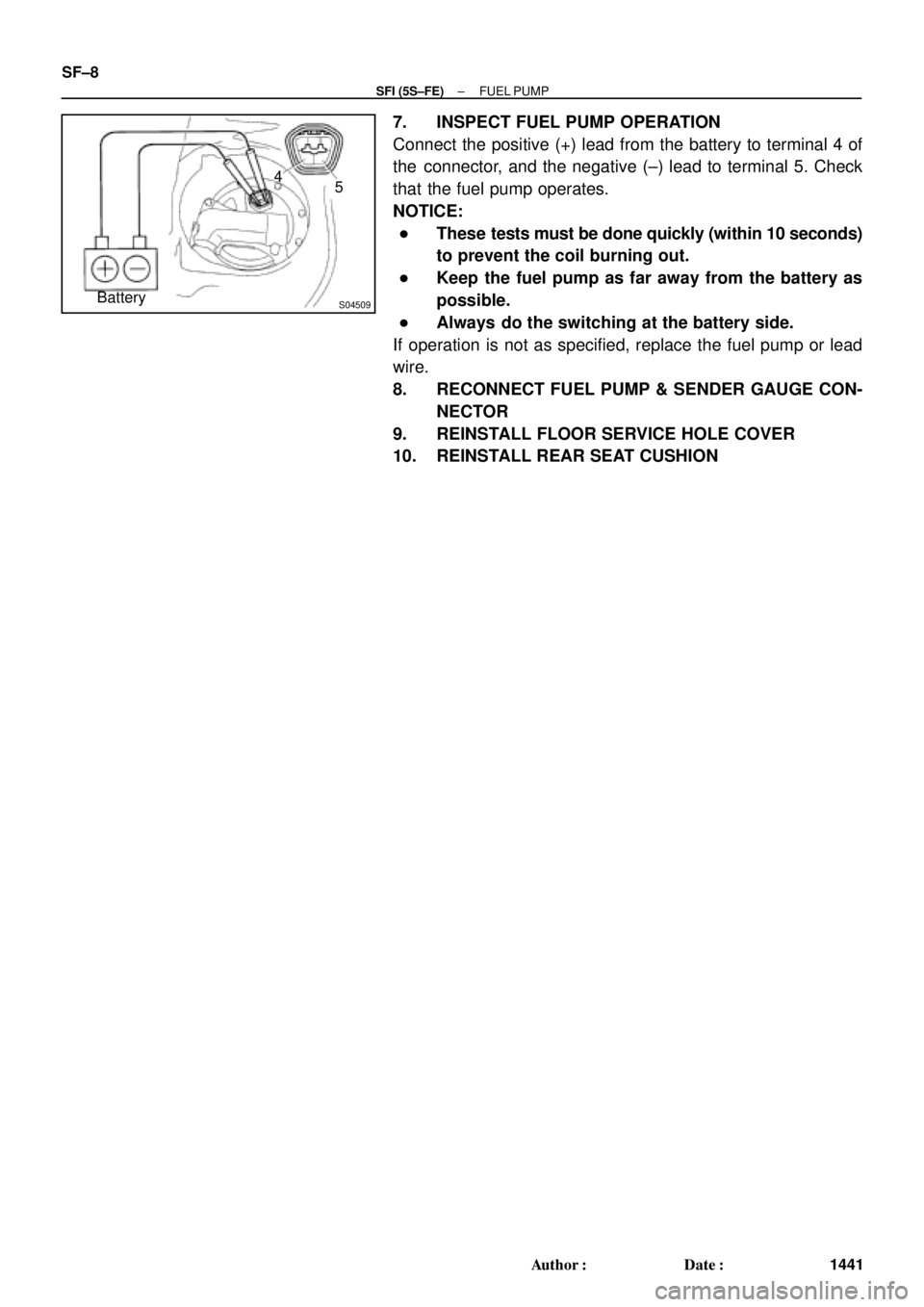
7. INSPECT FUEL PUMP OPERATION
Connect the positive (+) lead from the battery to terminal 4 of
the connector, and the negative (±) lead to terminal 5. Check
that the fuel pump operates.
NOTICE:
�These tests must be done quickly (within 10 seconds)
to prevent the coil burning out.
�Keep the fuel pump as far away from the battery as
possible.
�Always do the switching at the battery side.
If operation is not as specified, replace the fuel pump or lead
wire.
8. RECONNECT FUEL PUMP & SENDER GAUGE CON-
NECTOR
9. REINSTALL FLOOR SERVICE HOLE COVER
10. REINSTALL REAR SEAT CUSHION
Page 3331 of 4592
SF0D8±02
Z19025
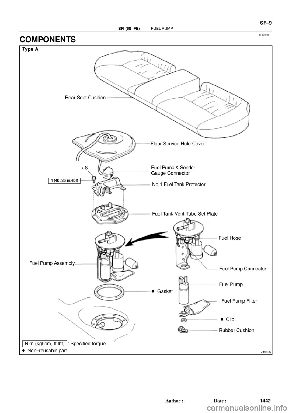
Type A
Rear Seat Cushion
� Gasket
4 (40, 35 in.´lbf)
Floor Service Hole Cover
Fuel Pump & Sender
Gauge Connector
No.1 Fuel Tank Protector
Fuel Tank Vent Tube Set Plate
Fuel Hose
Fuel Pump Connector
Fuel Pump
Fuel Pump Filter
� Clip
Rubber Cushion Fuel Pump Assembly
N´m (kgf´cm, ft´lbf)
� Non±reusable part: Specified torquex 8
± SFI (5S±FE)FUEL PUMP
SF±9
1442 Author�: Date�:
COMPONENTS