Page 3418 of 4592
S06086
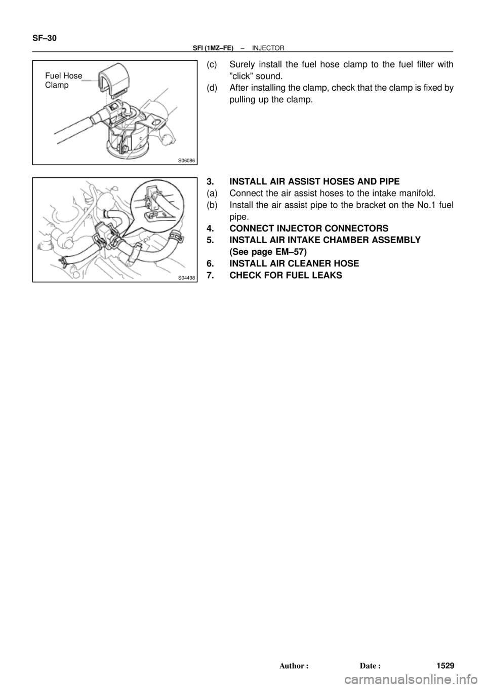
Fuel Hose
Clamp
S04498
SF±30
± SFI (1MZ±FE)INJECTOR
1529 Author�: Date�:
(c) Surely install the fuel hose clamp to the fuel filter with
ºclickº sound.
(d) After installing the clamp, check that the clamp is fixed by
pulling up the clamp.
3. INSTALL AIR ASSIST HOSES AND PIPE
(a) Connect the air assist hoses to the intake manifold.
(b) Install the air assist pipe to the bracket on the No.1 fuel
pipe.
4. CONNECT INJECTOR CONNECTORS
5. INSTALL AIR INTAKE CHAMBER ASSEMBLY
(See page EM±57)
6. INSTALL AIR CLEANER HOSE
7. CHECK FOR FUEL LEAKS
Page 3800 of 4592
 EVAP System Overview
There are a variety of EVAP systems in use with different monitoring strategi")
EVAP SYSTEM OPERATION INFORMATION ± EG005-01 April 27, 2001
Page 2 of 14
Early Type (Non±Intrusive) EVAP System Overview
There are a variety of EVAP systems in use with different monitoring strategies. It is
essential that the EVAP system be correctly identified before beginning diagnosis. The
Repair Manual is the best source for this information. The following information covers
the different systems.
The first system described is the Early Type (Non±Intrusive) EVAP System. Refer to the
Applicable Vehicles chart for applicability information.
Onboard Recovery Valve
(Fill Check Valve)Vapor
Pressure
SensorVapor
Pressure
Sensor
Three Way
VSVVacuum
Check
ValveTank Valve
AssemblyPressure
ValveCanister
To
Manifold
Vacuum
Purge
Valve
Filtered
Air
Air Drain Valve
Air Valve AssemblyAir Inlet ValveAir Inlet LineService
Port
Purge Operation
When the engine has reached
predetermined parameters (closed loop,
engine temp. above 125�F, etc.), stored
fuel vapors are purged from the canister
whenever the purge VSV is opened by
the ECM. At the appropriate time, the
ECM will turn on the purge VSV.
The ECM will change the duty ratio cycle
of the purge VSV thus controlling purge
flow volume. Purge flow volume is
determined by manifold pressure and the
duty ratio cycle of the purge VSV.
Atmospheric pressure is allowed into the
canister to ensure that purge flow is
constantly maintained whenever purge
vacuum is applied to the canister (see
Figure 1).
Early Type
System
Description
Figure 1. Purge OperationFresh Air Inlet
Purge VSV
Page 3803 of 4592
EVAP SYSTEM OPERATION INFORMATION ± EG005-01 April 27, 2001
Page 5 of 14
Late Type (Intrusive EVAP System) (Except ECHO)
Onboard Recovery Valve
(Fill Check Valve)Vapor
Pressure
SensorVacuum
Check
ValveTank Valve
AssemblyTank
Pressure
Valve
Canister
To
Manifold
Vacuum
Purge
VSV
Filtered
Air
Air Drain Valve
Air Valve AssemblyAir Inlet ValveCanister
Closed Valve
Bypass
VSVAir
Inlet LineService
Port
Tank Side
The bypass VSV and the fill check valve
assembly isolates the tank pressure side
from the canister side (see Figure 1).
Canister Side
The bypass VSV and the Fill Check valve
also isolate the canister side from the
tank side (see Figure 2).
Late Type
System
Description
(Continued)
Except ECHO
Figure 1. Fuel Tank Side of System
Except ECHO
Figure 2. Canister Side of System
 (Except ECHO)
Onboard Recovery Valve
(Fill Check Valve)Vapor
Pressure
SensorVacuum
Check
Val")