Page 3345 of 4592
Union Bolt
SST (Union)
Injector Fuel Filter
(On Vehicle)SST
(Clamp)
SST
(Union)
S05522
S05524
Union Bolt
Gasket SST (Union)
SST (Hose)
P01078
SST
(Clamp) O±Ring
Vinyl
Tube")
SF0DJ±03
S05525
SST (Hose)Union Bolt
SST (Union)
Injector Fuel Filter
(On Vehicle)SST
(Clamp)
SST
(Union)
S05522
S05524
Union Bolt
Gasket SST (Union)
SST (Hose)
P01078
SST
(Clamp) O±Ring
Vinyl
Tube SST (Union)SST (Hose)
S05331
± SFI (5S±FE)INJECTOR
SF±23
1456 Author�: Date�:
INSPECTION
1. INSPECT INJECTOR INJECTION
CAUTION:
Keep injector clean of sparks during the test.
(a) Remove the union bolt and 2 gaskets, and disconnect the
fuel inlet hose from the fuel filter outlet.
(b) Connect SST (union and hose) to the fuel filter outlet with
the 2 gaskets and union bolts.
SST 09268±41047 (90405±09015)
Torque: 29 N´m (300 kgf´cm, 21 ft´lbf)
(c) Install the grommet and O±ring to the injector.
(d) Connect SST (union and hose) to the injector, and hold
the injector and union with SST (clamp).
SST 09268±41047 (09268±41100, 09268±41110)
(e) Put the injector into the graduated cylinder.
CAUTION:
Install a suitable vinyl hose onto the injector to prevent
gasoline from splashing out.
(f) Connect a TOYOTA hand±held tester to the DLC3.
(g) Connect the battery negative (±) cable to the battery.
(h) Turn the ignition switch ON and push the TOYOTA hand±
held tester main switch ON.
NOTICE:
Do not start the engine.
(i) Select the ACTIVE TEST mode on the TOYOTA hand±
held tester.
(j) Please refer to the TOYOTA hand±held tester operator's
manual for further details.
Page 3346 of 4592

Z09211
CaliforniaExcept California
S05522
SF±24
± SFI (5S±FE)INJECTOR
1457 Author�: Date�:
(k) If you have no TOYOTA hand±held tester, connect the
positive (+) and negativ")
P01077
ConnectSST
(Wire)
Z09211
CaliforniaExcept California
S05522
SF±24
± SFI (5S±FE)INJECTOR
1457 Author�: Date�:
(k) If you have no TOYOTA hand±held tester, connect the
positive (+) and negative (±) leads from the battery to the
fuel pump connector. (See page SF±6)
(l) Connect SST (wire) to the injector and battery for 15 se-
conds, and measure the injection volume with a gra-
duated cylinder. Test each injector 2 or 3 times.
SST 09842±30070
Volume: 51 ± 63 cm
3 (3.2 ± 3.8 cu in.) per 15 seconds
Difference between each injector:
12 cm
3 (0.7 cu in.) or less
If the injection volume is not as specified, replace the injector.
2. INSPECT LEAKAGE
(a) In the condition above, disconnect the tester probes of
SST (wire) from the battery and check the fuel leakage
from the injector.
SST 09842±30070
Fuel drop: 1 drop or less per 3 minutes
(b) Turn the ignition switch OFF.
(c) Disconnect the negative (±) terminal cable from the bat-
tery.
(d) Remove the SST.
SST 09268±41047, 09842±30070
(e) Disconnect the TOYOTA hand±held tester from the
DLC3.
(f) Reconnect the fuel inlet hose to the fuel filter outlet with
2 new gaskets and the union bolt.
Torque: 29 N´m (300 kgf´cm, 22 ft´lbf)
Page 3394 of 4592
FUEL PUMP
1505 Author�: Date�:
FUEL PUMP
ON±VEHICLE INSPECTION
1. CHECK FUEL PUMP OPERATION
(a) Connect")
S05358
TOYOTA
Hand Held TesterSF079±04
S05353
S05359
Fuel Tube Connector
SF±6
± SFI (1MZ±FE)FUEL PUMP
1505 Author�: Date�:
FUEL PUMP
ON±VEHICLE INSPECTION
1. CHECK FUEL PUMP OPERATION
(a) Connect a TOYOTA hand±held tester to the DLC3.
(b) Turn the ignition switch ON and push the TOYOTA hand±
held tester main switch ON.
NOTICE:
Do not start the engine.
(c) Select the ACTIVE TEST mode on the TOYOTA hand±
held tester.
(d) Please refer to the TOYOTA hand±held tester operator's
manual for further details.
(e) If you have no TOYOTA hand±held tester, connect the
positive (+) and negative (±) leads from the battery to the
fuel pump connector. (See step 7)
(f) Check that there is pressure in the fuel inlet hose from the
fuel filter.
HINT:
If there is fuel pressure, you will hear the sound of fuel flowing.
If there is no pressure, check these parts:
Fusible link
Fuses
EFI main relay
Fuel pump
ECM
Wiring connections
(g) Turn the ignition switch OFF.
(h) Disconnect the TOYOTA hand±held tester from the
DLC3.
2. CHECK FUEL PRESSURE
(a) Check the battery positive voltage is above 12 V.
(b) Disconnect the negative (±) terminal cable from the bat-
tery.
(c) Purchase the new No.1 fuel pipe and take out the fuel
tube connector from its pipe.
Part No. 23801±20041
Page 3395 of 4592

Pipe
SST
(Hose)SST
± SFI (1MZ±FE)FUEL PUMP
SF±7
1506 Author�: Date�:
(d) Remove the fuel hose clamp.
(e) D")
S06086
Fuel Hose
Clamp
S05352
S05364
SST
SST
Retainer
No.1 Fuel
Fuel Tube
Connector (Hose)
Pipe
SST
(Hose)SST
± SFI (1MZ±FE)FUEL PUMP
SF±7
1506 Author�: Date�:
(d) Remove the fuel hose clamp.
(e) Disconnect the No.1 fuel pipe (fuel tube connector) from
the fuel filter outlet.
CAUTION:
�Perform disconnecting operations of the fuel tube
connector (quick type) after observing the precau-
tions. (See page SF±1)
�As there is retained pressure in the fuel pipe line, pre-
vent it from splashing inside the engine compart-
ment.
(f) Install SST (pressure gauge) as shown in the illustration
by using SST and fuel tube connector.
SST 09268±41047, 09268±41250, 09268±45012
(g) Wipe off any splattered gasoline.
(h) Reconnect the negative (±) terminal cable to the battery.
(i) Connect the TOYOTA hand held tester to the DLC3.
(See step 1. check fuel pump operation (a) to (e))
(j) Measure the fuel pressure.
Fuel pressure:
301 ± 347 kPa (3.1 ± 3.5 kgf/cm
2, 44 ± 50 psi)
If pressure is high, replace the fuel pressure regulator.
If pressure is low, check these parts:
Fuel hoses and connections
Fuel pump
Fuel filter
Fuel pressure regulator
(k) Disconnect the TOYOTA hand±held tester from the
DLC3.
(l) Start the engine.
(m) Measure the fuel pressure at idle.
Fuel pressure:
301 ± 347 kPa (3.1 ± 3.5 kgf/cm
2, 44 ± 50 psi)
(n) Stop the engine.
(o) Check that the fuel pressure remains as specified for 5
minutes after the engine has stopped.
Fuel pressure:
147 kPa (1.5 kgf/cm
2, 21 psi) or more
If pressure is not as specified, check the fuel pump, pressure
regulator and/or injectors.
Page 3396 of 4592
FUEL PUMP
1507 Author�: Date�:
(p) After checking fuel pressure, disconnect the negative (±)
terminal cable")
S05351
S06086
Fuel Hose
Clamp
S04508
Ohmmeter
4 5
S04509
4 5
Battery SF±8
± SFI (1MZ±FE)FUEL PUMP
1507 Author�: Date�:
(p) After checking fuel pressure, disconnect the negative (±)
terminal cable from the battery and carefully remove the
SST and fuel tube connector to prevent gasoline from
splashing.
SST 09268±41047, 09268±41250, 09268±45012
(q) Reconnect the No.1 fuel pipe (fuel tube connector).
CAUTION:
Perform connecting operations of the fuel tube connector
(quick type) after observing the precautions.
(See page SF±1)
(r) Surely install the fuel hose clamp to the fuel filter with
ºclickº sound.
(s) After installing the clamp, check that the clamp is fixed by
pulling up the clamp.
(t) Reconnect the negative (±) terminal cable to the battery.
(u) Check for fuel leaks.
3. REMOVE REAR SEAT CUSHION
4. REMOVE FLOOR SERVICE HOLE COVER
5. DISCONNECT FUEL PUMP & SENDER GAUGE
CONNECTOR
6. INSPECT FUEL PUMP RESISTANCE
Using an ohmmeter, measure the resistance between terminals
4 and 5.
Resistance: 0.2 ± 3.0 W at 20°C (68°F)
If the resistance is not as specified, replace the fuel pump.
7. INSPECT FUEL PUMP OPERATION
Connect the positive (+) lead from the battery to terminal 4 of
the connector, and the negative (±) lead to terminal 5. Check
that the fuel pump operates.
NOTICE:
�These tests must be done quickly (within 10 seconds)
to prevent the coil burning out.
�Keep the fuel pump as far away from the battery as
possible.
�Always do the switching at the battery side.
Page 3398 of 4592
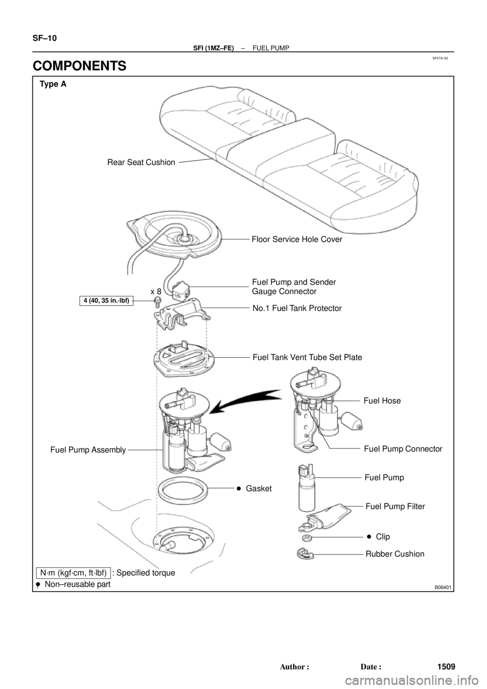
SF07A±02
B06401
Type A
Rear Seat Cushion
� Gasket
4 (40, 35 in.´lbf)
Floor Service Hole Cover
Fuel Pump and Sender
Gauge Connector
No.1 Fuel Tank Protector
Fuel Tank Vent Tube Set Plate
Fuel Hose
Fuel Pump Connector
Fuel Pump
Fuel Pump Filter
Rubber Cushion
N´m (kgf´cm, ft´lbf)
� Non±reusable part: Specified torque
� Clip
Fuel Pump Assembly
x 8
SF±10
± SFI (1MZ±FE)FUEL PUMP
1509 Author�: Date�:
COMPONENTS
Page 3399 of 4592
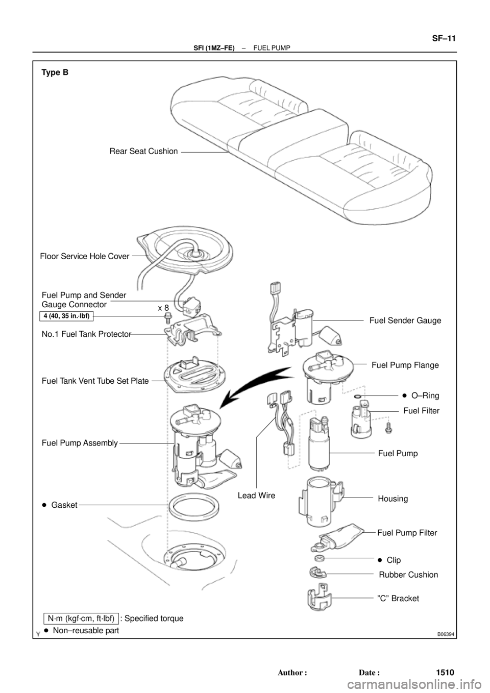
B06394
Type B
Rear Seat Cushion
� Gasket
4 (40, 35 in.´lbf)
Floor Service Hole Cover
Fuel Pump and Sender
Gauge Connector
No.1 Fuel Tank Protector
Fuel Tank Vent Tube Set Plate
N´m (kgf´cm, ft´lbf) : Specified torque Fuel Pump Assemblyx 8
� Clip
Rubber Cushion Fuel Pump FilterFuel Pump
HousingFuel Filter
ºCº Bracket
� O±Ring
Fuel Sender Gauge
Fuel Pump Flange
Lead Wire
� Non±reusable part
± SFI (1MZ±FE)FUEL PUMP
SF±11
1510 Author�: Date�:
Page 3400 of 4592
FUEL PUMP
1511 Author�: Date�:
REMOVAL
CAUTION:
Do not smoke or work near an open flame when working on
the fuel pump.
1. REMOVE REAR SEAT CUSH")
SF07B±04
S04583
S04592
Vinyl Bag SF±12
± SFI (1MZ±FE)FUEL PUMP
1511 Author�: Date�:
REMOVAL
CAUTION:
Do not smoke or work near an open flame when working on
the fuel pump.
1. REMOVE REAR SEAT CUSHION
2. REMOVE FLOOR SERVICE HOLE COVER
(a) Take out the floor carpet.
(b) Remove the service hole cover.
HINT:
At the time of installation, plaese refer to the following items.
Check for fuel leakage.
3. DISCONNECT FUEL PUMP & SENDER GAUGE
CONNECTOR
4. REMOVE NO.1 FUEL TANK PROTECTOR
Remove the 2 bolts and No.1 fuel tank protector.
Torque: 4 N´m (40 kgf´cm, 35 in.´lbf)
5. DISCONNECT FUEL TUBE (FUEL TUBE CONNEC-
TOR)
CAUTION:
�Perform disconnecting and connecting operations of
the fuel tube connector (quick type) after observing
the precautions. (See page SF±1)
�As there is retained pressure in the fuel pipe line, pre-
vent it from splashing inside the vehicle compart-
ment.
6. REMOVE FUEL PUMP ASSEMBLY FROM FUEL TANK
(a) Remove the 6 bolts and fuel tank vent tube set plate.
Torque: 4 N´m (40 kgf´cm, 35 in.´lbf)
(b) Pull out the fuel pump assembly.
(c) Remove the gasket from the pump assembly.
NOTICE:
�Do not damage the fuel pump filter.
�Be careful that the arm of the sender gauge should
not bent.
HINT:
At the time of installation, plaese refer to the following items.
Install a new gasket to the pump assembly.