Page 252 of 349
RS0IX–01
H03424: Specified torqueN·m (kgf·cm, ft·lbf)Side and Curtain Shield Airbag Sensor Assembly
21 (210, 15)
Front Seat Outer Belt Retractor
5.0 (51, 44 in.·lbf)
42 (430, 31)
Center Piller Garnish
Rear Door Scuff Plate
Front Door Scuff Plate
RS–34– SUPPLEMENTAL RESTRAINT SYSTEMSIDE AND CURTAIN SHIELD AIRBAG SENSOR
ASSEMBLY
SIDE AND CURTAIN SHIELD AIRBAG SENSOR ASSEMBLY
COMPONENTS
Page 256 of 349

RS0J1–01
H03425
H03674
RS–38– SUPPLEMENTAL RESTRAINT SYSTEMSIDE AND CURTAIN SHIELD AIRBAG SENSOR
ASSEMBLY
INSTALLATION
NOTICE:
�Never use SRS parts from another vehicle. When re-
placing parts, replace them with new ones.
�Never reuse the side and curtain shield airbag sensor
assembly involved in a collision when the airbag has
deployed.
�Never repair a sensor in order to reuse it.
1. INSTALL SIDE AND CURTAIN SHILD AIRBAG SEN-
SOR
(a) Install the side and curtain shield airbag assembly with
the 2 bolts and nut.
Torque: 21 N·m (210 kgf·cm, 15 ft·lbf)
(b) Connect the side and curtain shild airbag sensor connec-
tor.
NOTICE:
�Installation of the connector is done with the sensor
assembly installed. Make sure the sensor assembly
is installed with the specified torque.
�If the sensor assembly has been dropped, or there are
cracks, dents or other defects in the case, bracket or
connector, replace the sensor assembly with a new
one.
�When installing the sensor assembly, take care that
the SRS wiring does not interfere with other parts and
is not pinched between other parts.
�After installation, shake the sensor assembly to
check that there is no looseness.
2. INSTALL FRONT SEAT OUTER BELT RETRACTOR
(See pub. No. RM599E on page BO–159)
(a) Install the retractor with the 2 bolts.
Torque:
Upper bolt: 5.0 N·m (51 kgf·cm, 44 in.·lbf)
Lower bolt: 42 N·m (430 kgf·cm, 31 ft·lbf)
(b) Connect the pretensioner connecter.
3. INSTALL CENTER PILLAR LOWER GARNISH
4. INSTALL FRONT AND REAR DOOR SCUFF PLATE
Page 274 of 349
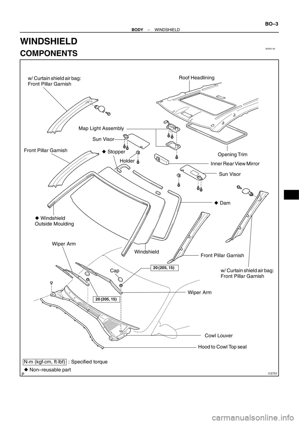
BO0IO–04
I12751
Roof Headlining
Sun Visor Opening Trim
Holder Front Pillar Garnish
� Windshield
Outside Moulding
Front Pillar Garnish Windshield Wiper Arm
N·m (kgf·cm, ft·lbf) : Specified torque
� Non–reusable partWiper Arm
Sun Visor
20 (205, 15)
20 (205, 15)
� Dam Inner Rear View Mirror
Cowl Louver Map Light Assembly
Cap
Hood to Cowl Top seal � Stopper
w/ Curtain shield air bag:
Front Pillar Garnish
w/ Curtain shield air bag:
Front Pillar Garnish
– BODYWINDSHIELD
BO–3
WINDSHIELD
COMPONENTS
Page 280 of 349
 Use a scraper to remove any excessive or protruding
adhesive.
(d) Hold the windshield glass in pl")
BO3986
BO3671AdhesiveAdhesive
H03503
H11626
Pillar Garnish
Cover
2 Clips
– BODYWINDSHIELD
BO–9
(c) Use a scraper to remove any excessive or protruding
adhesive.
(d) Hold the windshield glass in place securely with protec-
tive tape or equivalent until the adhesive hardenes.
NOTICE:
Take care not to drive the vehicle during the time described
in the table below.
TemperatureMinimum time prior to driving the vehicle
35�C (95�F)1.5 hours
20�C (68�F)5 hours
5�C (41�F)24 hours
11. INSPECT FOR LEAKAGE AND REPAIR
(a) Do a leak test after the hardening time has elapsed.
(b) Seal any leakage with sealant.
Part No. 08833–00030 or equivalent
12. APPLY ADHESIVE AT MOULDING INSTALLATION
AREA
Coat the glass with adhesive at the moulding installation area.
Part No. 08833–00030 or equivalent
13. INSTALL WINDSHIELD MOULDING
Place the moulding onto the body and tap it by hand.
14. INSTALL THESE PARTS:
(a) Install the front part of roof headlining.
(b) Install the inner rear view mirror
(c) w/ Curtain Shield Air Bag:
(1) Remove the protection cover.
(2) Install the 2 bolts.
Torque: 5 N·m (51 kgf·cm, 44 in.·lbf)
(3) Install the front pillar garnish.
(4) Install the pillar garnish cover and bolt.
NOTICE:
Be sure to tighten the bolt.
(5) Fell the pillar garnish cover.
(d) Install the front pillar garnishes.
Page 281 of 349
BO–10
– BODYWINDSHIELD
(e) Install the upper part of roof headlining.
(f) Install the assist grip.
(g) Install the map light assembly.
(h) Install the sun visors and holders.
(i) Install the cowl louver.
(j) Install the weatherstrip.
(k) Install the front wiper arms.
Torque: 20 N·m (205 kgf·cm, 15 ft·lbf)
Page 284 of 349
BO19J–02
I12662
Reinforcement
No.1 BraceFront Pillar Garnish
Instrument Panel
Front Door Opening Trim
Rear Door
Scuff Plate
Glove Compartment Door Heater Control
Assembly
No.1 Under Cover
Rear Console Box
Parking Brake Hole Cover Steering Wheel Pad Steering Wheel Combination Switch Column CoverLower Finish Panel Cluster Finish Panel Combination Meter No.1 Register
Center Cluster
Finish Panel
Front Door Scuff Plate Cowl Side Trim
Center Pillar Lower GarnishRear Door Opening Trim
B C
D
F G
A
A
B
CC
D
E
E
E
EE
E
E
EE
F
G
G
G
HHH
x 4Front Ash Receptacle
34 (350, 25)
18 (185, 13)
: Specified torqueN·m (kgf·cm, ft·lbf)
Curtain Shield Airbag
F
F
w/ Curtain shield air bag:
Front Pillar Garnish
– BODYINSTRUMENT PANEL
BO–13
INSTRUMENT PANEL
COMPONENTS
Page 290 of 349
BO2J4–01
H03666
H03665
H03664
H03663
– BODYINSTRUMENT PANEL
BO–19
INSTALLATION
1. INSTALL THESE PARTS:
(a) Install the reinforcement.
(b) Install the No.1 brace.
2. INSTALL INSTRUMENT PANEL
(a) Install the 6 screws and 3 nuts.
(b) Install the passenger airbag assembly with the 2 bolts.
Torque: 18 N·m (185 kgf·cm, 13 ft·lbf)
3. INSTALL HEATER CONTROL ASSEMBLY
(See Pub. No.RM599E on page AC–111)
4. INSTALL CENTER CLUSTER FINISH PANEL
Install the panel, then connect the connectors.
5. INSTALL REAR CONSOLE BOX
(a) Install the console box with the 2 bolts and 4 caps, 4
screws.
(b) M/T:
Install the shift lever knob.
6. INSTALL PARKING BRAKE HOLE COVER
7. INSTALL GLOVE COMPARTMENT DOOR
Install the glove compartment door with the 2 glove shaft.
Page 291 of 349

H03662
: 3 Clips
H03661
: 3 Clips
H03660
: 3 Clips
H03659
BO–20
– BODYINSTRUMENT PANEL
8. INSTALL NO.1 UNDER COVER
Install the No.1 under cover.
9. INSTALL NO.1 REGISTER
Install the No.1 register.
10. INSTALL COMBINATION METER
11. INSTALL CLUSTER FINISH PANEL
(a) Install the cluster finish panel, then connect the connec-
tor.
(b) Install the 2 screws.
12. INSTALL THESE PARTS:
(See Pub. No. RM 599E, page SR–13)
(a) Install the steering column.
(b) Install the combination switch.
(c) Install the column cover.
13. INSTALL LOWER FINISH PANEL
(a) Install the lower finish panel with the 2 screws.
(b) Install the hood lock control lever.
14. INSTALL STEERING WHEEL
(See Pub. No. RM 599E, page SR–13)
15. INSTALL THESE PARTS:
(a) Install the front seats.
Torque: 37 N·m (375 kgf·cm, 27 ft·lbf)
(b) Install the center pillar lower covers.
(c) Install the rear door scuff plates.
(d) Install the rear door opening trims.
(e) Install the cowl side trims.
(f) Install the front door scuff plates.
Side and Curtain Shield Airbag Sensor Assembly
21 (210, 15)
Front Seat Outer Belt Retractor
5.0 (51, 44 in.·lbf)
42 (430, 31)
Center Piller G")
 Install the upper part of roof headlining.
(f) Install the assist grip.
(g) Install the map light assembly.
(h) Install the sun visors and holders.
(i) Install the cowl")

 Install the reinforcement.
(b) Install the No.1 brace.
2. INSTALL INSTRUMENT PANEL
(a)")