Page 215 of 349
SR–15
7. INSTALL VANE PLATES
Install the 10 plates with the round end facing outward.
8. INSTAL")
F01315
Round End
F01316
F03722
Press
– STEERINGPOWER STEERING VANE PUMP (2C–T, 2C–TE,
1CD–FTV)SR–15
7. INSTALL VANE PLATES
Install the 10 plates with the round end facing outward.
8. INSTALL SIDE REAR PLATE
(a) Coat a new O–ring with power steering fluid and install it
to the side rear plate.
(b) Align the holes of the plate and 2 straight pins, and install
the plate.
9. INSTALL WAVE WASHER
Install the washer so that its protrusions fit into the slots in the
side rear plate.
10. INSTALL REAR HOUSING
(a) Coat a new O–ring with power steering fluid and install it
to the rear housing.
(b) Install the housing and use a press to push down on the
wave washer hard enough to compress it.
NOTICE:
�Do not apply too much pressure.
�Be careful not to damage the O–ring.
(c) Install a new snap ring.
11. INSTALL SPRING AND FLOW CONTROL VALVE
Install the valve facing the correct direction
(See page SR–6).
12. INSTALL PRESSURE PORT UNION
(a) Coat a new O–ring with power steering fluid and install it
to the pressure pore union.
(b) Install the union.
Torque: 69 N·m (700 kgf·cm, 51 ft·lbf)
13. INSTALL SUCTION PORT UNION
(a) Coat a new O–ring with power steering fluid and install it
to the suction port union.
(b) Install the bolt.
Torque: 13 N·m (130 kgf·cm, 9 ft·lbf)
14. MEASURE PS VANE PUMP ROTATING TORQUE
(See page SR–9)
Page 216 of 349

INSTALLATION
1. INSTALL PULLEY COVER
Install the pulley cover to the PS vane pump with the bolt.")
SR0WG–01
F04155
SST
F08958
SR–16– STEERINGPOWER STEERING VANE PUMP (2C–T, 2C–TE,
1CD–FTV)
INSTALLATION
1. INSTALL PULLEY COVER
Install the pulley cover to the PS vane pump with the bolt.
Torque: 39 N·m (400 kgf·cm, 29 ft·lbf)
2. INSTALL PS VANE PUMP ASSEMBLY
Install the PS vane pump to the pulley bracket and engine with
the 3 bolts.
Torque: 39 N·m (400 kgf·cm, 29 ft·lbf)
3. CONNECT PRESSURE FEED TUBE
Place a new gasket to the pressure feed tube and connect them
with the union bolt.
Torque: 52 N·m (525 kgf·cm, 38 ft·lbf)
4. CONNECT RETURN HOSE
Connect the return hose with the clip.
5. INSTALL VANE PUMP PULLEY
(a) Install the woodruff key to the vane pump shaft.
(b) Install the vane pump pulley.
(c) Using SST to stop the pulley rotating, torque the nut.
SST 09960–10010 (09962–01000, 09963–01000)
Torque: 43 N·m (440 kgf·cm, 32 ft·lbf)
6. INSTALL DRIVE BELT
(a) Install the drive belt to the pulley.
(b) Adjust drive belt tension with the belt tension adjusting
bolt (See page SR–1).
(c) Torque the idler pulley set nut.
Torque: 38 N·m (390 kgf·cm, 28 ft·lbf)
7. BLEED POWER STEERING SYSTEM
(See Pub. No. RM599E on page SR–5)
Page 227 of 349
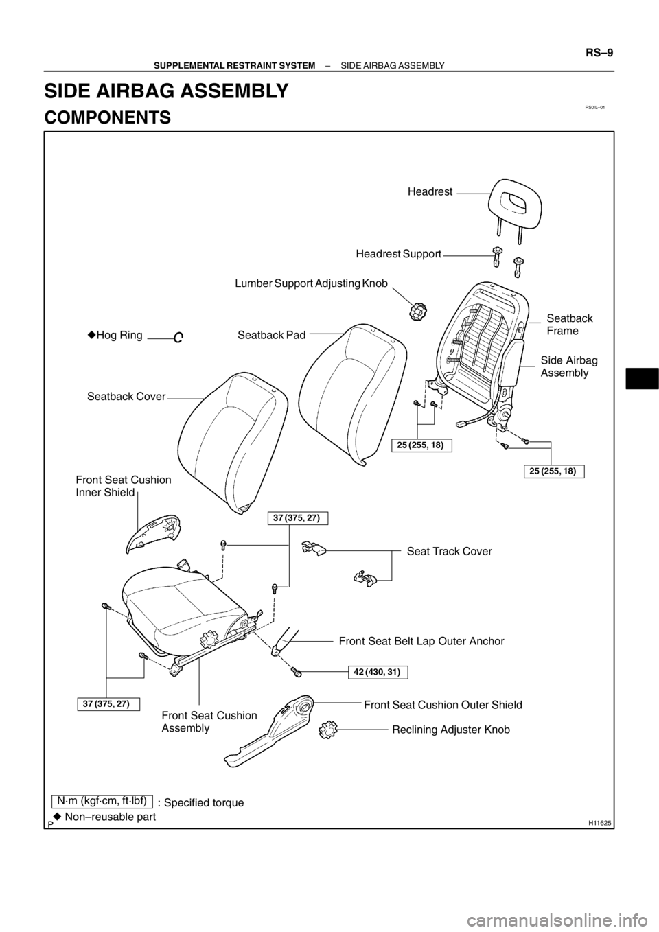
RS0IL–01
H11625
: Specified torque
� Non–reusable partHeadrest
Headrest Support
Lumber Support Adjusting Knob
Seatback Pad
Seatback CoverSeatback
Frame
25 (255, 18)
25 (255, 18)
Side Airbag
Assembly
Front Seat Cushion
Assembly
37 (375, 27)
37 (375, 27)
Front Seat Belt Lap Outer Anchor
42 (430, 31)
Front Seat Cushion Outer Shield
Reclining Adjuster Knob Front Seat Cushion
Inner Shield�Hog Ring
N·m (kgf·cm, ft·lbf)Seat Track Cover
– SUPPLEMENTAL RESTRAINT SYSTEMSIDE AIRBAG ASSEMBLY
RS–9
SIDE AIRBAG ASSEMBLY
COMPONENTS
Page 237 of 349

RS0IQ–01
H03410
H03411
H03408
– SUPPLEMENTAL RESTRAINT SYSTEMSIDE AIRBAG ASSEMBLY
RS–19
INSTALLATION
NOTICE:
Never use airbag parts from another vehicle. When replac-
ing parts, replace them with new parts.
1. INSTALL THESE PARTS TO SEATBACK FRAME
(a) Install the seatback pad.
(b) Install the hog rings and seatback cover.
(c) Hang the hook of the seatback cover.
2. INSTALL SEATBACK TO SEAT CUSHION ASSEMBLY
Using a torx wrench, install the 4 screws and seatback assem-
bly.
Torx wrench: T40 (Part No.09042–00020 or locally
manufactured tool)
Torque: 25 N·m (255 kgf·cm, 18 ft·lbf)
3. INSTALL THESE PARTS TO FRONT SEAT ASSEMBLY
(a) Install the 2 headrest supports.
(b) Install the headrest.
(c) Install the lumber support adjusting knob.
(d) Install the front seat inner shield.
4. INSTALL FRONT SEAT
(a) Mount the seat to the vehicle.
(b) Connect the side airbag connector.
(c) Install the outer bolt and inner bolt on the front side after
sliding the seat to the rearmost position.
Torque: 37 N·m (375 kgf·cm, 27 ft·lbf)
(d) Tighten the bolts on the rear side temporarily, tighten
them completely starting from the bolt on the inner side.
Torque: 37 N·m (375 kgf·cm, 27 ft·lbf)
(e) Install the front seat belt lap outer anchor.
Torque: 42 N·m (430 kgf·cm, 31 ft·lbf)
(f) Install the front seat cushion outer shield and reclining ad-
juster knob.
(g) Install the 2 seat track covers.
Page 238 of 349
RS0IR–01
H11612
Roof Headlining
Front Pillar GarnishCenter Pillar Upper Garnish
Center Pillar Lower Garnish Front Seat Outer Belt Assist Grip
Front Door Operating Trim
Front Door Scuff Plate
Rear Door Scuff Plate Rear Door Operating Trim
Map Light Sun Visor
Pillar Garnish Cover
H11611
Sedan Model Liftback Model Wagon Model
Roof Side
Inner Garnish
Side Seatback
Rear Seat CushionDeck Trim
Side Board
Rear Floor
Carpet Deck Side Trim
Cover and Panel
Tonneau
Cover
Rear Floor
Finish Plate Rear Seat
Outer Belt
Roof Side
Inner Garnish
Side Seatback
Roof Side
Inner Garnish
Rear Seatback
Assembly
Rear Side
Seatback
Room
Partition
Net
N·m (kgf·cm, ft·lbf): Specified torque
42 (430, 31)
21 (214, 15)
21 (214, 15)
21 (214, 15)
RS–20
– SUPPLEMENTAL RESTRAINT SYSTEMCURTAIN SHIELD AIRBAG ASSEMBLY
CURTAIN SHIELD AIRBAG ASSEMBLY
COMPONENTS
Page 239 of 349
H11621
Instrument Panel
Column CoverNo.1 Register
Steering Wheel Combination Meter
Steering Wheel PadHeater Control Assembly
Cluster Finish Panel
Glove Compartment DoorFront Ash Receptacle
Lower Finish Panel
Rear Console Box No.1 Under Cover
Shift Knob
Parking Brake Hole Cover Combination Switch
Center Cluster Finish Panel
78 (790, 58)
N·m (kgf·cm, ft·lbf) : Specified torque
Cowl Side Panel
18 (184, 13)
Cover
Cover
– SUPPLEMENTAL RESTRAINT SYSTEMCURTAIN SHIELD AIRBAG ASSEMBLY
RS–21
Page 240 of 349
H11619
LH Curtain Shield Airbag AssemblyRH Curtain Shield Airbag Assembly
Curtain Shield Airbag ConnectorGrommet Grommet GrommetCurtain Shield Airbag Connector
9.8 (100, 87 in.·lbf)
: Specified torqueN·m (kgf·cm, ft·lbf)
9.8 (100, 87 in.·lbf)
5 (51, 44 in.·lbf)
H11620
Curtain Shield Airbag
(Deployment Section)
Inflater
RS–22
– SUPPLEMENTAL RESTRAINT SYSTEMCURTAIN SHIELD AIRBAG ASSEMBLY
Page 250 of 349
(7)
(4)
(6)
(1)(2)(3)
H11613
(1)(2)(3)(4)
(5)
RS–32
– SUPPLEMENTAL RESTRAINT SYSTEMCURTAIN SHIELD AIRBAG ASSEMBLY
INSTALLATION
NOTICE:
�Never use airbag parts from another ve")
RS0IW–01
H11615
(5)(7)
(4)
(6)
(1)(2)(3)
H11613
(1)(2)(3)(4)
(5)
RS–32
– SUPPLEMENTAL RESTRAINT SYSTEMCURTAIN SHIELD AIRBAG ASSEMBLY
INSTALLATION
NOTICE:
�Never use airbag parts from another vehicle. When
replacing parts, replace them with new parts.
�Make sure that the curtain shield airbag assembly is
installed with the specified torque.
�If the curtain shield airbag assembly has been
dropped, or there are cracks, dents or other defects
in the case or connector, replace the curtain shield
airbag assembly with a new one.
�When installing the curtain shield airbag assembly,
take care it is not pinched between other parts.
1. INSTALL CURTAIN SHIELD AIRBAG ASSEMBLY
(a) Connect the connector of the curtain shield airbag sub
wire harness then lock it.
(b) In order shown in the illustration, install the curtain shield
airbag with the bolts and grommets.
Torque:
Nuts: 9.8 N·m (100 kgf·cm, 87 in.·lbf)
Bolts: 5 N·m (51 kgf·cm, 44 in.·lbf)
CAUTION:
Pay attention for not causing twisting.
(c) Install the instrument panel assembly. (See page
BO–19)
2. INSTALL CURTAIN SHIELD AIRBAG
(IN CASE WITHOUT INSTALLING INFLATER)
In order shown in the illustration, install the deployment section
of the curtain shield airbag with the bolts and grommet.
Torque: 5 N·m (51 kgf·cm, 44 in.·lbf)
CAUTION:
Pay attention for not causing twisting.
3. INSTALL ROOF HEADLINING
�Sedan model (See page BO–25)
�Liftback model (See page BO–30)
�Wagon model (See page BO–36)


: Specified torqu")