Page 190 of 349
BR11N–01
F08962
Brake PedalPedal PadReturn Spring
Cushion Plate Collar� Bushing Brake Pedal BracketStop Light Switch Clevis Pin
Clip
Stop Light Switch Connector
� Bushing
: Specified torque
N·m (kgf·cm, ft·lbf)
� Non–reusable part
Brake Pedal
Pedal Pad
Clevis Pin
Clip
Stop Light Switch
Stop Light Switch Connector
Brake Pedal Bracket
� Bushing
Collar
� BushingReturn SpringCushion Plate
Pedal Pad
Brake Pedal
Brake Pedal
Pedal Pad
Lithium soap base glycol grease
RHD M/T
A/T
LHD M/T
A/T
36.8 (375, 27)
36.8 (375, 27)
– BRAKEBRAKE PEDAL
BR–1
BRAKE PEDAL
COMPONENTS
Page 191 of 349
BR11O–01
F08965Non–reusable part N·m (kgf·cm, ft·lbf) : Specified torque�Vacuum Pump
� Gasket Vacuum Hose
Casing
Rotor
BladeStraight
Pin
End Cover Check Valve
Union � O–Ring
Vacuum Hose
� O–Ring
� Gasket
� Gasket
� O–Ring
Oil Hose
Straight Pin
21 (214, 15)
74 (750, 54)
14 (140, 10)
7.8 (80, 68 in.·lbf)
� Snap Ring
Coupling
BR–2
– BRAKEVACUUM PUMP (1CD–FTV)
VACUUM PUMP (1CD–FTV)
COMPONENTS
Page 196 of 349
BR11S–01
F08980
F08981
F08982
New O–Ring
F08970
F08969
– BRAKEVACUUM PUMP (1CD–FTV)
BR–7
REASSEMBLY
1. INSTALL COUPLING
(a) Place the coupling to the rotor shaft.
(b) Install a new snap ring to the rotor shaft.
2. INSTALL ROTOR INTO CASING
Coat the rotor with engine oil, and install it to the rotor shaft.
3. INSTALL 5 BLADES
(a) Coat the 5 blades with engine oil.
(b) Install the 5 blades with the round end facing outward.
HINT:
Be sure that the blades and rotor surfaces are even.
4. INSTALL END COVER
(a) Coat 2 new O–rings with engine oil, and place them to the
casing.
(b) Place the vacuum pump on the vise, as shown in the il-
lustration.
NOTICE:
Do not tighten the vise.
(c) Place the end cover, and temporarily install the 3 bolts.
(d) Using a pin punch and hammer, drive in the 2 straight
pins.
(e) Using soft jaws on the vise, place the vacuum pump in the
vise.
NOTICE:
Do not tighten the vise too tightly.
(f) Tighten the 3 bolts.
Torque: 7.8 N·m (80 kgf·cm, 69 in.·lbf)
Page 197 of 349
F08984
New Gasket
F08985
New Gasket
New Gasket BR–8
– BRAKEVACUUM PUMP (1CD–FTV)
5. INSTALL CHECK VALVE
Install the check valve with a new gasket.
Torque: 74 N·m (750 kgf·cm, 54 ft·lbf)
6. INSTALL VACUUM HOSE UNION
Install the vacuum hose union and 2 new gaskets with the union
bolt.
Torque: 14 N·m (140 kgf·cm, 10 ft·lbf)
HINT:
Align and insert the union pin into the matching hole of the cas-
ing.
Page 198 of 349
BR11T–01
������
������F08964
New O–RingVacuum Hose
Oil Hose
– BRAKEVACUUM PUMP (1CD–FTV)
BR–9
INSTALLATION
1. INSTALL VACUUM PUMP
(a) Coat 2 new O–rings with engine oil, and install them to the
vacuum pump.
(b) Insert the vacuum pump, align the coupling with slit of the
camshaft.
(c) Install the 2 bolts.
Torque: 21 N·m (214 kgf·cm, 15 ft·lbf)
2. CONNECT 2 VACUUM HOSES AND OIL HOSE
Page 206 of 349
SR0WB–01
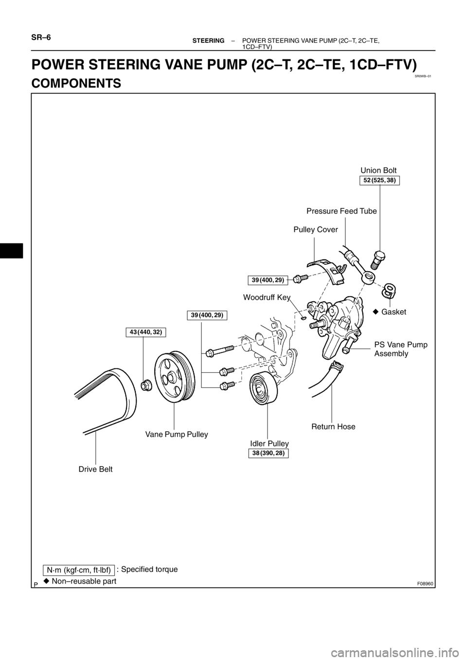
F08960
� Gasket Union Bolt
Pressure Feed Tube
PS Vane Pump
Assembly Woodruff Key
Vane Pump Pulley
Drive Belt
Idler PulleyReturn Hose
N·m (kgf·cm, ft·lbf): Specified torque
� Non–reusable part
Pulley Cover
43 (440, 32)
39 (400, 29)
39 (400, 29)
38 (390, 28)
52 (525, 38)
SR–6– STEERINGPOWER STEERING VANE PUMP (2C–T, 2C–TE,
1CD–FTV)
POWER STEERING VANE PUMP (2C–T, 2C–TE, 1CD–FTV)
COMPONENTS
Page 207 of 349
F03716
N·m (kgf·cm, ft·lbf): Specified torque
� Non–reusable partPressure Port Union
� Shorter Straight Pin
� O–Ring � Snap Ring � O–Ring
� Longer Straight PinSide Front Plate
Flow Control Valve
Spring
� Oil Seal
Front HousingSuction Port UnionVane Pump
Shaft
Power steering fluid
69 (700, 51)
13 (130, 9)
� O–Ring
� O–Ring
� O–Ring � Snap Ring
Cam Ring
Rear Housing
Wave Washer � O–Ring
Side Rear Plate Vane Pump RotorVane Plate
x10
– STEERINGPOWER STEERING VANE PUMP (2C–T, 2C–TE,
1CD–FTV)SR–7
Page 209 of 349
SR–9
DISASSEMBLY
NOTICE:
When using a vise, do not overtighten it.
1. MEASURE PS VANE PUM")
SR0WD–01
F03717
F03718
F03719
Vinyl Tape
– STEERINGPOWER STEERING VANE PUMP (2C–T, 2C–TE,
1CD–FTV)SR–9
DISASSEMBLY
NOTICE:
When using a vise, do not overtighten it.
1. MEASURE PS VANE PUMP ROTATING TORQUE
(a) Check that the pump rotates smoothly without abnormal
noise.
(b) Temporarily install the vane pump pulley set nut.
(c) Using a torque wrench, check the pump rotating torque.
Rotating torque:
0.3 N·m (2.8 kgf·cm, 2.4 in.·lbf) or less
2. REMOVE SUCTION PORT UNION
(a) Remove the bolt and suction port union.
(b) Remove the O–ring from the union.
3. REMOVE PRESSURE PORT UNION
(a) Remove the pressure port union.
(b) Remove the O–ring from the union.
4. REMOVE FLOW CONTROL VALVE AND SPRING
5. REMOVE REAR HOUSING, WAVE WASHER AND SIDE
REAR PLATE
(a) Using 2 screwdrivers, remove the snap ring.
(b) To prevent oil seal lip damage, wind vinyl tape on the ser-
rated part of the vane pump shaft.
(c) Using a plastic hammer, tap out the rear housing, wave
washer and side rear plate.
(d) Remove the O–ring from the rear housing.
(e) Remove the O–ring from the side rear plate.
6. REMOVE CAM RING AND 10 VANE PLATES
NOTICE:
Be careful not to drop the plate.
7. REMOVE VANE PUMP SHAFT WITH VANE PUMP RO-
TOR AND SIDE FRONT PLATE
8. REMOVE VANE PUMP ROTOR AND SIDE FRONT
PLATE
(a) Using a screwdriver, remove the snap ring from the vane
pump shaft.
(b) Remove the vane pump rotor and side front plate.
(c) Remove the 2 O–rings from the side front plate.
9. REMOVE SHORTER STRAIGHT PIN
Using pliers, remove the shorter straight pin from the side front
plate.


BR–7
REASSEMBLY
1. INSTALL COUPLING
(a) Place the coupling to the rotor shaft.
(b) Install a new snap ring")

5. INSTALL CHECK VALVE
Install the check valve with a new gasket.
Torque: 74 N·m (750 kgf·cm, 54 ft·lbf)
6. IN")