Page 64 of 349
PP060–04
PP–20
– PREPARATIONBODY
BODY
EQUIPMENT
Clip remover
Torque wrench
TapeTo avoid surface damage
Adhesive tapeTo avoid surface damage
Adhesive
Cleaner
Shop rag
Knife
Heat light
Piano wire
Page 78 of 349
SS–8
– SERVICE SPECIFICATIONSMANUAL TRANSAXLE (E251)
Transmission case x Transaxle case
2930022
Transmission oil pipe x Transaxle case1717513
Reverse shift arm bracket assembly x Transaxle case1717513
Transmission oil pump assembly x Transaxle case1717513
Transaxle case receiver x Transaxle case7.47565 in.·lbf
Clutch release fork support4748035
Control lever housing support bracket x Transaxle case1717513
Vehicle speed sensor1717513
Clutch release line bracket x Transaxle case1717513
Back–up light switch4041030
Filler and drain plugs4950036
No.1 and No.2 oil receiver pipes x Transmission case1717513
Transmission oil cooler sub–assembly x Elbow3435025
Elbow x Transaxle case2727520
Transmission oil pump case x Oil pump cover101058
Differential left case x Differential right case6364046
Ring gear set bolt1241,26091
Shift lever assembly x Body121209
Retainer x Body4.95043 in.·lbf
Grommet retainer x Body4.95043 in.·lbf
Page 96 of 349

DI694–01
DI–4
– DIAGNOSTICSSUPPLEMENTAL RESTRAINT SYSTEM
DIAGNOSTIC TROUBLE CODE CHART
If a malfunction code is displayed during the DTC check, check the circuit listed for that code in the table
below (Proceed to the page given for that circuit.).
DTC No.
(See Page)Detection ItemTrouble AreaSRS
Warning Light
81
(DI–8)Short in curtain shield airbag (RH) cir-
cuit (to ground)�Curtain shield airbag (RH) (squib)
�Airbag sensor assembly
�Wire harness
Blink
82
(DI–12)Short in curtain shield airbag (RH) cir-
cuit circuit (to B+)�Curtain shield airbag (RH) (squib)
�Airbag sensor assembly
�Wire harness
Blink
83
(DI–15)Short in curtain shield airbag (RH) squib
circuit�Curtain shield airbag (RH) (squib)
�Airbag sensor assembly
�Wire harness
Blink
84
(DI–18)Open in curtain shield airbag (RH) squib
circuit�Curtain shield airbag (RH) (squib)
�Airbag sensor assembly
�Wire harness
Blink
85
(DI–21)Short in curtain shield airbag (LH) circuit
(to ground)�Curtain shield airbag (LH) (squib)
�Airbag sensor assembly
�Wire harness
Blink
86
(DI–25)Short in curtain shield airbag (LH) circuit
circuit (to B+)�Curtain shield airbag (LH) (squib)
�Airbag sensor assembly
�Wire harness
Blink
87
(DI–28)Short in curtain shield airbag (LH) squib
circuit�Curtain shield airbag (LH) (squib)
�Airbag sensor assembly
�Wire harness
Blink
88
(DI–31)Open in curtain shield airbag (LH) squib
circuit�Curtain shield airbag (LH) (squib)
�Airbag sensor assembly
�Wire harness
Blink
HINT:
�When the SRS warning light remains lit up and the DTC is the normal code, this means a voltage source
drops.
This malfunction is not stored in memory by the airbag sensor assembly and if the power source volt-
age returns to normal, the SRS warning light will automatically go out.
�When 2 or more codes are indicated, the codes will be displayed in numeral order starting from the
lowest numbered code.
�If a code not listed on the chart is displayed, the airbag sensor assembly is faulty.
Page 97 of 349
DI695–01
H11591
Combination Meter
(Warning Light)Steering Wheel Pad
(with Airbag)
Airbag Sensor Assembly Front Passenger
Airbag Assembly
Side Airbag Assembly
(LH)
Seat Belt
Pretensioner (LH)Side Airbag Assembly (RH)
Seat Belt
Pretensioner (RH)
Front Airbag
Sensor (LH)
Front Airbag Sensor (RH)
Side and Curtain Shield
Airbag Sensor (RH) Side and Curtain Shield
Airbag Sensor (LH)Curtain Shield Airbag
Assembly (LH)Curtain Shield Airbag Assembly (RH)
– DIAGNOSTICSSUPPLEMENTAL RESTRAINT SYSTEM
DI–5
PARTS LOCATION
Page 98 of 349

DI696–01
H01357
C6C5C4
A B
1 2 3 4 5 6A BA B
7 8 9 10 11 121 2 3 4 5 6
7 8 9 10 11 12 1 2 3 4 5 6
7 8 9 10 11 12
23 24 25 26 27 2813 14 15 16 17
18 19 20 21 22 DI–6
– DIAGNOSTICSSUPPLEMENTAL RESTRAINT SYSTEM
TERMINALS OF ECU
No.SymbolTerminal Name
A–Electrical Connector Check Mechanism
B–Electrical Connector Check Mechanism
C4 – 1SFL–Squib (Side, LH)
C4 – 2SFL+Squib (Side, LH)
C4 – 5PL+Squib (Seat Belt Pretensioner, LH)
C4 – 6PL–Squib (Seat Belt Pretensioner, LH)
C4 – 7ESLSide Airbag Sensor (LH)
C4 – 9FSLSide Airbag Sensor (LH)
C4 – 10SSL+Side Airbag Sensor (LH)
C4 – 12VUPLSide Airbag Sensor (LH)
C5 – 3LASRS Warning Light
C5 – 5IG2Power Source (IGN Fuse)
C5 – 6ACCPower Source (CIG Fuse)
C5 – 7ICL+Squib (Curtain Shield Airbag, LH)
C5 – 8ICL–Squib (Curtain Shield Airbag, LH)
C5 – 9SR+Front Airbag Sensor (RH)
C5 – 10P+Squib (Passenger)
C5 – 11P–Squib (Passenger)
C5 – 12SILDiagnosis
C5 – 13D–Squib (Driver)
C5 – 14D+Squib (Driver)
C5 – 15SL+Front Airbag Sensor (LH)
C5 – 16ICR–Squib (Curtain Shield Airbag, RH)
C5 – 17ICR+Squib (Curtain Shield Airbag, RH)
C5 – 19TcDiagnosis
Page 130 of 349
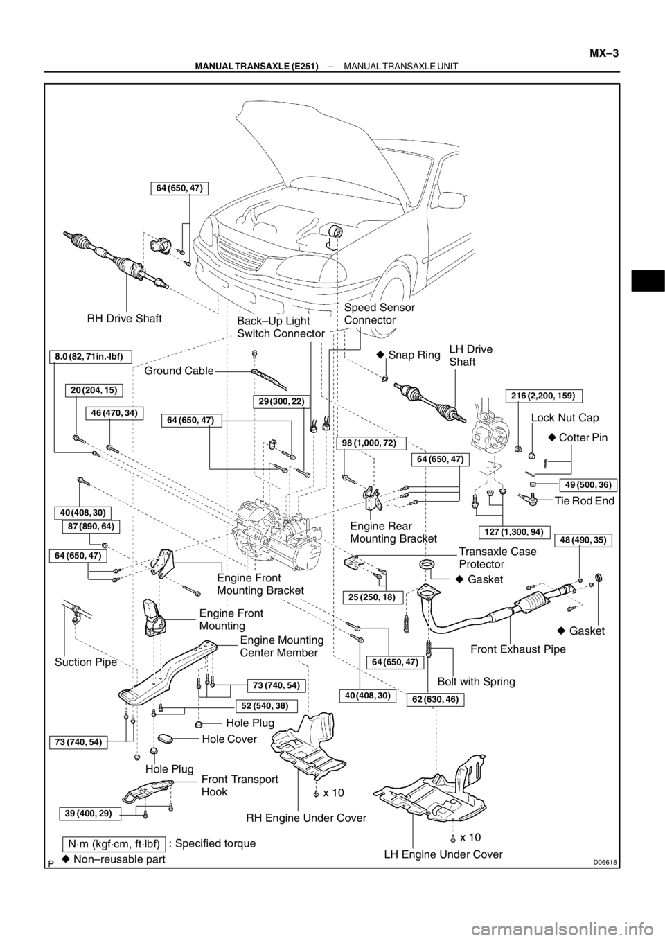
D06618
RH Drive Shaft
LH Drive
Shaft
216 (2,200, 159)
Lock Nut Cap
� Cotter Pin � Snap Ring
Front Exhaust Pipe
Engine Mounting
Center Member
LH Engine Under Cover RH Engine Under Cover
64 (650, 47)
Transaxle Case
Protector
25 (250, 18)
Back–Up Light
Switch Connector
Speed Sensor
Connector
Front Transport
HookHole Plug
Hole PlugHole Cover
64 (650, 47)
39 (400, 29)
73 (740, 54)
73 (740, 54)
52 (540, 38)
Tie Rod End
Engine Rear
Mounting Bracket
64 (650, 47)
98 (1,000, 72)
29 (300, 22)
64 (650, 47)
49 (500, 36)
127 (1,300, 94)
Ground Cable
Engine Front
Mounting Bracket
Engine Front
Mounting
Suction Pipe
N·m (kgf·cm, ft·lbf): Specified torque
� Non–reusable part� Gasket � Gasket
8.0 (82, 71in.·lbf)
40 (408, 30)
x 10Bolt with Spring
20 (204, 15)
46 (470, 34)
62 (630, 46)
48 (490, 35)
40 (408, 30)
87 (890, 64)
64 (650, 47)
x 10
– MANUAL TRANSAXLE (E251)MANUAL TRANSAXLE UNIT
MX–3
Page 132 of 349
MANUAL TRANSAXLE UNIT
MX–5
6. REMOVE STARTER
(a) Remove the 2 bolts and disconnect the radiator reservoir
from the radiator.
(b")
D06629
D06639
A
B
D06633
D06636
B AA
D06634
– MANUAL TRANSAXLE (E251)MANUAL TRANSAXLE UNIT
MX–5
6. REMOVE STARTER
(a) Remove the 2 bolts and disconnect the radiator reservoir
from the radiator.
(b) Disconnect the starter connector.
(c) Remove the nut, and disconnect the starter wire.
Torque: 15 N·m (153 kgf·cm, 11 ft·lbf)
(d) Remove the 2 bolts and starter.
Torque: 39 N·m (400 kgf·cm, 29 ft·lbf)
7. DISCONNECT CLUTCH RELEASE CYLINDER AND
LINE
(a) Remove the 2 set bolts of the clutch line bracket.
Torque:
Bolt A: 12 N·m (120 kgf·cm, 9 ft·lbf)
Bolt B: 4.9 N·m (50 kgf·cm, 43 in.·lbf)
(b) Remove the 2 bolts and disconnect the release cylinder
and line.
Torque: 12 N·m (120 kgf·cm, 9 ft·lbf)
8. DISCONNECT GROUND CABLE
Remove the set bolt of the ground cable from the transaxle.
9. DISCONNECT VEHICLE SPEED SENSOR AND
BACK–UP LIGHT SWITCH CONNECTORS
10. DISCONNECT CONTROL CABLE
(a) Remove the 2 clips and washers.
(b) Remove the 2 clips from the cables.
11. REMOVE 4 TRANSAXLE UPPER SIDE MOUNTING
BOLTS
Torque:
Bolt A: 64 N·m (650 kgf·cm, 47 ft·lbf)
Bolt B: 29 N·m (296 kgf·cm, 21 ft·lbf)
12. INSTALL ENGINE SUPPORT FIXTURE
Install the engine hanger in the correct direction.
Parts No.:
Engine hanger: 12281–27010
Bolt: 96122–61020
Torque: 37 N·m (377 kgf·cm, 27 ft·lbf)
Page 134 of 349
MANUAL TRANSAXLE UNIT
MX–7
(d) Remove the 2 hole plugs and hole cover.
(e) Remove the 7 bolts and center member.
Torque:
Bolt")
D06630
A
A
B
D02167
A
B
D06635
D06637
A
B
CED
– MANUAL TRANSAXLE (E251)MANUAL TRANSAXLE UNIT
MX–7
(d) Remove the 2 hole plugs and hole cover.
(e) Remove the 7 bolts and center member.
Torque:
Bolt A: 73 N·m (740 kgf·cm, 54 ft·lbf)
Bolt B: 52 N·m (540 kgf·cm, 38 ft·lbf)
21. JACK UP TRANSAXLE SLIGHTLY
Using a transmission jack, support the transaxle.
22. REMOVE ENGINE REAR MOUNTING BRACKET
Remove the 4 bolts and bracket.
Torque:
Bolt A: 98 N·m (1,000 kgf·cm, 72 ft·lbf)
Bolt B: 64 N·m (650 kgf·cm, 47 ft·lbf)
23. REMOVE ENGINE FRONT MOUNT AND MOUNTING
BRACKET
(a) Remove the bolt and nut.
Torque: 87 N·m (890 kgf·cm, 64 ft·lbf)
(b) Remove the 2 bolts.
Torque: 64 N·m (650 kgf·cm, 47 ft·lbf)
24. REMOVE TRANSAXLE LOWER SIDE MOUNTING
BOLT
Remove the 5 bolts.
Torque:
Bolt A: 40 N·m (408 kgf·cm, 30 ft·lbf)
Bolt B: 40 N·m (408 kgf·cm, 30 ft·lbf)
Bolt C: 8.0 N·m (82 kgf·cm, 71 in.·lbf)
Bolt D: 20 N·m (204 kgf·cm, 15 ft·lbf)
Bolt E: 46 N·m (470 kgf·cm, 34 ft·lbf)
25. REMOVE TRANSAXLE
Lower engine left side and remove the transaxle from the en-
gine.
HINT:
At the time of installation, please refer to the following items.
�Align the input shaft with the clutch disc and install the
transaxle to the engine.
�Temporarily tighten the transaxle mounting bolts.
26. REMOVE TRANSAXLE CASE PROTECTOR
Remove the 2 bolts and protector.
Torque: 25 N·m (250 kgf·cm, 18 ft·lbf)


Transmission case x Transaxle case
2930022
Transmission oil pipe x Transaxle case1717513
Reverse shift arm bracket assembly x Transaxle case171")
Steering Wheel Pad
(with Airbag)
Airbag Sensor Assembly Front Passenger
Airbag Assembly
Side Airbag Assembly
(LH)
Seat Belt
Pretensioner (LH)Side Air")