1999 SUZUKI GRAND VITARA Temperature
[x] Cancel search: TemperaturePage 447 of 656
7B1-38 AUTOMATIC TRANSMISSION (4 A/T)
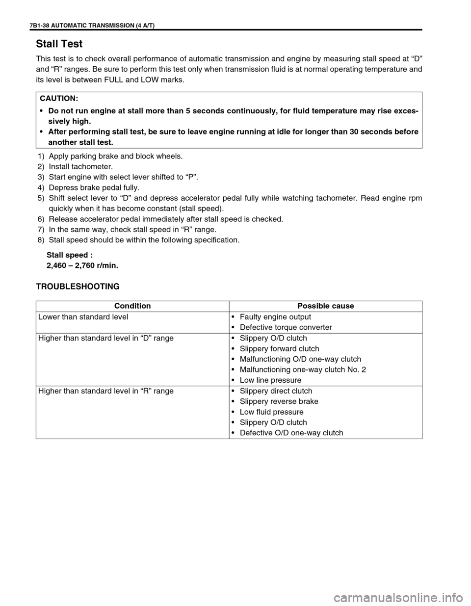
Stall Test
This test is to check overall performance of automatic transmission and engine by measuring stall speed at “D”
and “R” ranges. Be sure to perform this test only when transmission fluid is at normal operating temperature and
its level is between FULL and LOW marks.
1) Apply parking brake and block wheels.
2) Install tachometer.
3) Start engine with select lever shifted to “P”.
4) Depress brake pedal fully.
5) Shift select lever to “D” and depress accelerator pedal fully while watching tachometer. Read engine rpm
quickly when it has become constant (stall speed).
6) Release accelerator pedal immediately after stall speed is checked.
7) In the same way, check stall speed in “R” range.
8) Stall speed should be within the following specification.
Stall speed :
2,460 – 2,760 r/min.
TROUBLESHOOTING
CAUTION:
Do not run engine at stall more than 5 seconds continuously, for fluid temperature may rise exces-
sively high.
After performing stall test, be sure to leave engine running at idle for longer than 30 seconds before
another stall test.
Condition Possible cause
Lower than standard level•Faulty engine output
•Defective torque converter
Higher than standard level in “D” range•Slippery O/D clutch
•Slippery forward clutch
•Malfunctioning O/D one-way clutch
•Malfunctioning one-way clutch No. 2
•Low line pressure
Higher than standard level in “R” range•Slippery direct clutch
•Slippery reverse brake
•Low fluid pressure
•Slippery O/D clutch
•Defective O/D one-way clutch
Page 448 of 656
AUTOMATIC TRANSMISSION (4 A/T) 7B1-39
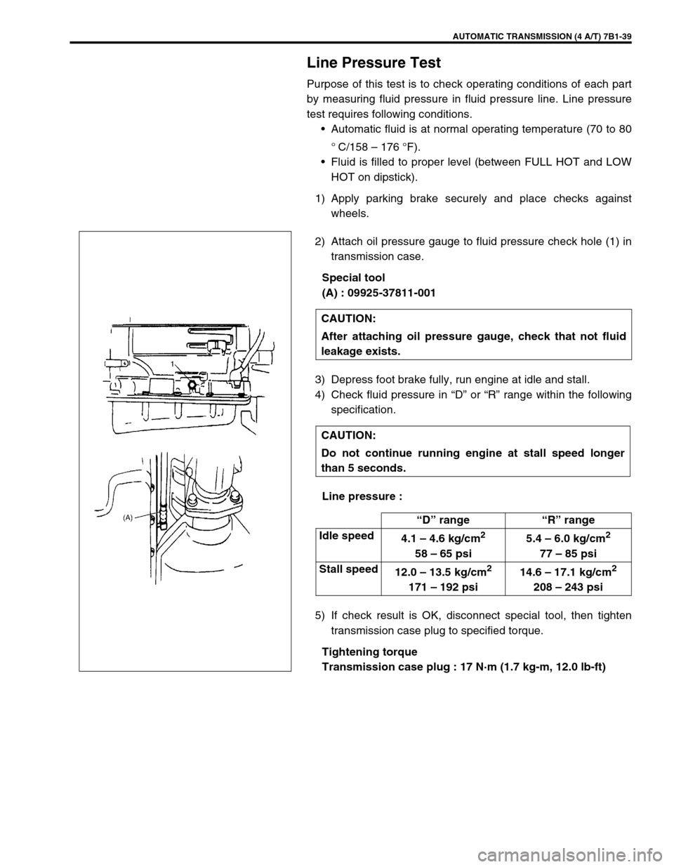
Line Pressure Test
Purpose of this test is to check operating conditions of each part
by measuring fluid pressure in fluid pressure line. Line pressure
test requires following conditions.
•Automatic fluid is at normal operating temperature (70 to 80
°
C/158 – 176 °F).
•Fluid is filled to proper level (between FULL HOT and LOW
HOT on dipstick).
1) Apply parking brake securely and place checks against
wheels.
2) Attach oil pressure gauge to fluid pressure check hole (1) in
transmission case.
Special tool
(A) : 09925-37811-001
3) Depress foot brake fully, run engine at idle and stall.
4) Check fluid pressure in “D” or “R” range within the following
specification.
Line pressure :
5) If check result is OK, disconnect special tool, then tighten
transmission case plug to specified torque.
Tightening torque
Transmission case plug : 17 N·m (1.7 kg-m, 12.0 lb-ft) CAUTION:
After attaching oil pressure gauge, check that not fluid
leakage exists.
CAUTION:
Do not continue running engine at stall speed longer
than 5 seconds.
“D” range“R” range
Idle speed
4.1 – 4.6 kg/cm
2
58 – 65 psi5.4 – 6.0 kg/cm
2
77 – 85 psi
Stall speed
12.0 – 13.5 kg/cm
2
171 – 192 psi14.6 – 17.1 kg/cm
2
208 – 243 psi
Page 452 of 656
AUTOMATIC TRANSMISSION (4 A/T) 7B1-43
On-Vehicle Service
Maintenance Service
Fluid level
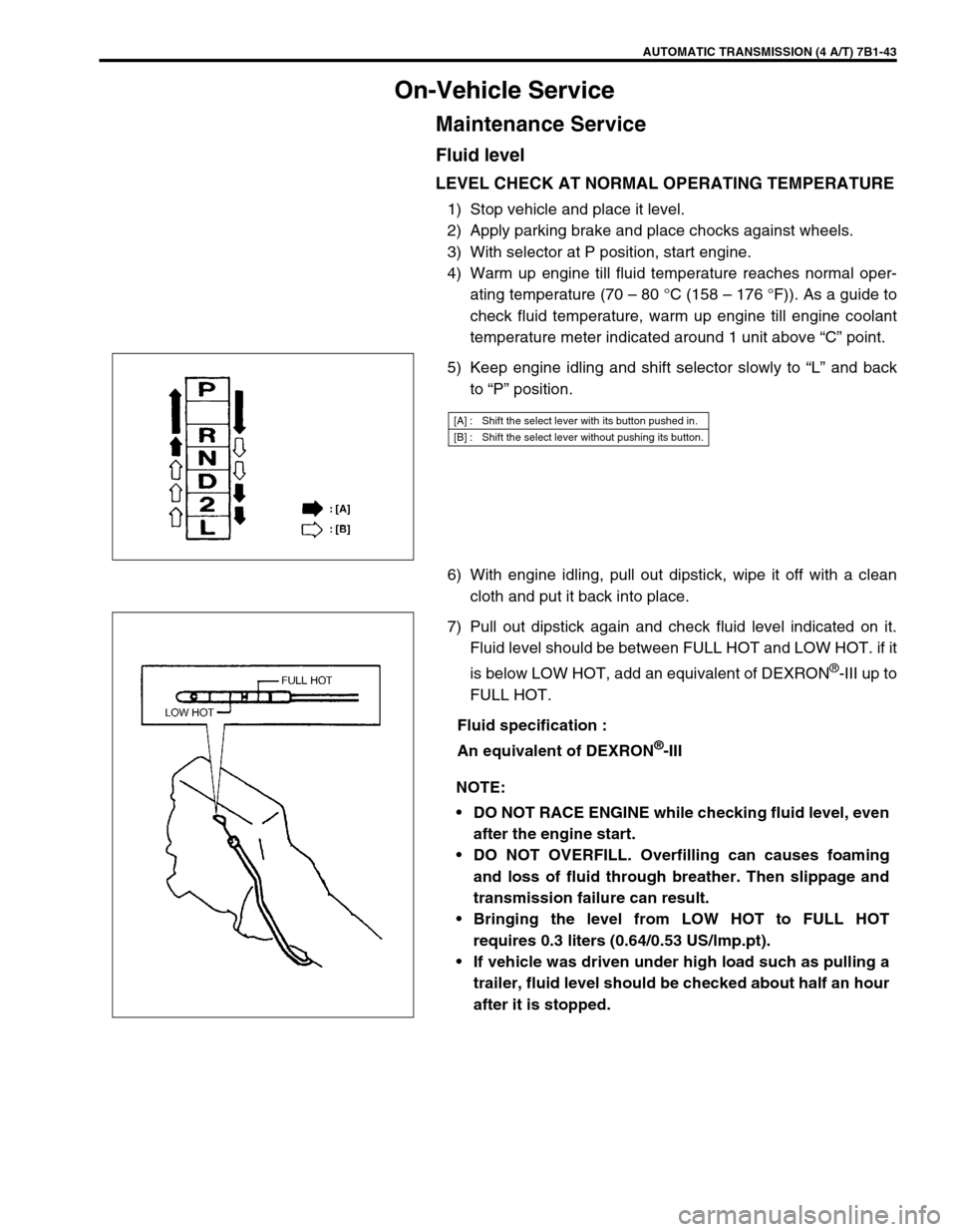
LEVEL CHECK AT NORMAL OPERATING TEMPERATURE
1) Stop vehicle and place it level.
2) Apply parking brake and place chocks against wheels.
3) With selector at P position, start engine.
4) Warm up engine till fluid temperature reaches normal oper-
ating temperature (70 – 80 °C (158 – 176 °F)). As a guide to
check fluid temperature, warm up engine till engine coolant
temperature meter indicated around 1 unit above “C” point.
5) Keep engine idling and shift selector slowly to “L” and back
to “P” position.
6) With engine idling, pull out dipstick, wipe it off with a clean
cloth and put it back into place.
7) Pull out dipstick again and check fluid level indicated on it.
Fluid level should be between FULL HOT and LOW HOT. if it
is below LOW HOT, add an equivalent of DEXRON
®-III up to
FULL HOT.
Fluid specification :
An equivalent of DEXRON
®-III
[A] : Shift the select lever with its button pushed in.
[B] : Shift the select lever without pushing its button.
NOTE:
DO NOT RACE ENGINE while checking fluid level, even
after the engine start.
DO NOT OVERFILL. Overfilling can causes foaming
and loss of fluid through breather. Then slippage and
transmission failure can result.
Bringing the level from LOW HOT to FULL HOT
requires 0.3 liters (0.64/0.53 US/lmp.pt).
If vehicle was driven under high load such as pulling a
trailer, fluid level should be checked about half an hour
after it is stopped.
Page 453 of 656
7B1-44 AUTOMATIC TRANSMISSION (4 A/T)
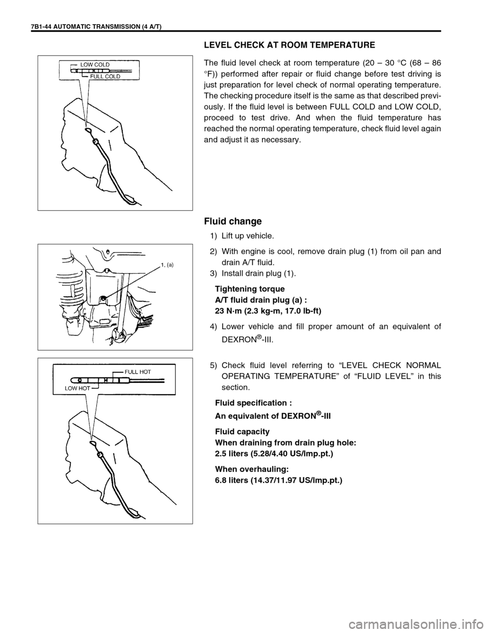
LEVEL CHECK AT ROOM TEMPERATURE
The fluid level check at room temperature (20 – 30 °C (68 – 86
°F)) performed after repair or fluid change before test driving is
just preparation for level check of normal operating temperature.
The checking procedure itself is the same as that described previ-
ously. If the fluid level is between FULL COLD and LOW COLD,
proceed to test drive. And when the fluid temperature has
reached the normal operating temperature, check fluid level again
and adjust it as necessary.
Fluid change
1) Lift up vehicle.
2) With engine is cool, remove drain plug (1) from oil pan and
drain A/T fluid.
3) Install drain plug (1).
Tightening torque
A/T fluid drain plug (a) :
23 N·m (2.3 kg-m, 17.0 lb-ft)
4) Lower vehicle and fill proper amount of an equivalent of
DEXRON
®-III.
5) Check fluid level referring to “LEVEL CHECK NORMAL
OPERATING TEMPERATURE” of “FLUID LEVEL” in this
section.
Fluid specification :
An equivalent of DEXRON
®-III
Fluid capacity
When draining from drain plug hole:
2.5 liters (5.28/4.40 US/lmp.pt.)
When overhauling:
6.8 liters (14.37/11.97 US/lmp.pt.)
Page 512 of 656

INSTRUMENTATION/DRIVER INFORMATION 8C-1
8C
SECTION 8C
INSTRUMENTATION/DRIVER INFORMATION
CONTENTS
General Description ........................................8C-2
Combination Meter ........................................8C-2
On-vehicle Service ..........................................8C-4
Fuel Meter/Fuel Gauge Unit ..........................8C-4
Fuel level sensor (sender gauge) ..............8C-4
Engine Coolant Temperature (ECT) Meter
and Sensor ....................................................8C-5Engine coolant temperature sensor .......... 8C-5
Oil Pressure Light ......................................... 8C-5
Oil pressure switch .................................... 8C-5
Brake Warning Light ..................................... 8C-5
Brake fluid level switch .............................. 8C-5
WARNING:
For vehicles equipped with Supplemental Restraint (Air Bag) System:
Service on and around the air bag system components or wiring must be performed only by an
authorized SUZUKI dealer. Refer to “Air Bag System Components and Wiring Location View” under
“General Description” in air bag system section in order to confirm whether you are performing ser-
vice on or near the air bag system components or wiring. Please observe all WARNINGS and “Ser-
vice Precautions” under “On-Vehicle Service” in air bag system section before performing service
on or around the air bag system components or wiring. Failure to follow WARNINGS could result in
unintentional activation of the system or could render the system inoperative. Either of these two
conditions may result in severe injury.
Technical service work must be started at least 90 seconds after the ignition switch is turned to the
“LOCK” position and the negative cable is disconnected from the battery. Otherwise, the system
may be activated by reserve energy in the Sensing and Diagnostic Module (SDM).
NOTE:
For the descriptions (items) not found in this section, refer to the same section of the Service Manual
mentioned in the FOREWORD of this manual.
Page 513 of 656
8C-2 INSTRUMENTATION/DRIVER INFORMATION
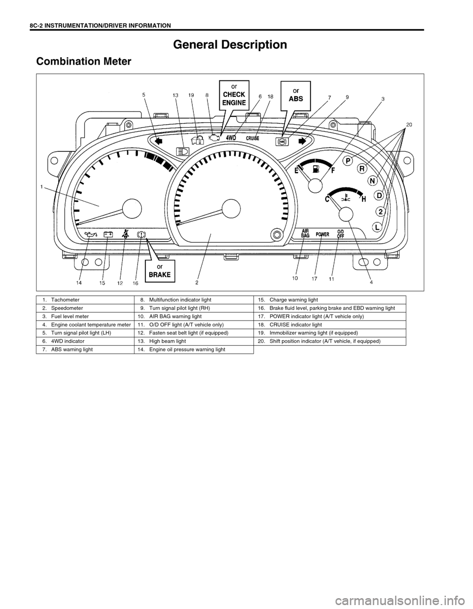
General Description
Combination Meter
1. Tachometer 8. Multifunction indicator light 15. Charge warning light
2. Speedometer 9. Turn signal pilot light (RH) 16. Brake fluid level, parking brake and EBD warning light
3. Fuel level meter 10. AIR BAG warning light 17. POWER indicator light (A/T vehicle only)
4. Engine coolant temperature meter 11. O/D OFF light (A/T vehicle only) 18. CRUISE indicator light
5. Turn signal pilot light (LH) 12. Fasten seat belt light (if equipped) 19. Immobilizer warning light (if equipped)
6. 4WD indicator 13. High beam light 20. Shift position indicator (A/T vehicle, if equipped)
7. ABS warning light 14. Engine oil pressure warning light
Page 516 of 656

INSTRUMENTATION/DRIVER INFORMATION 8C-5
Engine Coolant Temperature (ECT) Meter and
Sensor
Engine coolant temperature sensor
REMOVAL AND INSTALLATION
Refer to “ECT SENSOR” in Section 6E2.
Oil Pressure Light
Oil pressure switch
REMOVAL AND INSTALLATION
Refer to “OIL PRESSURE CHECK” in Section 6A2.
Brake Warning Light
Brake fluid level switch
INSPECTION
Use an ohmmeter to check switch for continuity.
If found defective, replace switch (reservoir).
Brake fluid level switch specification
OFF position (float up) : No continuity
ON position (float down) : Continuity
Page 626 of 656
AIR BAG SYSTEM 10B-49
On-Vehicle Service
Service Precautions
Service and diagnosis
WARNING/CAUTION labels are attached on each part of air bag system components (SDM, air bag (inflator)
modules and seat belt pretensioners). Be sure to follow the instructions.
•Many of service procedures require disconnection of “AIR BAG” fuse and air bag (inflator) module(s) (driver
and passenger) from initiator circuit to avoid an accidental deployment.
•Do not apply power to the air bag system unless all components are connected or a diagnostic chart
requests it, as this will set a diagnostic trouble code (DTC).
•The “AIR BAG DIAGNOSTIC SYSTEM CHECK” must be the starting point of any air bag diagnostics. The
“AIR BAG DIAGNOSTIC SYSTEM CHECK” will verify proper “AIR BAG” warning lamp operation and will
lead you to the correct table to diagnose any air bag malfunctions. Bypassing these procedures may result in
extended diagnostic time, incorrect diagnosis, and incorrect parts replacements.
•Never use air bag component parts from another vehicle.
•If the vehicle will be exposed to temperatures over 93°C (200°F) (for example, during a paint baking pro-
cess), remove the air bag system components beforehand to avoid component damage or unintended sys-
tem activation.
•When handling the air bag (inflator) modules (driver and passenger), seat belt pretensioners (driver and
passenger) or SDM, be careful not to drop it or apply an impact to it. If an excessive impact was applied
(e.g., SDM is dropped, air bag (inflator) module is dropped from a height of 90 cm (3 ft) or more, seat belt
pretensioner (retractor assembly) is dropped from a height of 30 cm (1 ft) or more), never attempt disassem-
bly or repair but replace it with a new one.
•When using electric welding, be sure to disconnect air bag (inflator) module connectors (driver and passen-
ger) and seat belt pretensioner connectors (driver and passenger) respectively.
•When applying paint around the air bag system related parts, use care so that the harness or connector will
not be exposed to the paint mist.
•Never expose air bag system component parts directly to hot air (drying or baking the vehicle after painting)
or flames. WARNING:
If the air bag system and another vehicle system both need repair, Suzuki recommends that the air
bag system be repaired first, to help avoid unintended air bag system activation.
Do not modify the steering wheel, dashboard or any other on or around air bag system compo-
nents. Modifications can adversely affect air bag system performance and lead to injury.
Failure to follow procedures could result in possible air bag system activation, personal injury or
unneeded air bag system repairs.
WARNING:
When performing service on or around air bag system components or air bag wiring, follow the proce-
dures listed in the following pages to temporarily disable the air bag system.
Failure to follow procedures could result in possible air bag system activation, personal injury or
unneeded air bag system repairs.