1999 SUZUKI GRAND VITARA Temperature
[x] Cancel search: TemperaturePage 55 of 656

1B-30 AIR CONDITIONING (OPTIONAL)
REMOVAL
1) Remove rear A/C unit referring to “REAR A/C UNIT” in this
section.
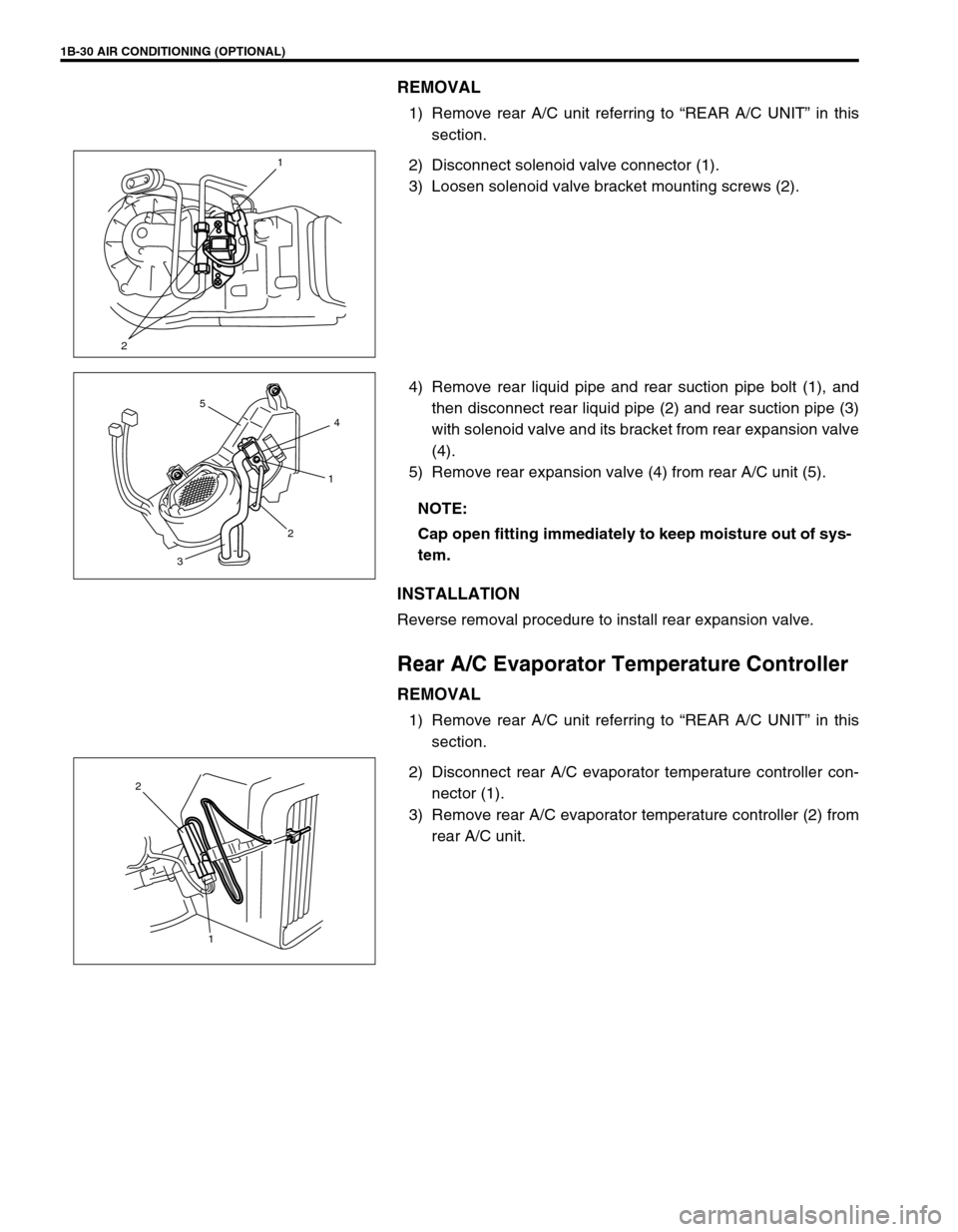
2) Disconnect solenoid valve connector (1).
3) Loosen solenoid valve bracket mounting screws (2).
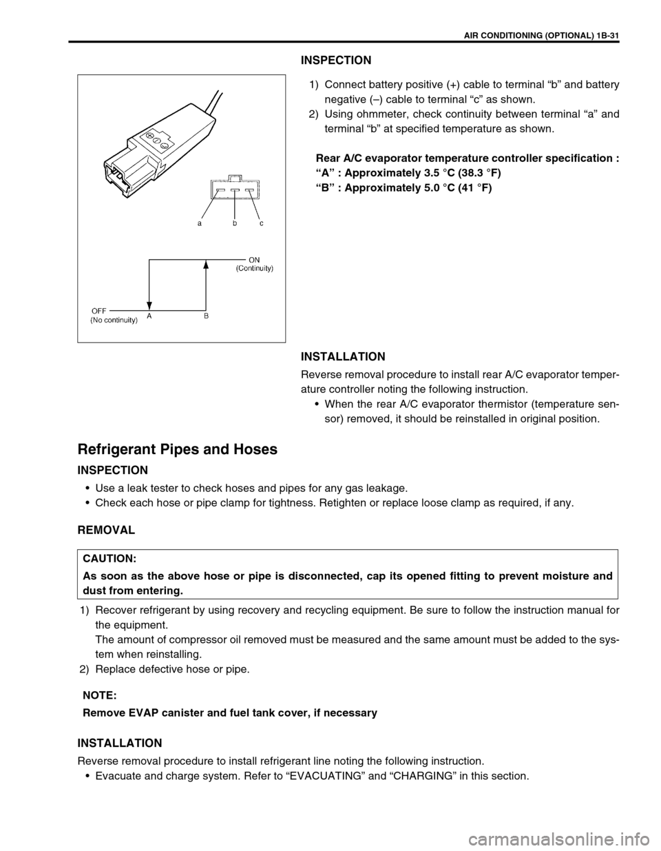
4) Remove rear liquid pipe and rear suction pipe bolt (1), and
then disconnect rear liquid pipe (2) and rear suction pipe (3)
with solenoid valve and its bracket from rear expansion valve
(4).
5) Remove rear expansion valve (4) from rear A/C unit (5).
INSTALLATION
Reverse removal procedure to install rear expansion valve.
Rear A/C Evaporator Temperature Controller
REMOVAL
1) Remove rear A/C unit referring to “REAR A/C UNIT” in this
section.
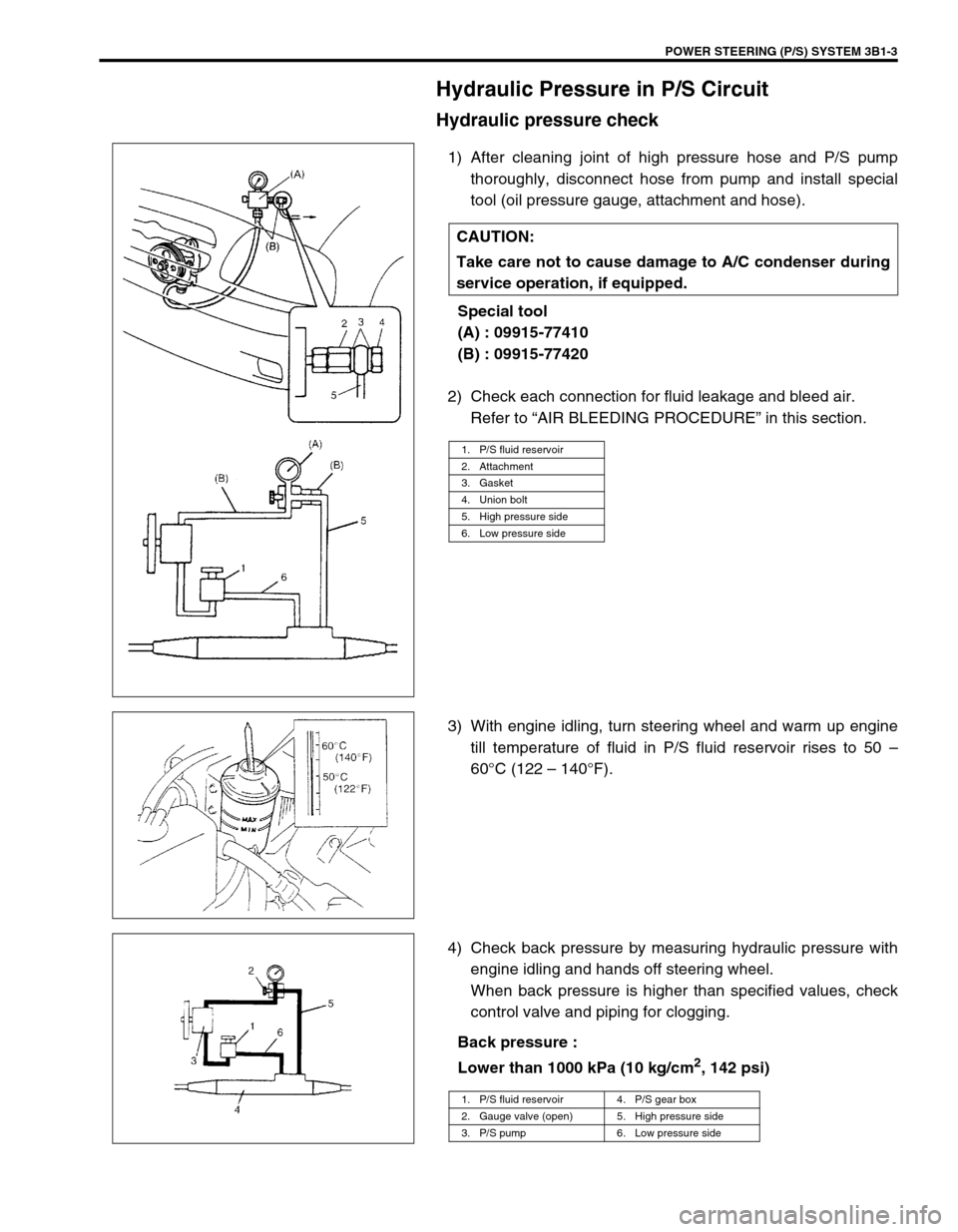
2) Disconnect rear A/C evaporator temperature controller con-
nector (1).
3) Remove rear A/C evaporator temperature controller (2) from
rear A/C unit.
21
NOTE:
Cap open fitting immediately to keep moisture out of sys-
tem.
4
1
2
3
5
1 2
Page 56 of 656

AIR CONDITIONING (OPTIONAL) 1B-31
INSPECTION
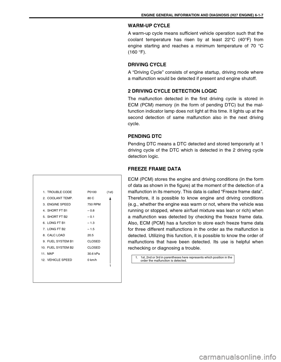
1) Connect battery positive (+) cable to terminal “b” and battery
negative (–) cable to terminal “c” as shown.
2) Using ohmmeter, check continuity between terminal “a” and
terminal “b” at specified temperature as shown.
Rear A/C evaporator temperature controller specification :
“A” : Approximately 3.5 °C (38.3 °F)
“B” : Approximately 5.0 °C (41 °F)
INSTALLATION
Reverse removal procedure to install rear A/C evaporator temper-
ature controller noting the following instruction.
When the rear A/C evaporator thermistor (temperature sen-
sor) removed, it should be reinstalled in original position.
Refrigerant Pipes and Hoses
INSPECTION
Use a leak tester to check hoses and pipes for any gas leakage.
Check each hose or pipe clamp for tightness. Retighten or replace loose clamp as required, if any.
REMOVAL
1) Recover refrigerant by using recovery and recycling equipment. Be sure to follow the instruction manual for
the equipment.
The amount of compressor oil removed must be measured and the same amount must be added to the sys-
tem when reinstalling.
2) Replace defective hose or pipe.
INSTALLATION
Reverse removal procedure to install refrigerant line noting the following instruction.
Evacuate and charge system. Refer to “EVACUATING” and “CHARGING” in this section.
CAUTION:
As soon as the above hose or pipe is disconnected, cap its opened fitting to prevent moisture and
dust from entering.
NOTE:
Remove EVAP canister and fuel tank cover, if necessary
Page 74 of 656

POWER STEERING (P/S) SYSTEM 3B1-3
Hydraulic Pressure in P/S Circuit
Hydraulic pressure check
1) After cleaning joint of high pressure hose and P/S pump
thoroughly, disconnect hose from pump and install special
tool (oil pressure gauge, attachment and hose).
Special tool
(A) : 09915-77410
(B) : 09915-77420
2) Check each connection for fluid leakage and bleed air.
Refer to “AIR BLEEDING PROCEDURE” in this section.
3) With engine idling, turn steering wheel and warm up engine
till temperature of fluid in P/S fluid reservoir rises to 50 –
60°C (122 – 140°F).
4) Check back pressure by measuring hydraulic pressure with
engine idling and hands off steering wheel.
When back pressure is higher than specified values, check
control valve and piping for clogging.
Back pressure :
Lower than 1000 kPa (10 kg/cm
2, 142 psi) CAUTION:
Take care not to cause damage to A/C condenser during
service operation, if equipped.
1. P/S fluid reservoir
2. Attachment
3. Gasket
4. Union bolt
5. High pressure side
6. Low pressure side
1. P/S fluid reservoir 4. P/S gear box
2. Gauge valve (open) 5. High pressure side
3. P/S pump 6. Low pressure side
Page 168 of 656

ENGINE GENERAL INFORMATION AND DIAGNOSIS (H27 ENGINE) 6-1-7
WARM-UP CYCLE
A warm-up cycle means sufficient vehicle operation such that the
coolant temperature has risen by at least 22°C (40°F) from
engine starting and reaches a minimum temperature of 70 °C
(160 °F).
DRIVING CYCLE
A “Driving Cycle” consists of engine startup, driving mode where
a malfunction would be detected if present and engine shutoff.
2 DRIVING CYCLE DETECTION LOGIC
The malfunction detected in the first driving cycle is stored in
ECM (PCM) memory (in the form of pending DTC) but the mal-
function indicator lamp does not light at this time. It lights up at the
second detection of same malfunction also in the next driving
cycle.
PENDING DTC
Pending DTC means a DTC detected and stored temporarily at 1
driving cycle of the DTC which is detected in the 2 driving cycle
detection logic.
FREEZE FRAME DATA
ECM (PCM) stores the engine and driving conditions (in the form
of data as shown in the figure) at the moment of the detection of a
malfunction in its memory. This data is called “Freeze frame data”.
Therefore, it is possible to know engine and driving conditions
(e.g., whether the engine was warm or not, where the vehicle was
running or stopped, where air/fuel mixture was lean or rich) when
a malfunction was detected by checking the freeze frame data.
Also, ECM (PCM) has a function to store each freeze frame data
for three different malfunctions in the order as the malfunction is
detected. Utilizing this function, it is possible to know the order of
malfunctions that have been detected. Its use is helpful when
rechecking or diagnosing a trouble.
1. 1st, 2nd or 3rd in parentheses here represents which position in the
order the malfunction is detected.
1. TROUBLE CODE
2. COOLANT TEMP.
3. ENGINE SPEED
4. SHORT FT B1
5. SHORT FT B2
6. LONG FT B1
7. LONG FT B2
8. CALC LOAD
9. FUEL SYSTEM B1
10. FUEL SYSTEM B2
11. MAP
12. VEHICLE SPEEDP0100
80 C
750 RPM
– 0.8
– 0.1
– 1.3
– 1.5
20.5
CLOSED
CLOSED
30.6 kPa
0 km/h(1st)
1
Page 179 of 656
![SUZUKI GRAND VITARA 1999 2.G Owners Manual 6-1-18 ENGINE GENERAL INFORMATION AND DIAGNOSIS (H27 ENGINE)
[Without using scan tool]
1) Turn the ignition switch OFF position.
2) Disconnect battery negative cable for specified time below to
erase SUZUKI GRAND VITARA 1999 2.G Owners Manual 6-1-18 ENGINE GENERAL INFORMATION AND DIAGNOSIS (H27 ENGINE)
[Without using scan tool]
1) Turn the ignition switch OFF position.
2) Disconnect battery negative cable for specified time below to
erase](/manual-img/20/7583/w960_7583-178.png)
6-1-18 ENGINE GENERAL INFORMATION AND DIAGNOSIS (H27 ENGINE)
[Without using scan tool]
1) Turn the ignition switch OFF position.
2) Disconnect battery negative cable for specified time below to
erase diagnostic trouble code stored in ECM memory and
reconnect it.
Time required to erase DTC:
Diagnostic Trouble Code (DTC) Table
Ambient
temperatureTime to cut power to ECM
Over 0°C (32°F) 30 sec. or longer
Under 0°C
(32°F)Not specifiable.
Select a place with higher than 0°C
(32°F) temperature.
DTC NO. DETECTED ITEMDETECTING CONDITION
(DTC will set when detecting : )MIL
(vehicle
without
monitor
connector)MIL
(vehicle
with
monitor
connector)
P0100
(No.34)
Mass air flow circuit malfunc-
tionSensor output too low
1 driving
cycle1 driving
cycle
P0100
(No.33)Sensor output too high
P0110
(No.25)
Intake air temp. circuit mal-
functionIntake air temp. circuit low input
1 driving
cycle1 driving
cycle
P0110
(No.23)Intake air temp. circuit high input
P0115
(No.15)
Engine coolant temp. circuit
malfunctionEngine coolant temp. circuit low input
1 driving
cycle1 driving
cycle
P0115
(No.14)Engine coolant temp. circuit high input
P0120
(No.22)
Throttle position circuit mal-
functionThrottle position circuit low input
1 driving
cycle1 driving
cycle
P0120
(No.21)Throttle position circuit high input
P0121Throttle position circuit perfor-
mance problemPoor performance of TP sensor2 driving
cyclesNot
applicable
*P0130HO2S circuit malfunction
(Bank 1 - Sensor 1)Min. output voltage of HO2S-1 is
higher than specification.
2 driving
cyclesNot
applicable Min. output voltage of HO2S-1 is
lower than specification.
Output voltage of HO2S-1 fails to go
above specification.
**P0130
(No.13)HO2S (Bank 1 - Sensor 1) no
activity detectedOutput voltage of HO2S-1 fails to go
above specification (or HO2S-1 cir-
cuit open).2 driving
cycles2 driving
cycles
Page 211 of 656

6-1-50 ENGINE GENERAL INFORMATION AND DIAGNOSIS (H27 ENGINE)
DTC P0110 (DTC No.23, 25) Intake Air Temp. (IAT) Circuit Malfunction
WIRING DIAGRAM
DTC DETECTING CONDITION AND TROUBLE AREA
DTC CONFIRMATION PROCEDURE
1) Connect scan tool to DLC with ignition switch OFF.
2) Turn ON ignition switch and clear DTC, pending DTC and freeze frame data by using scan tool and run
engine at idle speed and engine coolant temp. 110°C (230°F) or lower for 10 sec. or more.
3) Check DTC by using scan tool.
1. IAT sensor
2. ECM (PCM)
DTC DETECTING CONDITION TROUBLE AREA
Any one of the conditions are detected for 5 sec. con-
tinuously.
• Low intake air temperature (high voltage-high resis-
tance)
• High intake air temperature (Low voltage-low resis-
tance)• IAT sensor circuit
• IAT sensor
• ECM (PCM) malfunction
Page 213 of 656

6-1-52 ENGINE GENERAL INFORMATION AND DIAGNOSIS (H27 ENGINE)
DTC P0115 (DTC No.14, 15) Engine Coolant Temp. Circuit Malfunction
WIRING DIAGRAM
DTC DETECTING CONDITION AND TROUBLE AREA
DTC CONFIRMATION PROCEDURE
1) Connect scan tool to DLC with ignition switch OFF.
2) Turn ON ignition switch and clear DTC, pending DTC and freeze frame data by using scan tool and run
engine at idle speed for 10 sec. or more.
3) Check DTC by using scan tool.
1. ECT sensor
2. To combination (ECT) meter
3. ECM (PCM)
DTC DETECTING CONDITION TROUBLE AREA
Any one of the conditions are detected for 5 sec. continu-
ously.
• Low engine coolant temperature (high voltage-high
resistance)
• High engine coolant temperature (low voltage-low
resistance)ECT sensor circuit
ECT sensor
ECM (PCM)
NOTE:
Check to make sure that following conditions are satisfied when using this “DTC CONFIRMATION
PROCEDURE”.
Intake air temp. : – 8°C (18°F) or higher
Engine coolant temp. : – 8 – 110°C (18 – 230°F)
Altitude (barometric pressure) : 2400 m, 8000 ft or less (560 mmHg (75 kPa) or more)
Page 220 of 656

ENGINE GENERAL INFORMATION AND DIAGNOSIS (H27 ENGINE) 6-1-59
DTC CONFIRMATION PROCEDURE
1) Connect scan tool to DLC with ignition switch OFF.
2) Turn ON ignition switch and clear DTC, pending DTC and freeze frame data by using scan tool and start
engine.
3) Increase vehicle speed to 55 km/h (35 mph) or more.
4) Keep driving above vehicle speed for 2 min. or more (Change of vehicle speed is permitted in this step).
5) Stop vehicle, and run engine at idle speed for 1 min.
6) Check if pending DTC exists by using scan tool. If not, check if oxygen sensor monitoring test has completed
by using scan tool. If not in both of above checks (i.e., no pending DTC and oxygen sensor monitoring test
not completed), check vehicle condition (environmental) and repeat step 3) through 6).
TROUBLESHOOTING
WARNING:
When performing a road test, select a place where there is no traffic or possibility of a traffic acci-
dent and be very careful during testing to avoid occurrence of an accident.
Road test should be carried out with 2 persons, a driver and a tester, on a level road.
NOTE:
Check to make sure that following conditions are satisfied when using this “DTC CONFIRMATION
PROCEDURE”.
Intake air temp. : – 8°C (18°F) or higher
Engine coolant temp. : – 8 – 110°C (18 – 230°F)
Altitude (barometric pressure) : 2400 m, 8000 ft or less (560 mmHg (75 kPa) or more)
Step Action Yes No
1 Was “ENGINE DIAG. FLOW TABLE” performed? Go to Step 2. Go to “ENGINE
DIAG. FLOW
TABLE” in this sec-
tion.
2 HO2S-1 output voltage check :
1) Connect scan tool to DLC with ignition switch OFF.
2) Warm up engine to normal operating temperature and
keep it at 2000 r/min. for 60 sec.
3) Repeat racing engine (Repeat depressing accelerator
pedal 5 to 6 times continuously to enrich A/F mixture
and take foot off from pedal to enlean and check HO2S
output voltage displayed on scan tool. See Fig.
Is over 0.6 V and below 0.3 V indicated?Go to Step 4. Go to Step 3.
3 HO2S-1 check :
1) With ignition switch OFF, disconnect HO2S-1 connec-
tor.
2) Check for proper connection to HO2S-1 at each termi-
nal.
3) If OK, connect voltmeter “1” and “2” terminal of HO2S-1
connector.
4) Start engine and check voltmeter while repeating rac-
ing engine.
Is over 0.6 V and below 0.3 V indicated?“RED” or “GRY/
YEL” circuit open or
short.
If wire and connec-
tions are OK, sub-
stitute a known-
good ECM (PCM)
and recheck.Replace HO2S-1.