Page 348 of 656

ENGINE AND EMISSION CONTROL SYSTEM (SEQUENTIAL MULTIPORT FUEL INJECTION FOR H27 ENGINE) 6E2-15
Idle Speed/Idle Air Control (IAC) Duty Inspec-
tion
Before idle speed/IAC duty check, make sure of the following.
•Lead wires and hoses of engine/emission control systems
are connected securely.
•Accelerator cable is adjusted.
•Ignition timing is within specification.
•All accessories (wipers, heater, lights, A/C, etc.) are out of
service.
•Air cleaner has been properly installed and is in good condi-
tion.
•ECM (PCM) does not detect any malfunction DTC.
After above items are all confirmed, check idle speed and IAC
duty as follows.
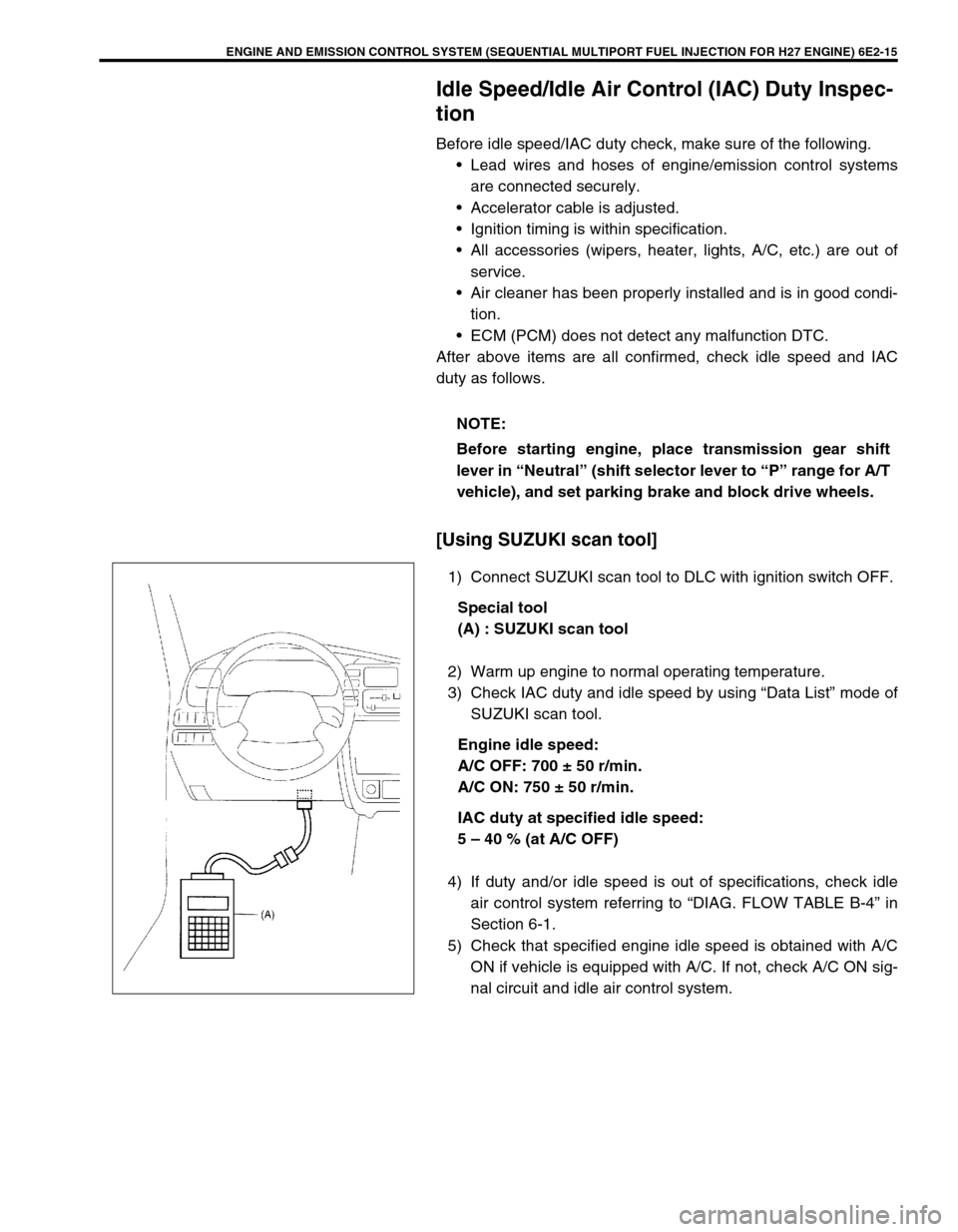
[Using SUZUKI scan tool]
1) Connect SUZUKI scan tool to DLC with ignition switch OFF.
Special tool
(A) : SUZUKI scan tool
2) Warm up engine to normal operating temperature.
3) Check IAC duty and idle speed by using “Data List” mode of
SUZUKI scan tool.
Engine idle speed:
A/C OFF: 700 ± 50 r/min.
A/C ON: 750 ± 50 r/min.
IAC duty at specified idle speed:
5 – 40 % (at A/C OFF)
4) If duty and/or idle speed is out of specifications, check idle
air control system referring to “DIAG. FLOW TABLE B-4” in
Section 6-1.
5) Check that specified engine idle speed is obtained with A/C
ON if vehicle is equipped with A/C. If not, check A/C ON sig-
nal circuit and idle air control system. NOTE:
Before starting engine, place transmission gear shift
lever in “Neutral” (shift selector lever to “P” range for A/T
vehicle), and set parking brake and block drive wheels.
Page 349 of 656
![SUZUKI GRAND VITARA 1999 2.G Owners Manual 6E2-16 ENGINE AND EMISSION CONTROL SYSTEM (SEQUENTIAL MULTIPORT FUEL INJECTION FOR H27 ENGINE)
[Not using SUZUKI scan tool] (vehicle with monitor
connector)
1) Disconnect scan tool from DLC if connec SUZUKI GRAND VITARA 1999 2.G Owners Manual 6E2-16 ENGINE AND EMISSION CONTROL SYSTEM (SEQUENTIAL MULTIPORT FUEL INJECTION FOR H27 ENGINE)
[Not using SUZUKI scan tool] (vehicle with monitor
connector)
1) Disconnect scan tool from DLC if connec](/manual-img/20/7583/w960_7583-348.png)
6E2-16 ENGINE AND EMISSION CONTROL SYSTEM (SEQUENTIAL MULTIPORT FUEL INJECTION FOR H27 ENGINE)
[Not using SUZUKI scan tool] (vehicle with monitor
connector)
1) Disconnect scan tool from DLC if connected.
2) Warm up engine to normal operating temperature.
3) Stop engine and connect duty meter (3) between duty output
terminal and ground terminal of monitor connector (1).
4) Using service wire (2), ground diagnosis switch terminal in
monitor connector.
5) Set tachometer.
6) Start engine and warm it up completely.
7) Check IAC duty and idle air control system referring to Diag-
nostic Flow Table B-4 “IDLE AIR CONTROL SYSTEM
CHECK” in this section.
•“OFF DUTY METER” is such duty meter that indicates
approx. 100% when terminal voltage is approx. “0 V”.
•“V
B” represents battery voltage while engine of vehicle being
checked is running.
8) Remove service wire from monitor connector.
9) Install cap to monitor connector.
10) Check that specified engine idle speed is obtained with A/C
ON if vehicle is equipped with A/C.
If not, check A/C ON signal circuit and idle air control sys-
tem.
A: Output duty select switch terminal
B: Diagnosis switch terminal
C: Blank
D: Ground terminal
E: Test switch terminal
F: Duty output terminal
A/C OFF A/C ON
Engine idle speed: 700 ± 50 r/min. 750 ± 50 r/min.
IAC duty at specified
idle speed:5 – 40 % (0.7 – 5.6 V
when battery voltage
is 14 V)–
NOTE:
IAC duty can be checked roughly by using voltmeter. I
AC duty to voltage relation is as follows.
ON DUTY METER
INDICATION
(%)OFF DUTY
INDICATION
(%)VOLT METER
INDICATION
(V)
0
50
10010
50
00
0.5 x V
B
VB
Page 367 of 656
6E2-34 ENGINE AND EMISSION CONTROL SYSTEM (SEQUENTIAL MULTIPORT FUEL INJECTION FOR H27 ENGINE)
Intake air temperature (IAT) sensor
REMOVAL
1) Disconnect negative (–) cable at battery.
2) Disconnect IAT sensor coupler.
3) Remove IAT sensor from air cleaner case.
INSPECTION
Immerse temperature sensing part of IAT sensor in water (or ice)
and measure resistance between sensor terminals while heating
water gradually.
If measured resistance doesn't show such characteristic as
shown in the figure, replace IAT sensor.
INSTALLATION
1) Clean mating surface of sensor and seal (2) on air cleaner
case.
2) Install IAT sensor (1) into seal.
3) Connect connector to IAT sensor securely.
Page 369 of 656
6E2-36 ENGINE AND EMISSION CONTROL SYSTEM (SEQUENTIAL MULTIPORT FUEL INJECTION FOR H27 ENGINE)
Engine coolant temperature sensor (ECT sensor)
REMOVAL
1) Disconnect negative (–) cable from battery.
2) Drain cooling system.
3) Disconnect coupler from ECT sensor (1).
4) Remove ECT sensor from water outlet cap (2).
INSPECTION
Immerse temperature sensing part of ECT sensor in water and
measure resistance between sensor terminals while heating
water gradually.
If measured resistance doesn’t shown such characteristic as
shown in the figure, replace ECT sensor.
INSTALLATION
Reverse removal procedure noting the followings.
•Clean mating surfaces of sensor and water outlet cap (1).
•Use new O-ring.
•Tighten ECT sensor to specified torque.
Tightening torque
ECT sensor (a) : 15 N·m (1.5 kg-m, 11.0 lb-ft)
•Connect coupler to sensor securely.
•Refill cooling system.
Page 371 of 656

6E2-38 ENGINE AND EMISSION CONTROL SYSTEM (SEQUENTIAL MULTIPORT FUEL INJECTION FOR H27 ENGINE)
HEATER INSPECTION
1) Disconnect HO2S-1 or -2 coupler.
2) Using ohmmeter, measure resistance between terminals
“VB” and “GND” of HO2S coupler (1).
If found faulty, replace HO2S.
Resistance of HO2S heater:
11.7 – 14.3 Ω
ΩΩ Ω (at 20 °C (68 °F)) for HO2S-2
5.0 – 6.4 Ω
ΩΩ Ω (at 20 °C (68 °F)) for HO2S-1
3) Connect HO2S coupler securely.
Heated oxygen sensor (sensor 2)
REMOVAL
1) Disconnect negative (–) cable from battery.
2) Disconnect coupler (3) of oxygen sensor(s).
3) Remove oxygen sensor(s) (2) from exhaust manifold(s) (1).
INSTALLATION
Reverse removal procedure noting the followings.
•Tighten oxygen sensor(s) to specified torque.
Tightening torque
Heated oxygen sensor 2 (a) : 45 N·m (4.5 kg-m, 32.5 lb-ft)
•Connect connector of oxygen sensor(s) and clamp wire har-
ness securely.
•After installing oxygen sensor(s), start engine and check that
no exhaust gas leakage exists. NOTE:
Temperature of HO2S affects resistance value largely.
Make sure that HO2S heater is at correct temperature.
WARNING:
To avoid danger of being burned, do not touch exhaust
system when system is hot. Oxygen sensor removal
should be performed when system is cool.
NOTE:
Be careful not to expose it to excessive shock.
Page 376 of 656
ENGINE AND EMISSION CONTROL SYSTEM (SEQUENTIAL MULTIPORT FUEL INJECTION FOR H27 ENGINE) 6E2-43
Fuel cut operation
INSPECTION
1) Warm up engine to normal operating temperature.
2) While listening to sound of injector by using sound scope (1)
or such, increase engine speed to higher than 3,000 r/min.
3) Check to make sure that sound to indicate operation of injec-
tor stops when throttle valve is closed instantly and it is
heard again when engine speed is reduced to less than
about 2,000 r/min. NOTE:
Before inspection, check to make sure that gear shift
lever is in Neutral position (with A/T model, selector lever
in “P” range) and that parking brake lever is pulled all the
way up.
Page 403 of 656

6H-6 CHARGING SYSTEM
Specifications
Battery
Generator
Tightening Torque Specification
Battery type 55D23L 75D23L 95D26L
Rated capacity AH/5HR, 12 Volts 48 52 66
Electrolyte L (US/Imp.pt) 3.9 (8.24/6.86) 3.9 (8.24/6.86) 4.0 (8.53/7.04)
Electrolyte S.G. 1.28 when fully charged at 20°C (68°F)
Type 105 A type
Rated voltage 12 V
Nominal output 105 A
Permissible max. speed 18000 r/min.
No-load speed 1150 r/min (rpm)
Setting voltage 14.2 to 14.8 V
Permissible ambient temperature–30 to 90 °C (–22 to 194 °F)
Polarity Negative ground
Rotation Clockwise viewed from pulley side
Fastening partTightening torque
Nm kg-m lb-ft
Body ground bolt 8 0.8 6.0
Generator mounting bolts and nut 23 2.3 16.5
“B” terminal inner nut 3.6 0.37 3.0
“B” terminal outer nut 8 0.8 6.0
Generator pulley nut 111 11.2 81.5
Rear end frame nuts 4.5 0.45 3.5
Rear end cover nuts 4.5 0.45 3.5
Stator stud bolts 9.8 1.0 7.0
Drive end bearing plate screws 3.0 0.30 2.2
Rectifier screws 3.0 0.30 2.2
Regulator and brush holder screws 2.0 0.20 1.5
Terminal plate bolt 3.9 0.39 3.0
Page 444 of 656

AUTOMATIC TRANSMISSION (4 A/T) 7B1-35
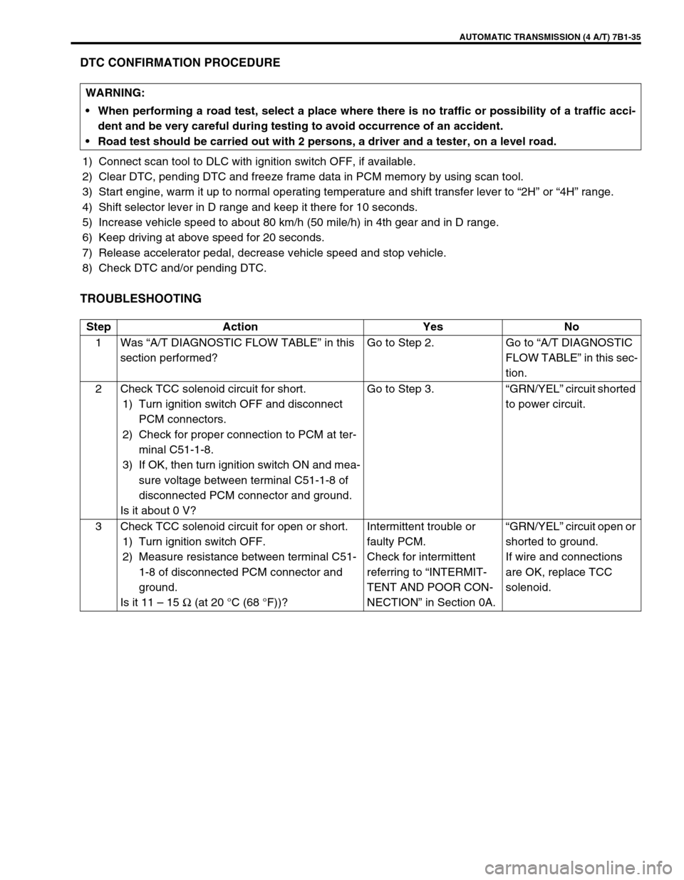
DTC CONFIRMATION PROCEDURE
1) Connect scan tool to DLC with ignition switch OFF, if available.
2) Clear DTC, pending DTC and freeze frame data in PCM memory by using scan tool.
3) Start engine, warm it up to normal operating temperature and shift transfer lever to “2H” or “4H” range.
4) Shift selector lever in D range and keep it there for 10 seconds.
5) Increase vehicle speed to about 80 km/h (50 mile/h) in 4th gear and in D range.
6) Keep driving at above speed for 20 seconds.
7) Release accelerator pedal, decrease vehicle speed and stop vehicle.
8) Check DTC and/or pending DTC.
TROUBLESHOOTING
WARNING:
When performing a road test, select a place where there is no traffic or possibility of a traffic acci-
dent and be very careful during testing to avoid occurrence of an accident.
Road test should be carried out with 2 persons, a driver and a tester, on a level road.
Step Action Yes No
1Was “A/T DIAGNOSTIC FLOW TABLE” in this
section performed?Go to Step 2. Go to “A/T DIAGNOSTIC
FLOW TABLE” in this sec-
tion.
2 Check TCC solenoid circuit for short.
1) Turn ignition switch OFF and disconnect
PCM connectors.
2) Check for proper connection to PCM at ter-
minal C51-1-8.
3) If OK, then turn ignition switch ON and mea-
sure voltage between terminal C51-1-8 of
disconnected PCM connector and ground.
Is it about 0 V?Go to Step 3.“GRN/YEL” circuit shorted
to power circuit.
3 Check TCC solenoid circuit for open or short.
1) Turn ignition switch OFF.
2) Measure resistance between terminal C51-
1-8 of disconnected PCM connector and
ground.
Is it 11 – 15 Ω (at 20 °C (68 °F))?Intermittent trouble or
faulty PCM.
Check for intermittent
referring to “INTERMIT-
TENT AND POOR CON-
NECTION” in Section 0A.“GRN/YEL” circuit open or
shorted to ground.
If wire and connections
are OK, replace TCC
solenoid.