1999 SUZUKI GRAND VITARA check engine
[x] Cancel search: check enginePage 18 of 656

MAINTENANCE AND LUBRICATION 0B-5
Maintenance Service
Engine and Emission Control
ITEM 1-1
Drive belt inspection and replacement
WATER PUMP AND GENERATOR DRIVE BELT INSPEC-
TION
1) Disconnect negative (–) cable at battery.
2) Inspect belt for cracks, cuts, deformation, wear and cleanli-
ness. If any defect exists, replace.
Check belt for tension.
Water pump and generator belt tension “a”: 9-11 mm
(0.35- 0.43 in.) deflection under 100 N, 10 kg or 22 lb pres-
sure
3) If belt is too tight or too loose, adjust it to specification by
adjusting alternator position.
4) Tighten alternator adjusting bolt and pivot bolts.
5) Connect negative (–) cable to battery.
WATER PUMP AND GENERATOR DRIVE BELT REPLACE-
MENT
Replace belt. Refer to Section 6B for replacement procedure of
pump belt.WARNING:
All inspection and replacement are to be performed with
ENGINE NOT RUNNING.
NOTE:
When replacing belt with a new one, adjust belt tension
to 7 - 9 mm (0.28 - 0.35 in.)
1. Crankshaft pulley
2. Water pump pulley
3. 100 N, 10 kg or 22 lb
Page 19 of 656
0B-6 MAINTENANCE AND LUBRICATION
POWER STEERING PUMP AND/OR A/C COMPRESSOR
DRIVE BELTS (IF EQUIPPED) INSPECTION
1) Disconnect negative (–) cable at battery.
2) Inspect belt for cracks, cuts, deformation, wear and cleanli-
ness. If any defect exists, replace.
Check belt for tension.
If belt tension is out of above specification, adjust it referring
to Section 1B or 3B1.
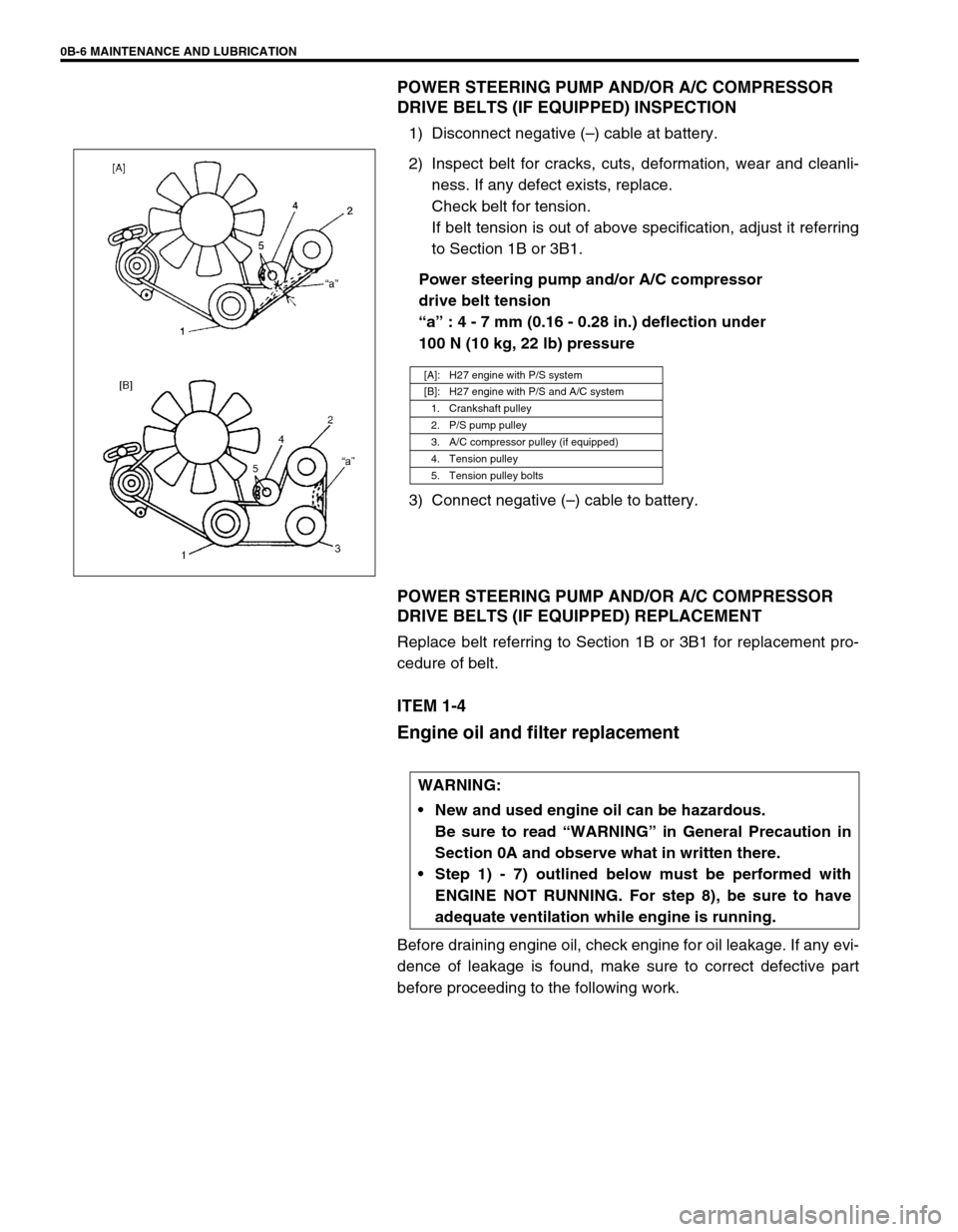
Power steering pump and/or A/C compressor
drive belt tension
“a” : 4 - 7 mm (0.16 - 0.28 in.) deflection under
100 N (10 kg, 22 lb) pressure
3) Connect negative (–) cable to battery.
POWER STEERING PUMP AND/OR A/C COMPRESSOR
DRIVE BELTS (IF EQUIPPED) REPLACEMENT
Replace belt referring to Section 1B or 3B1 for replacement pro-
cedure of belt.
ITEM 1-4
Engine oil and filter replacement
Before draining engine oil, check engine for oil leakage. If any evi-
dence of leakage is found, make sure to correct defective part
before proceeding to the following work.
[A]: H27 engine with P/S system
[B]: H27 engine with P/S and A/C system
1. Crankshaft pulley
2. P/S pump pulley
3. A/C compressor pulley (if equipped)
4. Tension pulley
5. Tension pulley bolts
WARNING:
New and used engine oil can be hazardous.
Be sure to read “WARNING” in General Precaution in
Section 0A and observe what in written there.
Step 1) - 7) outlined below must be performed with
ENGINE NOT RUNNING. For step 8), be sure to have
adequate ventilation while engine is running.
Page 21 of 656
0B-8 MAINTENANCE AND LUBRICATION
6) Replenish oil until oil level is brought to FULL level mark on
dipstick. (oil pan and oil filter capacity). The filler inlet is at
the top of the cylinder head cover.
It is recommended to use engine oil of SE, SF, SG, SH or SJ
grade.
NOTE:
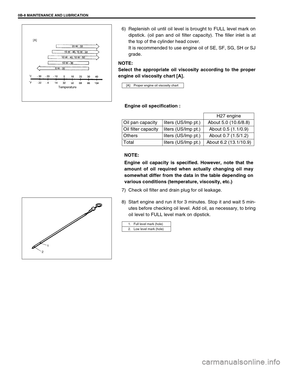
Select the appropriate oil viscosity according to the proper
engine oil viscosity chart [A].
Engine oil specification :
7) Check oil filter and drain plug for oil leakage.
8) Start engine and run it for 3 minutes. Stop it and wait 5 min-
utes before checking oil level. Add oil, as necessary, to bring
oil level to FULL level mark on dipstick.
[A]: Proper engine oil viscosity chart
H27 engine
Oil pan capacity liters (US/lmp pt.) About 5.0 (10.6/8.8)
Oil filter capacity liters (US/lmp pt.) About 0.5 (1.1/0.9)
Others liters (US/lmp pt.) About 0.7 (1.5/1.2)
Total liters (US/lmp pt.) About 6.2 (13.1/10.9)
NOTE:
Engine oil capacity is specified. However, note that the
amount of oil required when actually changing oil may
somewhat differ from the data in the table depending on
various conditions (temperature, viscosity, etc.)
1. Full level mark (hole)
2. Low level mark (hole)
Page 34 of 656
AIR CONDITIONING (OPTIONAL) 1B-9
Quickly Checking of Refrigerant Charge (If
Equipped with Sight Glass)
The following procedure can be used for quickly checking whether
the A/C system has a proper charge of refrigerant or not.
1) Run engine at fast idle.
2) Operate A/C at the following conditions for a few minutes.
Main (front) A/C switch at ON position.
Rear A/C main switch at ON position (if equipped).
Front blower motor switch at max position.
Rear blower motor switch at max position (if equipped).
Air outlet control button at face position.
Temperature control lever at max cool position.
Vehicle door at all open.
Air inlet door at recirculation position.
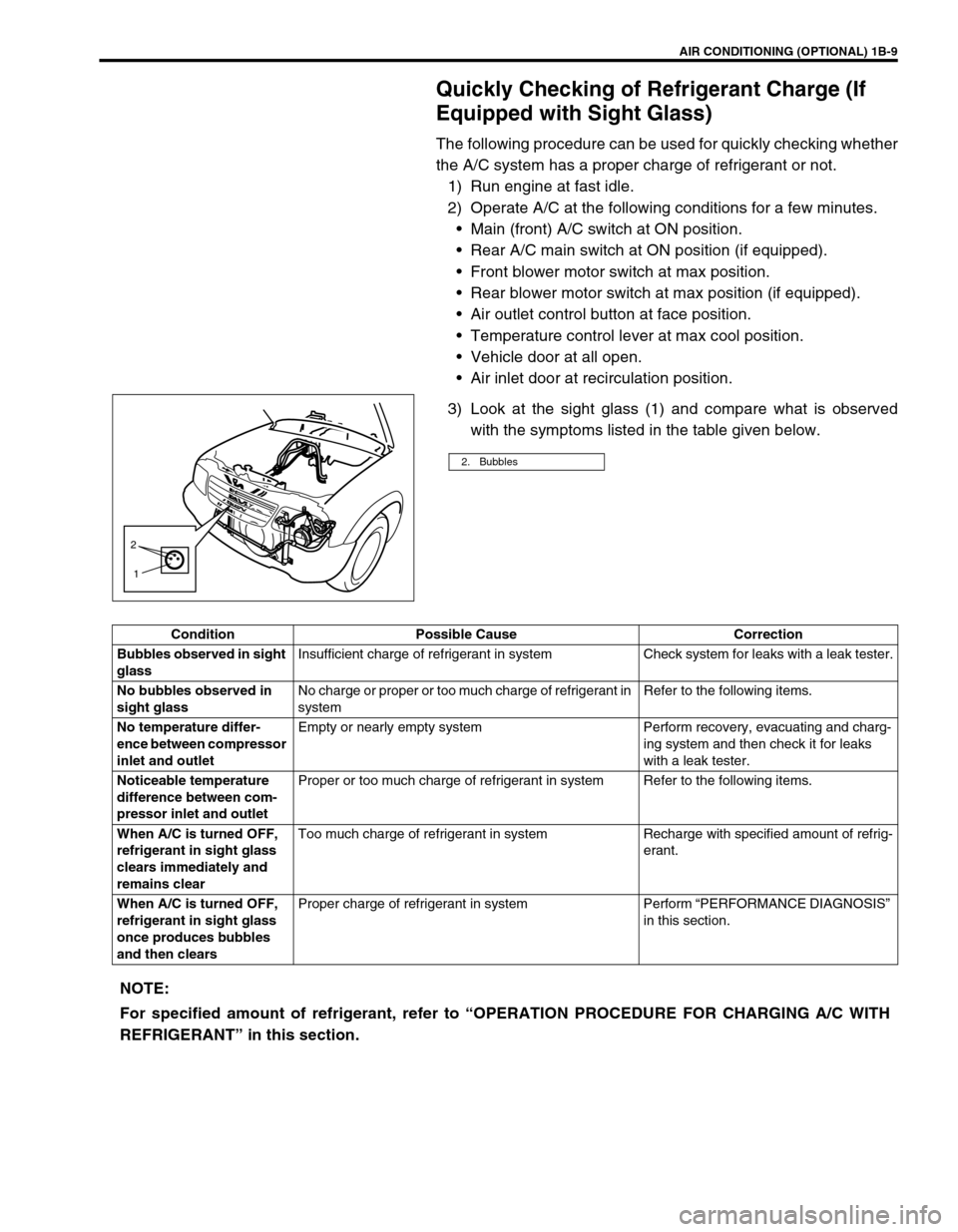
3) Look at the sight glass (1) and compare what is observed
with the symptoms listed in the table given below.
2. Bubbles
2
1
Condition Possible Cause Correction
Bubbles observed in sight
glassInsufficient charge of refrigerant in system Check system for leaks with a leak tester.
No bubbles observed in
sight glassNo charge or proper or too much charge of refrigerant in
systemRefer to the following items.
No temperature differ-
ence between compressor
inlet and outletEmpty or nearly empty system Perform recovery, evacuating and charg-
ing system and then check it for leaks
with a leak tester.
Noticeable temperature
difference between com-
pressor inlet and outletProper or too much charge of refrigerant in system Refer to the following items.
When A/C is turned OFF,
refrigerant in sight glass
clears immediately and
remains clearToo much charge of refrigerant in system Recharge with specified amount of refrig-
erant.
When A/C is turned OFF,
refrigerant in sight glass
once produces bubbles
and then clearsProper charge of refrigerant in system Perform “PERFORMANCE DIAGNOSIS”
in this section.
NOTE:
For specified amount of refrigerant, refer to “OPERATION PROCEDURE FOR CHARGING A/C WITH
REFRIGERANT” in this section.
Page 37 of 656
1B-12 AIR CONDITIONING (OPTIONAL)
Performance diagnosis table
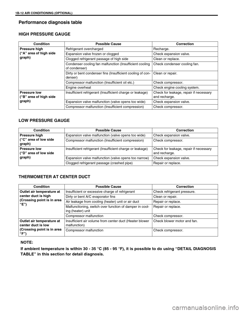
HIGH PRESSURE GAUGE
LOW PRESSURE GAUGE
THERMOMETER AT CENTER DUCT
Condition Possible Cause Correction
Pressure high
(“A” area of high side
graph)Refrigerant overcharged Recharge.
Expansion valve frozen or clogged Check expansion valve.
Clogged refrigerant passage of high side Clean or replace.
Condenser cooling fan malfunction (Insufficient cooling
of condenser)Check condenser cooling fan.
Dirty or bent condenser fins (Insufficient cooling of con-
denser)Clean or repair.
Compressor malfunction (Insufficient oil etc.) Check compressor.
Engine overheat Check engine cooling system.
Pressure low
(“B” area of high side
graph)Insufficient refrigerant (Insufficient charge or leakage) Check for leakage, repair if necessary
and recharge.
Expansion valve malfunction (valve opens too wide) Check expansion valve.
Compressor malfunction (Insufficient compression) Check compressor.
Condition Possible Cause Correction
Pressure high
(“C” area of low side
graph)Expansion valve malfunction (valve opens too wide) Check expansion valve.
Compressor malfunction (Insufficient compression) Check compressor.
Pressure low
(“D” area of low side
graph)Insufficient refrigerant (Insufficient charge or leakage) Check for leakage, repair if necessary
and recharge.
Expansion valve malfunction (valve opens too narrow) Check expansion valve.
Clogged refrigerant passage (crashed pipe) Repair or replace.
Condition Possible Cause Correction
Outlet air temperature at
center duct is high
(Crossing point is in area
“E”)Insufficient or excessive charge of refrigerant Check refrigerant pressure.
Dirty or bent A/C evaporator fins Clean or repair.
Air leakage from cooling (heater) unit or air duct Repair or replace.
Malfunctioning, switch over function of damper in cool-
ing (heater) unitRepair or replace.
Compressor malfunction Check compressor.
Outlet air temperature at
center duct is low
(Crossing point is in area
“F”)Insufficient air volume from center duct (Heater blower
malfunction)Check blower motor and fan.
Compressor malfunction Check compressor.
NOTE:
If ambient temperature is within 30 - 35 °C (85 - 95 °F), it is possible to do using “DETAIL DIAGNOSIS
TABLE” in this section for detail diagnosis.
Page 38 of 656
AIR CONDITIONING (OPTIONAL) 1B-13
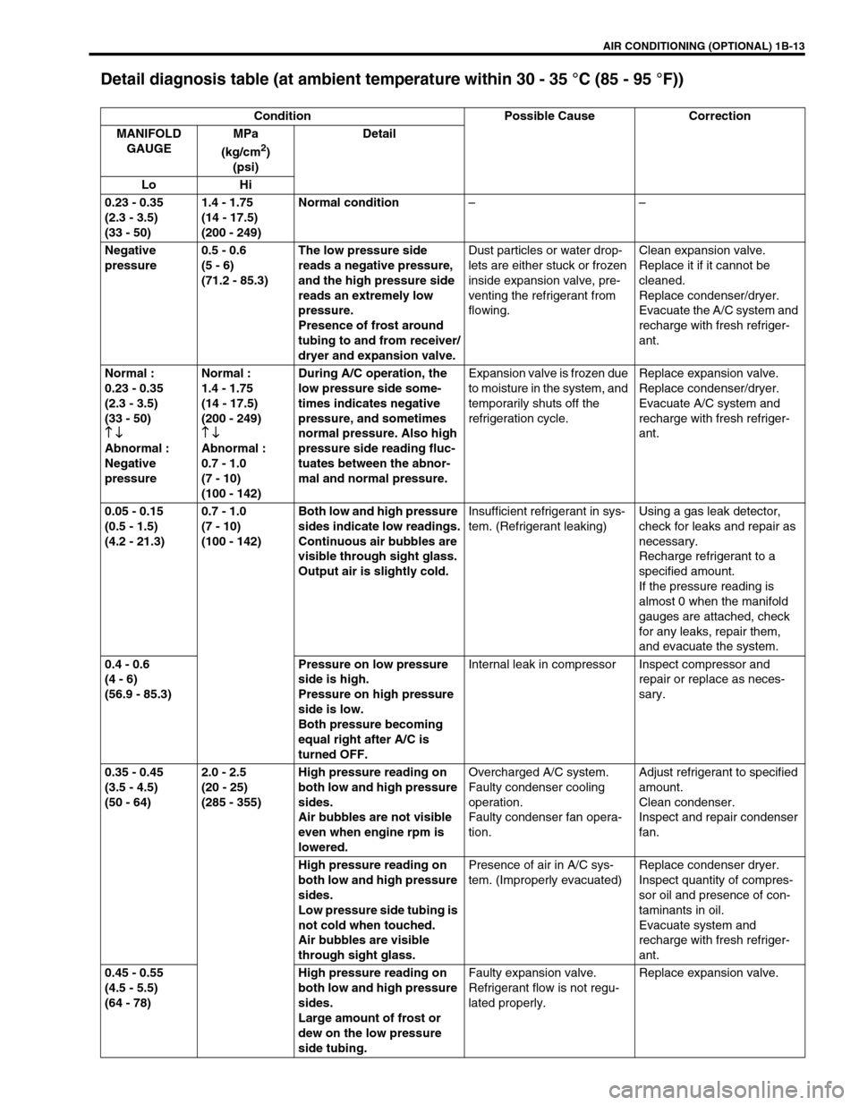
Detail diagnosis table (at ambient temperature within 30 - 35 °C (85 - 95 °F))
Condition Possible Cause Correction
MANIFOLD
GAUGEMPa
(kg/cm
2)
(psi)Detail
Lo Hi
0.23 - 0.35
(2.3 - 3.5)
(33 - 50)1.4 - 1.75
(14 - 17.5)
(200 - 249)Normal condition––
Negative
pressure0.5 - 0.6
(5 - 6)
(71.2 - 85.3)The low pressure side
reads a negative pressure,
and the high pressure side
reads an extremely low
pressure.
Presence of frost around
tubing to and from receiver/
dryer and expansion valve.Dust particles or water drop-
lets are either stuck or frozen
inside expansion valve, pre-
venting the refrigerant from
flowing.Clean expansion valve.
Replace it if it cannot be
cleaned.
Replace condenser/dryer.
Evacuate the A/C system and
recharge with fresh refriger-
ant.
Normal :
0.23 - 0.35
(2.3 - 3.5)
(33 - 50)
↑ ↓
↑ ↓↑ ↓ ↑ ↓
Abnormal :
Negative
pressureNormal :
1.4 - 1.75
(14 - 17.5)
(200 - 249)
↑ ↓
↑ ↓↑ ↓ ↑ ↓
Abnormal :
0.7 - 1.0
(7 - 10)
(100 - 142)During A/C operation, the
low pressure side some-
times indicates negative
pressure, and sometimes
normal pressure. Also high
pressure side reading fluc-
tuates between the abnor-
mal and normal pressure.Expansion valve is frozen due
to moisture in the system, and
temporarily shuts off the
refrigeration cycle.Replace expansion valve.
Replace condenser/dryer.
Evacuate A/C system and
recharge with fresh refriger-
ant.
0.05 - 0.15
(0.5 - 1.5)
(4.2 - 21.3)0.7 - 1.0
(7 - 10)
(100 - 142)Both low and high pressure
sides indicate low readings.
Continuous air bubbles are
visible through sight glass.
Output air is slightly cold.Insufficient refrigerant in sys-
tem. (Refrigerant leaking)Using a gas leak detector,
check for leaks and repair as
necessary.
Recharge refrigerant to a
specified amount.
If the pressure reading is
almost 0 when the manifold
gauges are attached, check
for any leaks, repair them,
and evacuate the system.
0.4 - 0.6
(4 - 6)
(56.9 - 85.3)Pressure on low pressure
side is high.
Pressure on high pressure
side is low.
Both pressure becoming
equal right after A/C is
turned OFF.Internal leak in compressor Inspect compressor and
repair or replace as neces-
sary.
0.35 - 0.45
(3.5 - 4.5)
(50 - 64)2.0 - 2.5
(20 - 25)
(285 - 355)High pressure reading on
both low and high pressure
sides.
Air bubbles are not visible
even when engine rpm is
lowered.Overcharged A/C system.
Faulty condenser cooling
operation.
Faulty condenser fan opera-
tion.Adjust refrigerant to specified
amount.
Clean condenser.
Inspect and repair condenser
fan.
High pressure reading on
both low and high pressure
sides.
Low pressure side tubing is
not cold when touched.
Air bubbles are visible
through sight glass.Presence of air in A/C sys-
tem. (Improperly evacuated)Replace condenser dryer.
Inspect quantity of compres-
sor oil and presence of con-
taminants in oil.
Evacuate system and
recharge with fresh refriger-
ant.
0.45 - 0.55
(4.5 - 5.5)
(64 - 78)High pressure reading on
both low and high pressure
sides.
Large amount of frost or
dew on the low pressure
side tubing.Faulty expansion valve.
Refrigerant flow is not regu-
lated properly.Replace expansion valve.
Page 47 of 656
1B-22 AIR CONDITIONING (OPTIONAL)
Checking system for pressure leaks
After completing the evacuation, close manifold gauge high pres-
sure valve (HI) and low-pressure valve (LO) and wait 10 minutes.
Verify that low-pressure gauge reading has not changed.
Charging
CAUTION:
If the gauge reading moves closer to “0”, there is a leak
somewhere. Inspect the tubing connections, make nec-
essary corrections, and evacuate system once again,
making sure that there are no leaks.
CAUTION:
ALWAYS CHARGE THROUGH LOW PRESSURE-SIDE of A/C system at after the initial charging is
performed from the high-pressure side with the engine stopped.
NEVER CHARGE TO HIGH PRESSURE-SIDE of A/C system with engine running.
Do not charge while compressor is hot.
When installing tap valve to refrigerant container to make a hole there through, carefully follow
directions given by manufacturer.
A pressure gauge should always be used before and during charging.
The refrigerant container should be emptied of refrigerant when discarding it.
The refrigerant container should not be heated up to 40 °C (104 °F) or over.
Refrigerant container should not be reversed in direction during charging. Reversing in direction
causes liquid refrigerant to enter compressor, causing troubles, such as compression of liquid
refrigerant and the like.
NOTE:
The air conditioning system contains HFC-134a (R-134a).
Described here is a method to charge the air conditioning system with refrigerant from the refrigerant
service container.
When charging refrigerant recovered by using the refrigerant and recycling equipment (when recy-
cling refrigerant), follow the procedure described in the equipment manufacturer’s instruction manual.
Page 48 of 656
AIR CONDITIONING (OPTIONAL) 1B-23
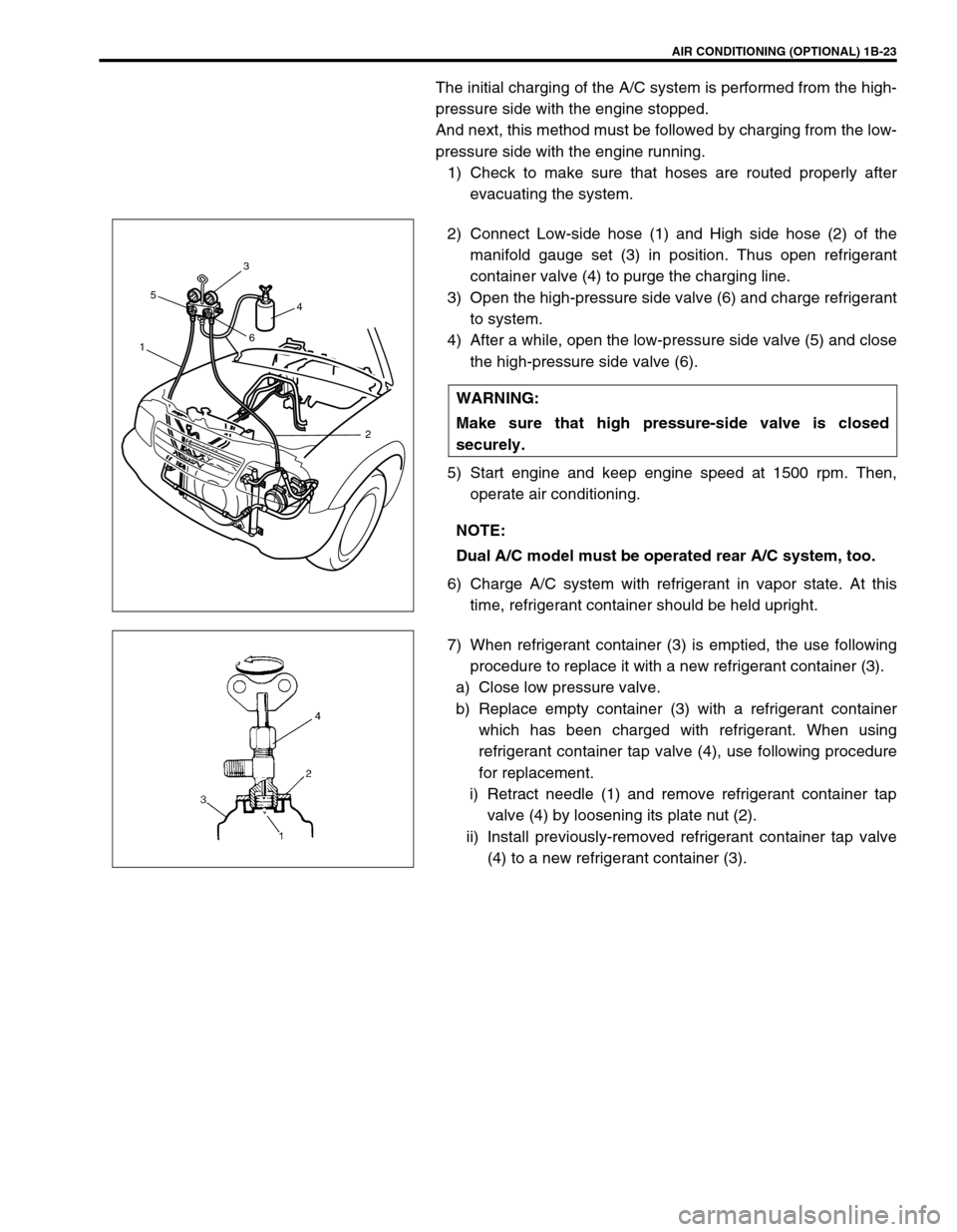
The initial charging of the A/C system is performed from the high-
pressure side with the engine stopped.
And next, this method must be followed by charging from the low-
pressure side with the engine running.
1) Check to make sure that hoses are routed properly after
evacuating the system.
2) Connect Low-side hose (1) and High side hose (2) of the
manifold gauge set (3) in position. Thus open refrigerant
container valve (4) to purge the charging line.
3) Open the high-pressure side valve (6) and charge refrigerant
to system.
4) After a while, open the low-pressure side valve (5) and close
the high-pressure side valve (6).
5) Start engine and keep engine speed at 1500 rpm. Then,
operate air conditioning.
6) Charge A/C system with refrigerant in vapor state. At this
time, refrigerant container should be held upright.
7) When refrigerant container (3) is emptied, the use following
procedure to replace it with a new refrigerant container (3).
a) Close low pressure valve.
b) Replace empty container (3) with a refrigerant container
which has been charged with refrigerant. When using
refrigerant container tap valve (4), use following procedure
for replacement.
i) Retract needle (1) and remove refrigerant container tap
valve (4) by loosening its plate nut (2).
ii) Install previously-removed refrigerant container tap valve
(4) to a new refrigerant container (3). WARNING:
Make sure that high pressure-side valve is closed
securely.
NOTE:
Dual A/C model must be operated rear A/C system, too.
153
64
2