1999 SUZUKI GRAND VITARA Battery connection
[x] Cancel search: Battery connectionPage 150 of 656

ANTILOCK BRAKE SYSTEM (ABS) 5E2-25
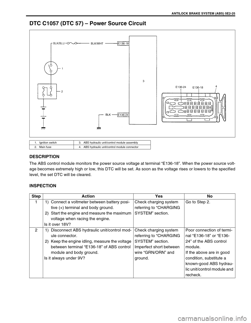
DTC C1057 (DTC 57) – Power Source Circuit
DESCRIPTION
The ABS control module monitors the power source voltage at terminal “E136-18”. When the power source volt-
age becomes extremely high or low, this DTC will be set. As soon as the voltage rises or lowers to the specified
level, the set DTC will be cleared.
INSPECTION
1. Ignition switch 3. ABS hydraulic unit/control module assembly
2. Main fuse 4. ABS hydraulic unit/control module connector
Step Action Yes No
1 1) Connect a voltmeter between battery posi-
tive (+) terminal and body ground.
2) Start the engine and measure the maximum
voltage when racing the engine.
Is it over 18V?Check charging system
referring to “CHARGING
SYSTEM” section.Go to Step 2.
2 1) Disconnect ABS hydraulic unit/control mod-
ule connector.
2) Keep the engine idling, measure the voltage
between terminal “E136-18” of ABS control
module and body ground.
Is it always under 9V?Check charging system
referring to “CHARGING
SYSTEM” section.
Imperfect short between
wire “GRN/ORN” and
ground.Poor connection of termi-
nal “E136-18” or “E136-
24” of the ABS control
module.
If the above are in good
condition, substitute a
known-good ABS hydrau-
lic unit/control module and
recheck.
Page 152 of 656

ANTILOCK BRAKE SYSTEM (ABS) 5E2-27
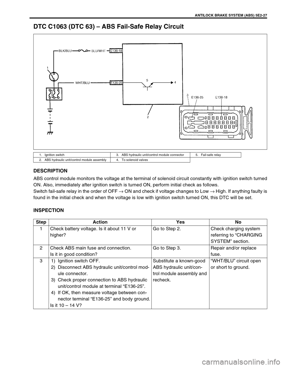
DTC C1063 (DTC 63) – ABS Fail-Safe Relay Circuit
DESCRIPTION
ABS control module monitors the voltage at the terminal of solenoid circuit constantly with ignition switch turned
ON. Also, immediately after ignition switch is turned ON, perform initial check as follows.
Switch fail-safe relay in the order of OFF → ON and check if voltage changes to Low → High. If anything faulty is
found in the initial check and when the voltage is low with ignition switch turned ON, this DTC will be set.
INSPECTION
1. Ignition switch 3. ABS hydraulic unit/control module connector 5. Fail-safe relay
2. ABS hydraulic unit/control module assembly 4. To solenoid valves
Step Action Yes No
1 Check battery voltage. Is it about 11 V or
higher?Go to Step 2. Check charging system
referring to “CHARGING
SYSTEM” section.
2 Check ABS main fuse and connection.
Is it in good condition?Go to Step 3. Repair and/or replace
fuse.
3 1) Ignition switch OFF.
2) Disconnect ABS hydraulic unit/control mod-
ule connector.
3) Check proper connection to ABS hydraulic
unit/control module at terminal “E136-25”.
4) If OK, then measure voltage between con-
nector terminal “E136-25” and body ground.
Is it 10 – 14 V?Substitute a known-good
ABS hydraulic unit/con-
trol module assembly and
recheck.“WHT/BLU” circuit open
or short to ground.
Page 171 of 656

6-1-10 ENGINE GENERAL INFORMATION AND DIAGNOSIS (H27 ENGINE)
DATA LINK CONNECTOR (DLC)
DLC (1) is in compliance with SAEJ1962 in its installation posi-
tion, the shape of connector and pin assignment.
K line of ISO 9141 is used for SUZUKI scan tool to communicate
with ECM (PCM), ABS control module and air bag SDM. SUZUKI
serial data line is used for SUZUKI scan tool to communicate with
Immobilizer control module.
Precaution in Diagnosing Trouble
• Don’t disconnect couplers from ECM (PCM), battery cable from battery, ECM (PCM) ground wire harness
from engine or main fuse before confirming diagnostic information (DTC, freeze frame data, etc.) stored in
ECM (PCM) memory. Such disconnection will erase memorized information in ECM (PCM) memory.
• Diagnostic information stored in ECM (PCM) memory can be cleared as well as checked by using SUZUKI
scan tool or generic scan tool. Before using scan tool, read its Operator’s (Instruction) Manual carefully to
have good understanding as to what functions are available and how to use it.
• Priorities for diagnosing troubles (Vehicle without monitor connector)
If two or more diagnostic trouble codes (DTCs) are stored, proceed to the flow table of the DTC which was
detected earliest in the order and follow the instruction in that table.
If no instructions are given, troubleshoot diagnostic trouble codes according to the following priorities.
– Diagnostic trouble codes (DTCs) other than DTC P0171/P0172/P0174/P0175 (Fuel system too lean/too
rich), DTC P0300/P0301/P0302/P0303/P0304/P0305/P0306 (Misfire detected) and DTC P0400 (EGR
flow malfunction)
– DTC P0171/P0172/P0174/P0175 (Fuel system too lean/too rich) and DTC P0400 (EGR flow malfunction)
– DTC P0300/P0301/P0302/P0303/P0304/P0305/P0306 (Misfire detected)
• Be sure to read “PRECAUTIONS FOR ELECTRICAL CIRCUIT SERVICE” in Section 0A before inspection
and observe what is written there.
• ECM (PCM) Replacement
When substituting a known-good ECM (PCM), check for following conditions. Neglecting this check may
cause damage to a known-good ECM (PCM).
– Resistance value of all relays, actuators is as specified respectively.
– MAF sensor, MAP sensor and TP sensor are in good condition and none of power circuits of these sen-
sors is shorted to ground.
2. B+
3. SUZUKI Serial data line
4. K line of ISO 9141
5. Body ground
6. ECM ground
Page 174 of 656

ENGINE GENERAL INFORMATION AND DIAGNOSIS (H27 ENGINE) 6-1-13
STEP 2. DIAGNOSTIC TROUBLE CODE (DTC)/FREEZE FRAME DATA CHECK
First, check DTC, referring to “DIAGNOSTIC TROUBLE CODE CHECK” in this section. If DTC is indicated,
record DTC and freeze frame data.
After that clear DTC referring to “DIAGNOSTIC TROUBLE CODE CLEARANCE” in this section. DTC indicates
malfunction that occurred in the system but does not indicate whether it exists now or it occurred in the past and
the normal condition has been restored now. To check which case applies, check the symptom in question
according to Step 5 and recheck DTC according to Step 6, 7.
Attempt to diagnose a trouble based on DTC in this step only or failure to clear the DTC (including pending DTC)
in this step will lead to incorrect diagnosis, trouble diagnosis of a normal circuit or difficulty in troubleshooting.
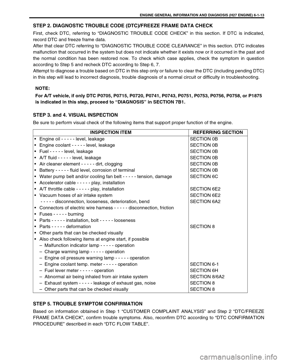
STEP 3. and 4. VISUAL INSPECTION
Be sure to perform visual check of the following items that support proper function of the engine.
STEP 5. TROUBLE SYMPTOM CONFIRMATION
Based on information obtained in Step 1 “CUSTOMER COMPLAINT ANALYSIS” and Step 2 “DTC/FREEZE
FRAME DATA CHECK”, confirm trouble symptoms. Also, reconfirm DTC according to “DTC CONFIRMATION
PROCEDURE” described in each “DTC FLOW TABLE”.NOTE:
For A/T vehicle, if only DTC P0705, P0715, P0720, P0741, P0743, P0751, P0753, P0756, P0758, or P1875
is indicated in this step, proceed to “DIAGNOSIS” in SECTION 7B1.
INSPECTION ITEM REFERRING SECTION
• Engine oil - - - - - level, leakage
• Engine coolant - - - - - level, leakage
• Fuel - - - - - level, leakage
• A/T fluid - - - - - level, leakage
• Air cleaner element - - - - - dirt, clogging
• Battery - - - - - fluid level, corrosion of terminal
• Water pump belt and/or cooling fan belt - - - - - tension, damage
• Accelerator cable - - - - - play, installation
• A/T throttle cable - - - - - play, installation
• Vacuum hoses of air intake system
- - - - - disconnection, looseness, deterioration, bend
• Connectors of electric wire harness - - - - - disconnection, friction
• Fuses - - - - - burning
• Parts - - - - - installation, bolt - - - - - looseness
• Parts - - - - - deformation
• Other parts that can be checked visually
• Also check following items at engine start, if possible
– Malfunction indicator lamp - - - - - operation
– Charge warning lamp - - - - - operation
– Engine oil pressure warning lamp - - - - - operation
– Engine coolant temp. meter - - - - - operation
– Fuel lever meter - - - - - operation
– Abnormal air being inhaled from air intake system
– Exhaust system - - - - - leakage of exhaust gas, noise
– Other parts that can be checked visuallySECTION 0B
SECTION 0B
SECTION 0B
SECTION 0B
SECTION 0B
SECTION 0B
SECTION 6C
SECTION 6E2
SECTION 6E2
SECTION 6A2
SECTION 8
SECTION 6-1
SECTION 6H
SECTION 8/6A2
SECTION 8
SECTION 8
Page 276 of 656

ENGINE GENERAL INFORMATION AND DIAGNOSIS (H27 ENGINE) 6-1-115
DTC P1510 Ecm Back-Up Power Supply Malfunction
WIRING DIAGRAM
CIRCUIT DESCRIPTION
Battery voltage is supplied to keep DTC memory, values that ECM has learned to control engine, etc. in ECM
even when ignition switch is turned OFF.
DTC DETECTING CONDITION AND TROUBLE AREA
DTC CONFIRMATION PROCEDURE
1) Connect scan tool to DLC with ignition switch OFF.
2) Turn ON ignition switch and clear DTC, pending DTC and freeze frame data by using scan tool and run
engine at idle speed for 1min.
3) Check DTC by using scan tool.
TROUBLESHOOTING
1. Main fuse box 3. ECM (PCM)
2. To DLC
DTC DETECTING CONDITION TROUBLE AREA
Back-up circuit voltage lower than specification is detected
while engine is running.•ECM (PCM) back-up circuit
•ECM (PCM)
NOTE:
Check to make sure that following condition is satisfied when using this “DTC CONFIRMATION PRO-
CEDURE”.
Intake air temp. : – 8°C (18°F) or higher
Engine coolant temp. : – 8 – 110°C (18 – 230°F)
Altitude (barometric pressure) : 2400 m, 8000 ft or less (560 mmHg (75 kPa) or more)
Step Action Yes No
1Was “ENGINE DIAG. FLOW TABLE” performed? Go to Step 2. Go to “ENGINE DIAG. FLOW
TABLE” in this section.
2 Battery voltage supply circuit check :
1) Remove ECM (PCM) cover.
2) While engine running, check voltage between E61-
2 and ground.
Is voltage 10 – 14 V?Poor E61-2 connection or
intermittent trouble.
Check for intermittent referring
to “INTERMITTENT AND
POOR CONNECTION” in
Section 0A.
If wire and connections are
OK, substitute a known-good
ECM (PCM) and recheck.“WHT” circuit open or short.
Page 296 of 656

ENGINE MECHANICAL (H27 ENGINE) 6A2-9
26) Upon completion of installation, verify that there is no fuel
leakage at each connection according to procedure
described in Section 6.
Exhaust Manifold
REMOVAL
1) Disconnect negative (–) cable at battery.
2) Remove air cleaner upper case and intake air hose if right
side exhaust manifold is removed.
3) Detach couplers from their bracket and disconnect oxygen
sensor lead wires at couplers. WARNING:
To avoid danger of being burned, do not service exhaust
system while it is still hot. Service should be performed
after system has cooled off.
1. Left (No.1) exhaust manifold
Right (No.2) exhaust manifold
2. Exhaust manifold cover
3. Exhaust No.1 pipe
A. Without WU-TWC
B. With WU-TWC
1. HO2S-1 (Green connector)
2. HO2S-2 (Black connector)
Page 307 of 656

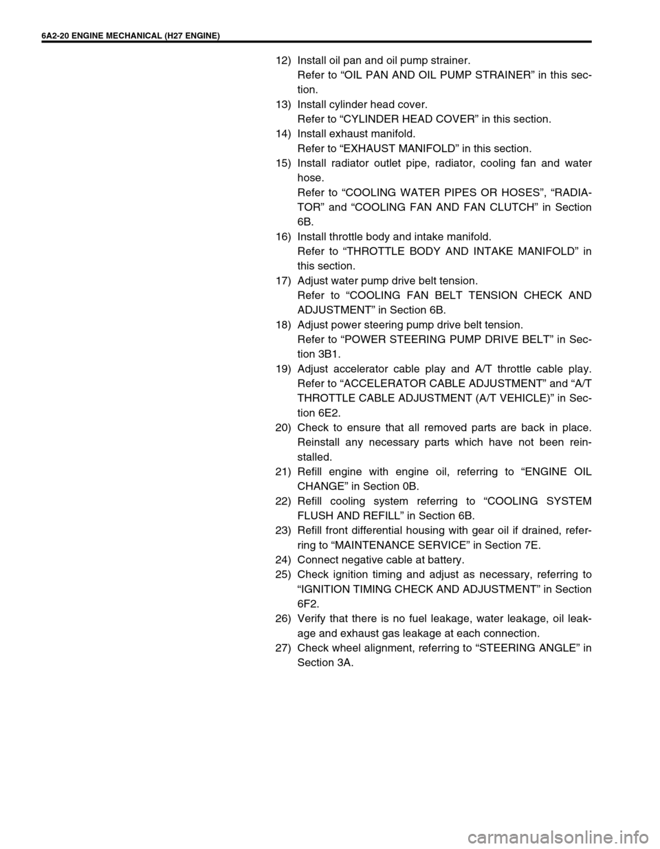
6A2-20 ENGINE MECHANICAL (H27 ENGINE)
12) Install oil pan and oil pump strainer.
Refer to “OIL PAN AND OIL PUMP STRAINER” in this sec-
tion.
13) Install cylinder head cover.
Refer to “CYLINDER HEAD COVER” in this section.
14) Install exhaust manifold.
Refer to “EXHAUST MANIFOLD” in this section.
15) Install radiator outlet pipe, radiator, cooling fan and water
hose.
Refer to “COOLING WATER PIPES OR HOSES”, “RADIA-
TOR” and “COOLING FAN AND FAN CLUTCH” in Section
6B.
16) Install throttle body and intake manifold.
Refer to “THROTTLE BODY AND INTAKE MANIFOLD” in
this section.
17) Adjust water pump drive belt tension.
Refer to “COOLING FAN BELT TENSION CHECK AND
ADJUSTMENT” in Section 6B.
18) Adjust power steering pump drive belt tension.
Refer to “POWER STEERING PUMP DRIVE BELT” in Sec-
tion 3B1.
19) Adjust accelerator cable play and A/T throttle cable play.
Refer to “ACCELERATOR CABLE ADJUSTMENT” and “A/T
THROTTLE CABLE ADJUSTMENT (A/T VEHICLE)” in Sec-
tion 6E2.
20) Check to ensure that all removed parts are back in place.
Reinstall any necessary parts which have not been rein-
stalled.
21) Refill engine with engine oil, referring to “ENGINE OIL
CHANGE” in Section 0B.
22) Refill cooling system referring to “COOLING SYSTEM
FLUSH AND REFILL” in Section 6B.
23) Refill front differential housing with gear oil if drained, refer-
ring to “MAINTENANCE SERVICE” in Section 7E.
24) Connect negative cable at battery.
25) Check ignition timing and adjust as necessary, referring to
“IGNITION TIMING CHECK AND ADJUSTMENT” in Section
6F2.
26) Verify that there is no fuel leakage, water leakage, oil leak-
age and exhaust gas leakage at each connection.
27) Check wheel alignment, referring to “STEERING ANGLE” in
Section 3A.
Page 365 of 656

6E2-32 ENGINE AND EMISSION CONTROL SYSTEM (SEQUENTIAL MULTIPORT FUEL INJECTION FOR H27 ENGINE)
Mass air flow sensor (MAF sensor)
INSPECTION
1) Connect voltmeter (1) to “B+” terminal of MAF sensor (2)
coupler disconnected and ground (3).
2) Turn ignition switch ON and check that voltage is battery volt-
age.If not, check if wire harness is open or connection is
poor.
3) Turn ignition switch OFF and remove ECM/PCM cover (1)
from bracket.
4) Connect MAF sensor coupler to MAF sensor.
5) Turn ignition switch ON and check voltage at MAF sensor
output terminal of ECM/PCM connector (1).
MAF sensor output voltage
Voltage: 1.0 - 1.6 V
6) Start engine and check that voltage is lower than 5 V and it
rises as engine speed increases.
(Reference data: 1.7 – 2.0 V at specified idle speed)
If check result is not as specified above, cause may lie in
wire harness, coupler connection, MAF sensor or ECM/
PCM. NOTE:
Use voltmeter with high-impedance (10 kΩ
ΩΩ Ω/V minimum)
or digital type voltmeter.