1999 SUZUKI GRAND VITARA Indicator fuse
[x] Cancel search: Indicator fusePage 174 of 656

ENGINE GENERAL INFORMATION AND DIAGNOSIS (H27 ENGINE) 6-1-13
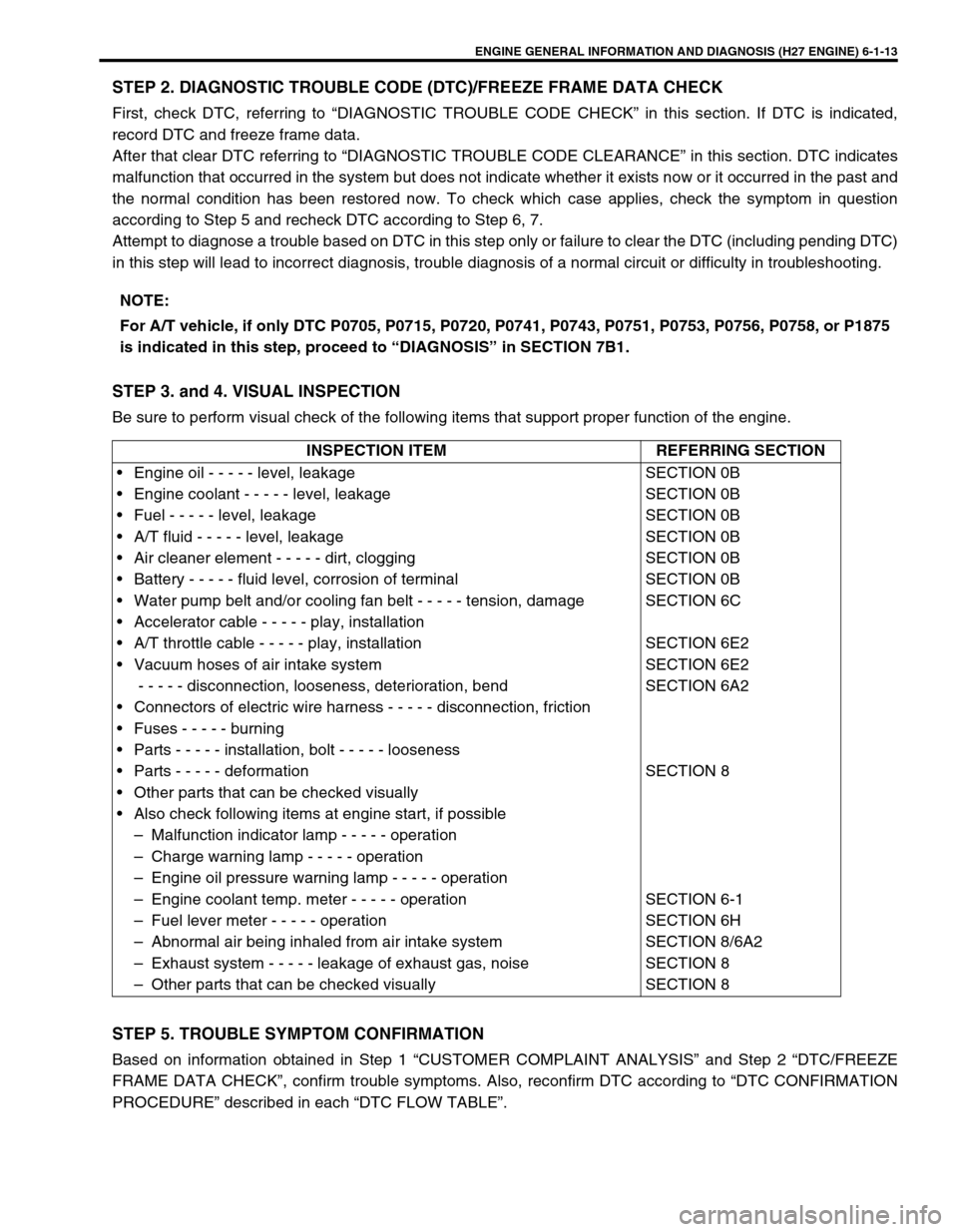
STEP 2. DIAGNOSTIC TROUBLE CODE (DTC)/FREEZE FRAME DATA CHECK
First, check DTC, referring to “DIAGNOSTIC TROUBLE CODE CHECK” in this section. If DTC is indicated,
record DTC and freeze frame data.
After that clear DTC referring to “DIAGNOSTIC TROUBLE CODE CLEARANCE” in this section. DTC indicates
malfunction that occurred in the system but does not indicate whether it exists now or it occurred in the past and
the normal condition has been restored now. To check which case applies, check the symptom in question
according to Step 5 and recheck DTC according to Step 6, 7.
Attempt to diagnose a trouble based on DTC in this step only or failure to clear the DTC (including pending DTC)
in this step will lead to incorrect diagnosis, trouble diagnosis of a normal circuit or difficulty in troubleshooting.
STEP 3. and 4. VISUAL INSPECTION
Be sure to perform visual check of the following items that support proper function of the engine.
STEP 5. TROUBLE SYMPTOM CONFIRMATION
Based on information obtained in Step 1 “CUSTOMER COMPLAINT ANALYSIS” and Step 2 “DTC/FREEZE
FRAME DATA CHECK”, confirm trouble symptoms. Also, reconfirm DTC according to “DTC CONFIRMATION
PROCEDURE” described in each “DTC FLOW TABLE”.NOTE:
For A/T vehicle, if only DTC P0705, P0715, P0720, P0741, P0743, P0751, P0753, P0756, P0758, or P1875
is indicated in this step, proceed to “DIAGNOSIS” in SECTION 7B1.
INSPECTION ITEM REFERRING SECTION
• Engine oil - - - - - level, leakage
• Engine coolant - - - - - level, leakage
• Fuel - - - - - level, leakage
• A/T fluid - - - - - level, leakage
• Air cleaner element - - - - - dirt, clogging
• Battery - - - - - fluid level, corrosion of terminal
• Water pump belt and/or cooling fan belt - - - - - tension, damage
• Accelerator cable - - - - - play, installation
• A/T throttle cable - - - - - play, installation
• Vacuum hoses of air intake system
- - - - - disconnection, looseness, deterioration, bend
• Connectors of electric wire harness - - - - - disconnection, friction
• Fuses - - - - - burning
• Parts - - - - - installation, bolt - - - - - looseness
• Parts - - - - - deformation
• Other parts that can be checked visually
• Also check following items at engine start, if possible
– Malfunction indicator lamp - - - - - operation
– Charge warning lamp - - - - - operation
– Engine oil pressure warning lamp - - - - - operation
– Engine coolant temp. meter - - - - - operation
– Fuel lever meter - - - - - operation
– Abnormal air being inhaled from air intake system
– Exhaust system - - - - - leakage of exhaust gas, noise
– Other parts that can be checked visuallySECTION 0B
SECTION 0B
SECTION 0B
SECTION 0B
SECTION 0B
SECTION 0B
SECTION 6C
SECTION 6E2
SECTION 6E2
SECTION 6A2
SECTION 8
SECTION 6-1
SECTION 6H
SECTION 8/6A2
SECTION 8
SECTION 8
Page 178 of 656
![SUZUKI GRAND VITARA 1999 2.G Owners Manual ENGINE GENERAL INFORMATION AND DIAGNOSIS (H27 ENGINE) 6-1-17
[Without Using SUZUKI Scan Tool] (Vehicle with Monitor
Connector)
1) Check malfunction indicator lamp referring to “Malfunction
Indicato SUZUKI GRAND VITARA 1999 2.G Owners Manual ENGINE GENERAL INFORMATION AND DIAGNOSIS (H27 ENGINE) 6-1-17
[Without Using SUZUKI Scan Tool] (Vehicle with Monitor
Connector)
1) Check malfunction indicator lamp referring to “Malfunction
Indicato](/manual-img/20/7583/w960_7583-177.png)
ENGINE GENERAL INFORMATION AND DIAGNOSIS (H27 ENGINE) 6-1-17
[Without Using SUZUKI Scan Tool] (Vehicle with Monitor
Connector)
1) Check malfunction indicator lamp referring to “Malfunction
Indicator Lamp Check” in this section.
2) With the ignition switch OFF position, disconnect SUZUKI
scan tool if connected and using service wire (4), connect
diagnosis switch terminal (1) to ground terminal (2) in moni-
tor connector (3).
3) With the ignition switch ON position and leaving engine OFF,
read DTC from flashing pattern of malfunction indicator
lamp. Refer to “Diagnostic Trouble Code Table”.
If lamp remains ON, go to “Diagnostic Flow Table A-4”.
4) After completing the check, turn the ignition switch OFF posi-
tion and disconnect service wire from monitor coupler.
Diagnostic Trouble Code (DTC) Clearance
[Using scan tool]
1) With ignition switch OFF, connect generic scan tool or
SUZUKI scan tool to data link connector (DLC).
2) Turn ignition switch ON.
3) Erase DTC according to instructions displayed on scan tool.
Freeze frame data is cleared with the DTC. Refer to scan tool
operator’s manual for further details.
4) After completing the clearance, turn ignition switch off and
disconnect scan tool from data link connector. NOTE:
If abnormality or malfunction lies in two or more areas,
malfunction indicator lamp indicates applicable codes
three times each.
And flashing of these codes is repeated as long as
diagnosis terminal is grounded and ignition switch is
held at ON position.
Take a note of diagnostic trouble code indicated first.
NOTE:
DTC and freeze frame data stored in ECM (PCM) memory
are also cleared in following cases. Be careful not to
clear them before keeping their record.
When power to ECM (PCM) is cut off (by disconnecting
battery cable, removing fuse or disconnecting ECM
(PCM) connectors)
When the same malfunction (DTC) is not detected
again during 40 engine warm-up cycles (refer to
“WARM-UP CYCLE” of “ON-BOARD DIAGNOSTIC SYS-
TEM” in this section) (Vehicle without monitor connec-
tor)
Page 204 of 656

ENGINE GENERAL INFORMATION AND DIAGNOSIS (H27 ENGINE) 6-1-43
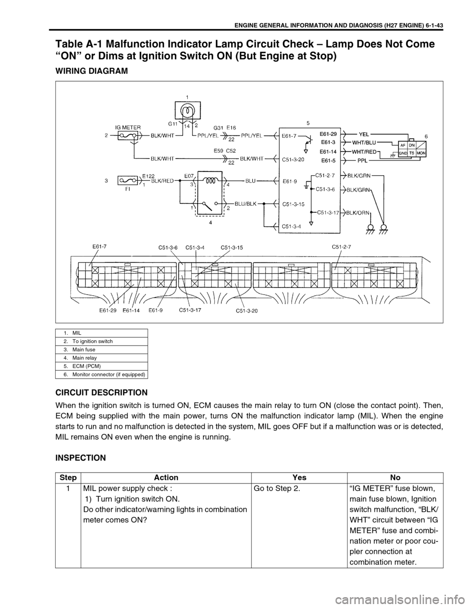
Table A-1 Malfunction Indicator Lamp Circuit Check – Lamp Does Not Come
“ON” or Dims at Ignition Switch ON (But Engine at Stop)
WIRING DIAGRAM
CIRCUIT DESCRIPTION
When the ignition switch is turned ON, ECM causes the main relay to turn ON (close the contact point). Then,
ECM being supplied with the main power, turns ON the malfunction indicator lamp (MIL). When the engine
starts to run and no malfunction is detected in the system, MIL goes OFF but if a malfunction was or is detected,
MIL remains ON even when the engine is running.
INSPECTION
1. MIL
2. To ignition switch
3. Main fuse
4. Main relay
5. ECM (PCM)
6. Monitor connector (if equipped)
Step Action Yes No
1 MIL power supply check :
1) Turn ignition switch ON.
Do other indicator/warning lights in combination
meter comes ON?Go to Step 2. “IG METER” fuse blown,
main fuse blown, Ignition
switch malfunction, “BLK/
WHT” circuit between “IG
METER” fuse and combi-
nation meter or poor cou-
pler connection at
combination meter.
Page 341 of 656

6E2-8 ENGINE AND EMISSION CONTROL SYSTEM (SEQUENTIAL MULTIPORT FUEL INJECTION FOR H27 ENGINE)
Electronic Control System
The electronic control system consists of 1) various sensors which detect the state of engine and driving condi-
tions, 2) ECM (PCM) which controls various devices according to the signals from the sensors and 3) various
controlled devices.
Functionally, it is divided into the following sub systems:
•Fuel injection control system
•Heated oxygen sensor heater control system (if equipped)
•Idle air control system
•Fuel pump control system
•Evaporative emission control system
•Ignition control system
•EGR system (if equipped)
Also, with A/T model, PCM controls A/T.
INFORMATION SENSORS CONTROLLED DEVICES OTHERS
1. IAT sensor a : A/C condenser fan motor relay (if equipped) A : Main fuse box
2. MAP sensor (if equipped) b : Ignition coil assemblies B : ECM (PCM)
3. Heated oxygen sensor (sensor 1) (if equipped) c : EVAP canister purge valve C : Data link connector
4. ECT sensor d : EGR valve (if equipped) D : Combination meter
5. TP sensor e : Idle air control valve E : Fuse box
6. MAF sensor f : Injectors F : EVAP canister
7. Camshaft position sensor (CMP sensor) g : Malfunction indicator lamp
8. ABS control module h : Fuel pump relay
9. Crankshaft position sensor (CKP sensor) (if equipped) i : Main relay
10. Power steering pressure switch (PSP switch) j : Oxygen sensor heater relay (if equipped)
11. CO adjusting resistor (if equipped)
12. Monitor connector (if equipped)
13. Transmission range switch (A/T)
14. Knock sensor
NOTE:
Above figure shows left-hand steering vehicle. For right-hand steering vehicle, parts with (*) are
installed at the side of symmetry.
Page 423 of 656

7B1-14 AUTOMATIC TRANSMISSION (4 A/T)
Diagnostic Trouble Code Table
Refer to the same item in Section 6-1.
Fail Safe Table
Refer to the same item in Section 6-1.
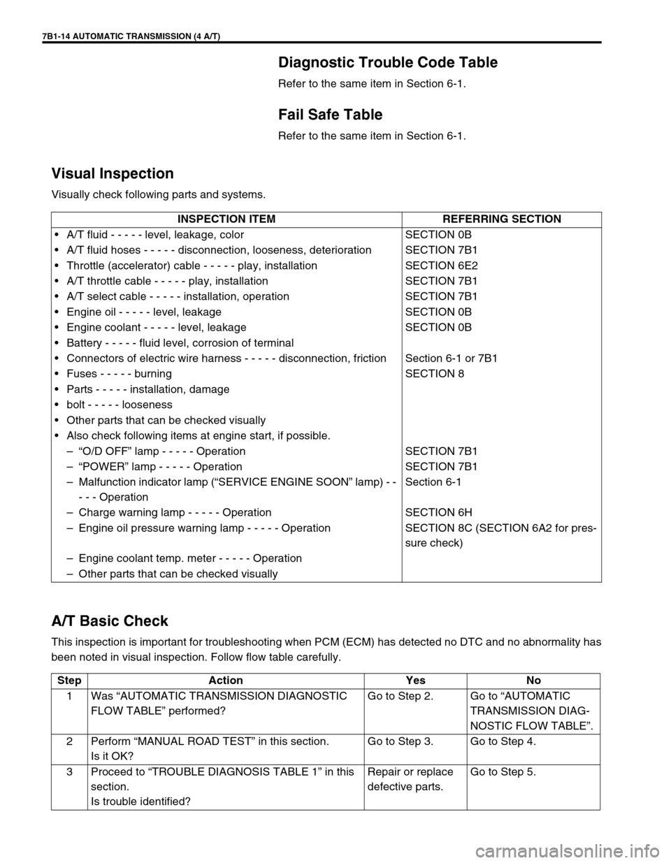
Visual Inspection
Visually check following parts and systems.
A/T Basic Check
This inspection is important for troubleshooting when PCM (ECM) has detected no DTC and no abnormality has
been noted in visual inspection. Follow flow table carefully.INSPECTION ITEM REFERRING SECTION
•A/T fluid - - - - - level, leakage, color SECTION 0B
•A/T fluid hoses - - - - - disconnection, looseness, deterioration SECTION 7B1
•Throttle (accelerator) cable - - - - - play, installation SECTION 6E2
•A/T throttle cable - - - - - play, installation SECTION 7B1
•A/T select cable - - - - - installation, operation SECTION 7B1
•Engine oil - - - - - level, leakage SECTION 0B
•Engine coolant - - - - - level, leakage SECTION 0B
•Battery - - - - - fluid level, corrosion of terminal
•Connectors of electric wire harness - - - - - disconnection, friction Section 6-1 or 7B1
•Fuses - - - - - burning SECTION 8
•Parts - - - - - installation, damage
•bolt - - - - - looseness
•Other parts that can be checked visually
•Also check following items at engine start, if possible.
–“O/D OFF” lamp - - - - - Operation SECTION 7B1
–“POWER” lamp - - - - - Operation SECTION 7B1
–Malfunction indicator lamp (“SERVICE ENGINE SOON” lamp) - -
- - - OperationSection 6-1
–Charge warning lamp - - - - - Operation SECTION 6H
–Engine oil pressure warning lamp - - - - - Operation SECTION 8C (SECTION 6A2 for pres-
sure check)
–Engine coolant temp. meter - - - - - Operation
–Other parts that can be checked visually
Step Action Yes No
1Was “AUTOMATIC TRANSMISSION DIAGNOSTIC
FLOW TABLE” performed?Go to Step 2. Go to “AUTOMATIC
TRANSMISSION DIAG-
NOSTIC FLOW TABLE”.
2Perform “MANUAL ROAD TEST” in this section.
Is it OK?Go to Step 3. Go to Step 4.
3Proceed to “TROUBLE DIAGNOSIS TABLE 1” in this
section.
Is trouble identified?Repair or replace
defective parts.Go to Step 5.
Page 522 of 656

CRUISE CONTROL SYSTEM 8E-1
6F1
6F2
6G
6H
6K
7A
7A1
7B1
7C1
7D
7E
8E
8A
8B
8C
8D
8B
9
10
10A
10B
SECTION 8E
CRUISE CONTROL SYSTEM
CONTENTS
General Description ....................................... 8E-2
Cautions in Servicing ................................... 8E-2
Symbols and Marks ...................................... 8E-2
Abbreviations ............................................... 8E-2
Wiring Color Symbols ................................... 8E-2
Joint Connector ............................................ 8E-2
Fuse Box and Relay ..................................... 8E-2
Power Supply Diagram ................................ 8E-2
Cruise Control System ................................. 8E-3
Cruise control system circuit .................... 8E-3
Components and functions....................... 8E-4
Cancel Conditions .................................... 8E-5
Diagnosis ........................................................ 8E-5
Diagnosis Table ........................................... 8E-5
Note on System Circuit Inspection ............... 8E-7
Cruise Main Switch Indicator Lamp
Circuit Check ................................................ 8E-8
“Cruise” Indicator Lamp Circuit Check ......... 8E-9
Cruise Main Switch, Coast/Set,
Resume/Accel and Cancel Switches
Circuits Check ............................................ 8E-10
VSS Circuit Check ...................................... 8E-11
Stop Lamp Switch (with Pedal Position
Switch) Circuits Check ............................... 8E-12Transmission Range Switch Circuit Check 8E-13
Clutch Pedal Position Switch Circuit Check 8E-14
Throttle Valve Opening Signal Circuit
Check ......................................................... 8E-15
Overdrive and TCC off Command Signal
Circuit Check.............................................. 8E-16
Cruise Control Module Power and Ground
Circuits Check ............................................ 8E-16
Cruise Control Module and Its Circuit
Inspection................................................... 8E-17
Cruise Cable Play Inspection and
Adjustment ................................................. 8E-19
On-Vehicle Service ...................................... 8E-19
Cruise Main Switch .................................... 8E-19
Coast/Set, Resume/Accel and Cancel
Switches..................................................... 8E-20
Vehicle Speed Sensor (VSS) ..................... 8E-20
Transmission Range Switch ...................... 8E-20
Clutch Pedal Position (CPP) Switch .......... 8E-21
Stop Lamp Switch (with Pedal Position
Switch) ....................................................... 8E-22
Cruise Control Actuator Assembly
(with Control Module) ................................. 8E-23
Cruise Cable .............................................. 8E-24
WARNING:
For vehicles equipped with Supplemental Restraint (Air Bag) System:
Service on and around the air bag system components or wiring must be performed only by an
authorized SUZUKI dealer. Refer to “Air Bag System Components and Wiring Location View” under
“General Description” in air bag system section in order to confirm whether you are performing ser-
vice on or near the air bag system components or wiring. Please observe all WARNINGS and “Ser-
vice Precautions” under “On-Vehicle Service” in air bag system section before performing service
on or around the air bag system components or wiring. Failure to follow WARNINGS could result in
unintentional activation of the system or could render the system inoperative. Either of these two
conditions may result in severe injury.
Technical service work must be started at least 90 seconds after the ignition switch is turned to the
“LOCK” position and the negative cable is disconnected from the battery. Otherwise, the system
may be activated by reserve energy in the Sensing and Diagnostic Module (SDM).
Page 595 of 656

10B-18 AIR BAG SYSTEM
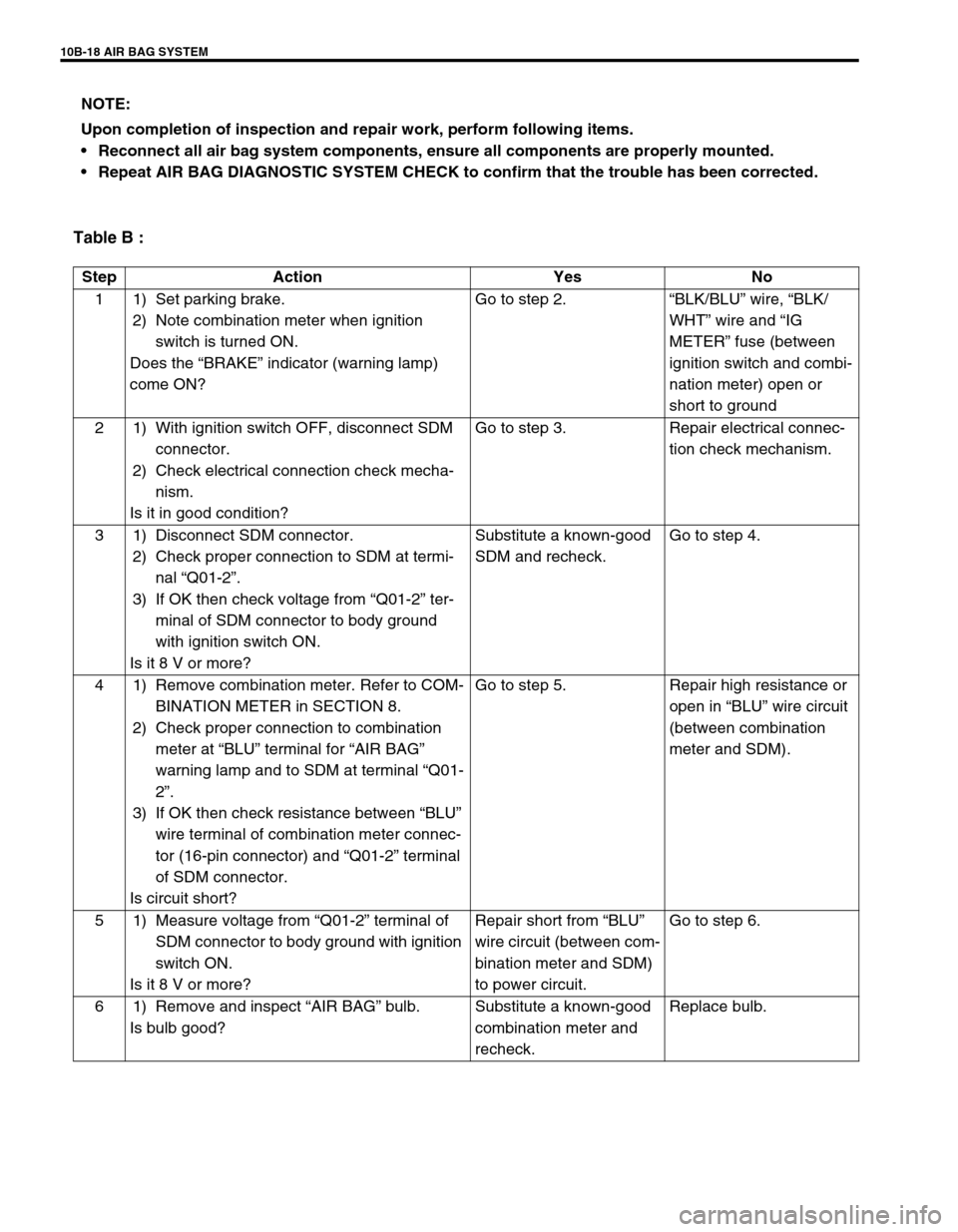
Table B :
NOTE:
Upon completion of inspection and repair work, perform following items.
Reconnect all air bag system components, ensure all components are properly mounted.
Repeat AIR BAG DIAGNOSTIC SYSTEM CHECK to confirm that the trouble has been corrected.
Step Action Yes No
1 1) Set parking brake.
2) Note combination meter when ignition
switch is turned ON.
Does the “BRAKE” indicator (warning lamp)
come ON?Go to step 2.“BLK/BLU” wire, “BLK/
WHT” wire and “IG
METER” fuse (between
ignition switch and combi-
nation meter) open or
short to ground
2 1) With ignition switch OFF, disconnect SDM
connector.
2) Check electrical connection check mecha-
nism.
Is it in good condition?Go to step 3. Repair electrical connec-
tion check mechanism.
3 1) Disconnect SDM connector.
2) Check proper connection to SDM at termi-
nal “Q01-2”.
3) If OK then check voltage from “Q01-2” ter-
minal of SDM connector to body ground
with ignition switch ON.
Is it 8 V or more?Substitute a known-good
SDM and recheck.Go to step 4.
4 1) Remove combination meter. Refer to COM-
BINATION METER in SECTION 8.
2) Check proper connection to combination
meter at “BLU” terminal for “AIR BAG”
warning lamp and to SDM at terminal “Q01-
2”.
3) If OK then check resistance between “BLU”
wire terminal of combination meter connec-
tor (16-pin connector) and “Q01-2” terminal
of SDM connector.
Is circuit short?Go to step 5. Repair high resistance or
open in “BLU” wire circuit
(between combination
meter and SDM).
5 1) Measure voltage from “Q01-2” terminal of
SDM connector to body ground with ignition
switch ON.
Is it 8 V or more?Repair short from “BLU”
wire circuit (between com-
bination meter and SDM)
to power circuit.Go to step 6.
6 1) Remove and inspect “AIR BAG” bulb.
Is bulb good?Substitute a known-good
combination meter and
recheck.Replace bulb.