1999 SUZUKI GRAND VITARA troubleshooting
[x] Cancel search: troubleshootingPage 7 of 656

0A-2 GENERAL INFORMATION
Precautions
Precaution for Vehicles Equipped with A Sup-
plemental Restraint
(Air Bag) System
Diagnosis
When troubleshooting air bag system, be sure to follow
“DIAGNOSIS” in SECTION 10B. Bypassing these proce-
dures may result in extended diagnostic time, incorrect
diagnosis, and incorrect parts replacement.
Never use electrical test equipment other than that
specified in this manual. WARNING:
The configuration of air bag system parts are as shown
in the figure. When it is necessary to service (remove,
reinstall and inspect) these parts, be sure to follow
procedures described in SECTION 10B. Failure to fol-
low proper procedures could result in possible air bag
system activation, personal injury, damage to parts or
air bag system being unable to activate when neces-
sary.
If the air bag system and another vehicle system both
need repair, SUZUKI recommends that the air bag sys-
tem be repaired first, to help avoid unintended air bag
system activation.
Do not modify the steering wheel, dashboard, or any
other air bag system components. Modifications can
adversely affect air bag system performance and lead
to injury.
If the vehicle will be exposed to temperatures over
93°C (200°F) (for example, during a paint baking pro-
cess), remove the air bag system components before-
hand to avoid component damage or unintended air
bag system activation.
1. Air bag wire harness 5. Contact coil
2. Passenger air bag (inflator) module 6. Driver air bag (inflator) module
3. SDM 7. Forward sensors
4. Seat belt pretensioners
15
2 6
7
5
3
44 7
1
WARNING:
Never attempt to measure the resistance of the air bag
(inflator) modules (driver and passenger) and seat belt
pretensioners (driver and passenger). It is very danger-
ous as the electric current from the tester may deploy the
air bag or activate the pretensioners.
Page 174 of 656

ENGINE GENERAL INFORMATION AND DIAGNOSIS (H27 ENGINE) 6-1-13
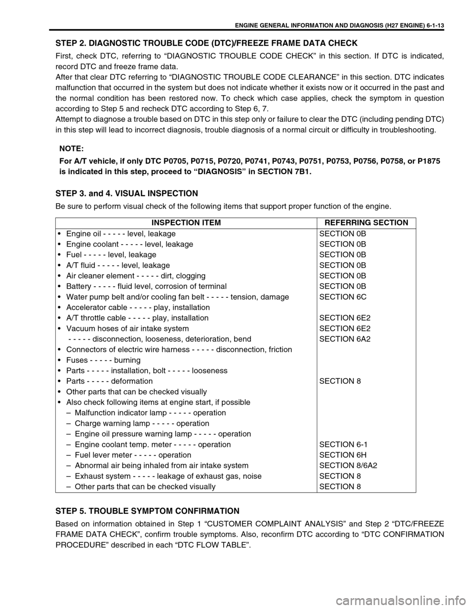
STEP 2. DIAGNOSTIC TROUBLE CODE (DTC)/FREEZE FRAME DATA CHECK
First, check DTC, referring to “DIAGNOSTIC TROUBLE CODE CHECK” in this section. If DTC is indicated,
record DTC and freeze frame data.
After that clear DTC referring to “DIAGNOSTIC TROUBLE CODE CLEARANCE” in this section. DTC indicates
malfunction that occurred in the system but does not indicate whether it exists now or it occurred in the past and
the normal condition has been restored now. To check which case applies, check the symptom in question
according to Step 5 and recheck DTC according to Step 6, 7.
Attempt to diagnose a trouble based on DTC in this step only or failure to clear the DTC (including pending DTC)
in this step will lead to incorrect diagnosis, trouble diagnosis of a normal circuit or difficulty in troubleshooting.
STEP 3. and 4. VISUAL INSPECTION
Be sure to perform visual check of the following items that support proper function of the engine.
STEP 5. TROUBLE SYMPTOM CONFIRMATION
Based on information obtained in Step 1 “CUSTOMER COMPLAINT ANALYSIS” and Step 2 “DTC/FREEZE
FRAME DATA CHECK”, confirm trouble symptoms. Also, reconfirm DTC according to “DTC CONFIRMATION
PROCEDURE” described in each “DTC FLOW TABLE”.NOTE:
For A/T vehicle, if only DTC P0705, P0715, P0720, P0741, P0743, P0751, P0753, P0756, P0758, or P1875
is indicated in this step, proceed to “DIAGNOSIS” in SECTION 7B1.
INSPECTION ITEM REFERRING SECTION
• Engine oil - - - - - level, leakage
• Engine coolant - - - - - level, leakage
• Fuel - - - - - level, leakage
• A/T fluid - - - - - level, leakage
• Air cleaner element - - - - - dirt, clogging
• Battery - - - - - fluid level, corrosion of terminal
• Water pump belt and/or cooling fan belt - - - - - tension, damage
• Accelerator cable - - - - - play, installation
• A/T throttle cable - - - - - play, installation
• Vacuum hoses of air intake system
- - - - - disconnection, looseness, deterioration, bend
• Connectors of electric wire harness - - - - - disconnection, friction
• Fuses - - - - - burning
• Parts - - - - - installation, bolt - - - - - looseness
• Parts - - - - - deformation
• Other parts that can be checked visually
• Also check following items at engine start, if possible
– Malfunction indicator lamp - - - - - operation
– Charge warning lamp - - - - - operation
– Engine oil pressure warning lamp - - - - - operation
– Engine coolant temp. meter - - - - - operation
– Fuel lever meter - - - - - operation
– Abnormal air being inhaled from air intake system
– Exhaust system - - - - - leakage of exhaust gas, noise
– Other parts that can be checked visuallySECTION 0B
SECTION 0B
SECTION 0B
SECTION 0B
SECTION 0B
SECTION 0B
SECTION 6C
SECTION 6E2
SECTION 6E2
SECTION 6A2
SECTION 8
SECTION 6-1
SECTION 6H
SECTION 8/6A2
SECTION 8
SECTION 8
Page 176 of 656

ENGINE GENERAL INFORMATION AND DIAGNOSIS (H27 ENGINE) 6-1-15
STEP 9. TROUBLESHOOTING FOR DTC
Based on the DTC indicated in Step 6 or 7 and referring to the applicable DTC diag. flow table in this section,
locate the cause of the trouble, namely in a sensor, switch, wire harness, connector, actuator, ECM (PCM) or
other part and repair or replace faulty parts.
STEP 10. CHECK FOR INTERMITTENT PROBLEM
Check parts where an intermittent trouble is easy to occur (e.g., wire harness, connector, etc.), referring to
“INTERMITTENT AND POOR CONNECTION” in Section 0A and related circuit of DTC recorded in step 2.
STEP 11. FINAL CONFIRMATION TEST
Confirm that the problem symptom has gone and the engine is free from any abnormal conditions. If what has
been repaired is related to the DTC, clear the DTC once, perform DTC confirmation procedure and confirm that
no malfunction DTC (a normal code) is indicated.
Page 177 of 656

6-1-16 ENGINE GENERAL INFORMATION AND DIAGNOSIS (H27 ENGINE)
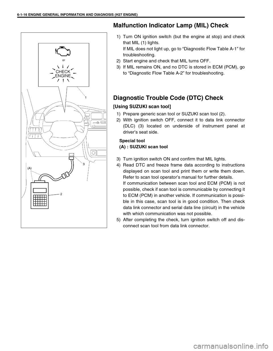
Malfunction Indicator Lamp (MIL) Check
1) Turn ON ignition switch (but the engine at stop) and check
that MIL (1) lights.
If MIL does not light up, go to “Diagnostic Flow Table A-1” for
troubleshooting.
2) Start engine and check that MIL turns OFF.
3) If MIL remains ON, and no DTC is stored in ECM (PCM), go
to “Diagnostic Flow Table A-2” for troubleshooting.
Diagnostic Trouble Code (DTC) Check
[Using SUZUKI scan tool]
1) Prepare generic scan tool or SUZUKI scan tool (2).
2) With ignition switch OFF, connect it to data link connector
(DLC) (3) located on underside of instrument panel at
driver’s seat side.
Special tool
(A) : SUZUKI scan tool
3) Turn ignition switch ON and confirm that MIL lights.
4) Read DTC and freeze frame data according to instructions
displayed on scan tool and print them or write them down.
Refer to scan tool operator’s manual for further details.
If communication between scan tool and ECM (PCM) is not
possible, check if scan tool is communicable by connecting it
to ECM (PCM) in another vehicle. If communication is possi-
ble in this case, scan tool is in good condition. Then check
data link connector and serial data line (circuit) in the vehicle
with which communication was not possible.
5) After completing the check, turn ignition switch off and dis-
connect scan tool from data link connector.
Page 192 of 656

ENGINE GENERAL INFORMATION AND DIAGNOSIS (H27 ENGINE) 6-1-31
Engine Diagnosis Table
Perform troubleshooting referring to following table when ECM (PCM) has detected no DTC and no abnormality
has been found in visual inspection and engine basic inspection previously.
Condition Possible Cause Correction
Hard starting
(Engine cranks OK)Faulty idle air control system “DIAG. FLOW TABLE B-4” in this
section.
Faulty ECT sensor or MAF sensor ECT sensor or MAF sensor in Sec-
tion 6E2.
Faulty ECM (PCM) Inspection of ECM (PCM) and its
circuit in this section.
Low compression Compression check in Section
6A2.
Faulty hydraulic valve lash adjuster Valve lash adjuster in Section 6A2.
Compression leak from valve seat Valves inspection in Section 6A2.
Sticky valve stem Valves inspection in Section 6A2.
Weak or damaged valve springs Valves spring inspection in Section
6A2.
Compression leak at cylinder head gasket Cylinder head inspection in Section
6A2.
Sticking or damaged piston ring Piston ring inspection in Section
6A2.
Worn piston, ring or cylinder Cylinders, pistons and piston rings
inspection in Section 6A2.
Malfunctioning PCV valve PCV system inspection in Section
6E2.
Engine has no power
Engine overheating Refer to “OVERHEATING” in this
table.
Defective spark plug Spark plugs in Section 6F2.
Faulty ignition coil with ignitor Ignition coil in Section 6F2.
Fuel pressure out of specification
(dirty fuel filter, dirty or clogged fuel hose or
pipe, malfunctioning fuel pressure regulator,
malfunctioning fuel pump)“DIAG. FLOW TABLE B-3” in this
section.
Maladjusted TP sensor installation angle TP sensor in Section 6E2.
Faulty EGR system “DTC P0400 DIAG. FLOW TABLE”
in this section.
Faulty injector Fuel injector in Section 6E2.
Faulty TP sensor, ECT sensor or MAF sensor TP sensor, ECT sensor or MAF
sensor in Section 6E2.
Faulty ECM (PCM) Inspection of ECM (PCM) and its
circuit in this section.
Low compression Refer to the same item in “HARD
STARTING” of this table.
Dragging brakes Diagnosis in Section 5.
Slipping clutch Diagnosis in Section 7C1.
Page 206 of 656

ENGINE GENERAL INFORMATION AND DIAGNOSIS (H27 ENGINE) 6-1-45
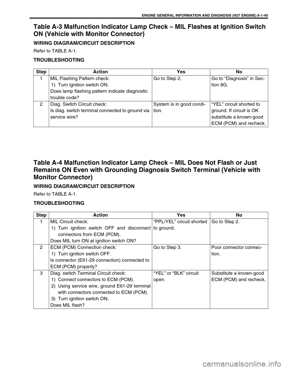
Table A-3 Malfunction Indicator Lamp Check – MIL Flashes at Ignition Switch
ON (Vehicle with Monitor Connector)
WIRING DIAGRAM/CIRCUIT DESCRIPTION
Refer to TABLE A-1.
TROUBLESHOOTING
Table A-4 Malfunction Indicator Lamp Check – MIL Does Not Flash or Just
Remains ON Even with Grounding Diagnosis Switch Terminal (Vehicle with
Monitor Connector)
WIRING DIAGRAM/CIRCUIT DESCRIPTION
Refer to TABLE A-1.
TROUBLESHOOTING
Step Action Yes No
1 MIL Flashing Pattern check:
1) Turn ignition switch ON.
Does lamp flashing pattern indicate diagnostic
trouble code?Go to Step 2. Go to “Diagnosis” in Sec-
tion 8G.
2 Diag. Switch Circuit check:
Is diag. switch terminal connected to ground via
service wire?System is in good condi-
tion.“YEL” circuit shorted to
ground. If circuit is OK
substitute a known-good
ECM (PCM) and recheck.
Step Action Yes No
1 MIL Circuit check:
1) Turn ignition switch OFF and disconnect
connectors from ECM (PCM).
Does MIL turn ON at ignition switch ON?“PPL/YEL” circuit shorted
to ground.Go to Step 2.
2 ECM (PCM) Connection check:
1) Turn ignition switch OFF.
Is connector (E61-29 connection) connected to
ECM (PCM) properly?Go to Step 3. Poor connector connec-
tion.
3 Diag. switch Terminal Circuit check:
1) Connect connectors to ECM (PCM).
2) Using service wire, ground E61-29 terminal
with connectors connected to ECM (PCM).
3) Turn ignition switch ON.
Does MIL flash?“YEL” or “BLK” circuit
open.Substitute a known-good
ECM (PCM) and recheck.
Page 210 of 656

ENGINE GENERAL INFORMATION AND DIAGNOSIS (H27 ENGINE) 6-1-49
DTC CONFIRMATION PROCEDURE
1) Connect scan tool to DLC with ignition switch OFF.
2) Turn ON ignition switch and clear DTC, pending DTC and freeze frame data by using scan tool and run
engine at idle speed for 20 sec. or more.
3) Check DTC by using scan tool.
TROUBLESHOOTING
WARNING:
When performing a road test, select a place where there is no traffic or possibility of a traffic acci-
dent and be very careful during testing to avoid occurrence of an accident.
Road test should be carried out with 2 person, a driver and a tester, on a level road.
NOTE:
Check to make sure that following conditions are satisfied when using this “DTC CONFIRMATION
PROCEDURE”.
Intake air temp. : – 8°C (18°F) or higher
Engine coolant temp. : – 8 – 110°C (18 – 230°F)
Altitude (barometric pressure) : 2400 m, 8000 ft or less (560 mmHg, 75 kPa or more)
Step Action Yes No
1 Was “ENGINE DIAG. FLOW TABLE” per-
formed?Go to Step 2. Go to “ENGINE DIAG.
FLOW TABLE” in this
section.
2 MAF sensor check :
1) Connect scan tool to DLC with ignition
switch OFF.
2) Start engine and check MAF value dis-
played on scan tool. (Refer to “SCAN TOOL
DATA” in this section for normal value.)
Is normal value indicated?Intermittent trouble.
Check for intermittent
referring to “INTERMIT-
TENT AND POOR CON-
NECTION” in Section 0A.Go to Step 3.
3 MAF sensor power supply check :
1) With ignition switch OFF, disconnect MAF
sensor coupler.
2) With ignition switch ON, check voltage
between E154-3 of MAF sensor coupler and
ground.
Is voltage 10 – 14 V?Go to Step 4. Faulty “BLU/BLK” wire.
4 MAF sensor output voltage check :
1) With ignition switch OFF, connect MAF sen-
sor coupler.
2) Remove ECM (PCM) cover.
3) With ignition switch ON leaving engine OFF,
check voltage between C51-3-10 and C51-
3-5 terminal.
Is voltage 1.0 – 1.6 V?Poor C51-3-10 or/C51-3-5
terminal connection.
If OK, substitute a known-
good ECM (PCM) and
recheck.Faulty “PPL/WHT” wire.
Poor E154 coupler termi-
nal connection.
If wire and connection are
OK, substitute a known-
good MAF sensor and
recheck.
Page 212 of 656

ENGINE GENERAL INFORMATION AND DIAGNOSIS (H27 ENGINE) 6-1-51
TROUBLESHOOTING
Step Action Yes No
1 Was “ENGINE DIAG. FLOW TABLE” per-
formed?Go to Step 2. Go to “ENGINE DIAG.
FLOW TABLE” in this
section.
2 Check IAT sensor and its circuit :
1) Connect scan tool with ignition switch OFF.
2) Turn ignition switch ON.
3) Check intake air temp. displayed on scan
tool.
Is – 40°C (– 40°F) or 165°C (329°F) indicated?Go to Step 3. Intermittent trouble.
Check for intermittent
referring to “INTERMIT-
TENT AND POOR CON-
NECTION” in Section 0A.
3 Check wire harness :
1) Disconnect IAT sensor connector with igni-
tion switch OFF.
2) Check for proper connection to IAT sensor
at “LT BLU” and “GRY/YEL” wire terminals.
If OK, then with ignition switch ON, is voltage
applied to “LT BLU” wire terminal about 4 – 6 V?Go to Step 4. “LT BLU” wire open or
short, or poor C51-3-1
connection.
If wire and connection are
OK, substitute a known-
good ECM (PCM) and
recheck.
4 Check wire harness :
1) Using service wire, connect IAT sensor con-
nector terminals.
2) Turn ignition switch ON and check intake air
temp. displayed on scan tool.
Is 165°C (329°F) indicated?Replace IAT sensor. “GRY/YEL” wire open or
poor C51-3-25 connec-
tion.
If wire and connection are
OK, substitute a known-
good ECM (PCM) and
recheck.