Page 504 of 656

DIFFERENTIAL (REAR) 7F-19
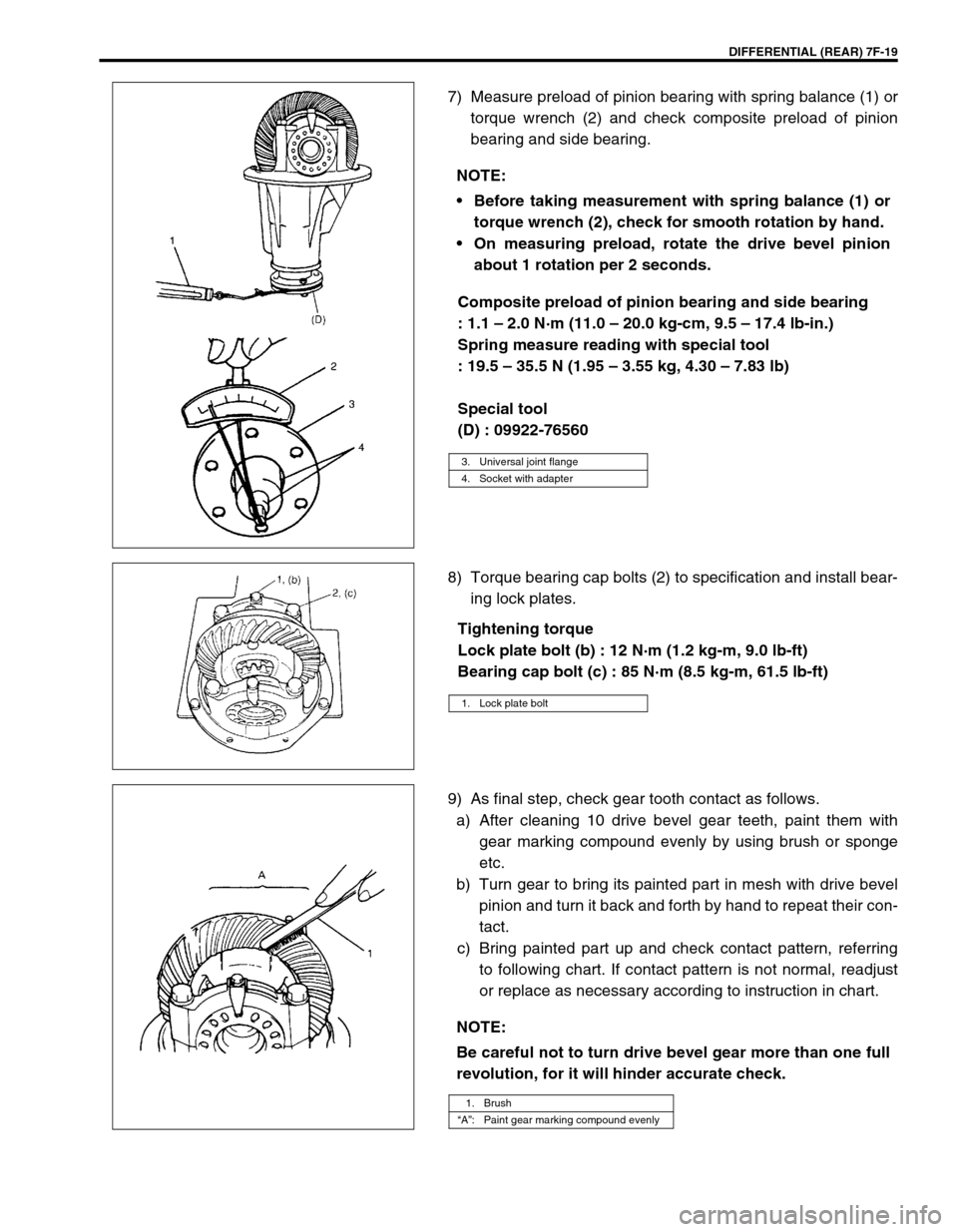
7) Measure preload of pinion bearing with spring balance (1) or
torque wrench (2) and check composite preload of pinion
bearing and side bearing.
Composite preload of pinion bearing and side bearing
: 1.1 – 2.0 N·m (11.0 – 20.0 kg-cm, 9.5 – 17.4 lb-in.)
Spring measure reading with special tool
: 19.5 – 35.5 N (1.95 – 3.55 kg, 4.30 – 7.83 lb)
Special tool
(D) : 09922-76560
8) Torque bearing cap bolts (2) to specification and install bear-
ing lock plates.
Tightening torque
Lock plate bolt (b) : 12 N·m (1.2 kg-m, 9.0 lb-ft)
Bearing cap bolt (c) : 85 N·m (8.5 kg-m, 61.5 lb-ft)
9) As final step, check gear tooth contact as follows.
a) After cleaning 10 drive bevel gear teeth, paint them with
gear marking compound evenly by using brush or sponge
etc.
b) Turn gear to bring its painted part in mesh with drive bevel
pinion and turn it back and forth by hand to repeat their con-
tact.
c) Bring painted part up and check contact pattern, referring
to following chart. If contact pattern is not normal, readjust
or replace as necessary according to instruction in chart. NOTE:
Before taking measurement with spring balance (1) or
torque wrench (2), check for smooth rotation by hand.
On measuring preload, rotate the drive bevel pinion
about 1 rotation per 2 seconds.
3. Universal joint flange
4. Socket with adapter
1. Lock plate bolt
NOTE:
Be careful not to turn drive bevel gear more than one full
revolution, for it will hinder accurate check.
1. Brush
“A”: Paint gear marking compound evenly
Page 506 of 656
DIFFERENTIAL (REAR) 7F-21
10) Upon completion of gear tooth contact check in Step 9),
caulk flange nut (2) with caulking tool (1) and hammer.
Tightening Torque Specification
Required Service Material
Fastening partTightening torque
Nm kg-m lb-ft
Differential oil level/filler plug 50 5.0 36.5
Differential oil drain plug 28 2.8 20.5
Propeller shaft flange nuts 60 6.0 43.5
Differential carrier bolts 55 5.5 40.0
Bevel gear bolts 105 10.5 76.0
Bearing cap bolts 85 8.5 61.5
Lock plate bolts 12 1.2 9.0
Differential case screws 9 0.9 6.5
MaterialRecommended SUZUKI product
(Part Number)Use
Thread lock cement THREAD LOCK CEMENT
SUPER 1322
(99000-32110)Bevel gear bolts
Differential case bolts
Bevel gear mating surface
Propeller shaft flange bolt
Lithium grease SUZUKI SUPER GREASE A
(99000-25010)Oil seal lips
Sealant SUZUKI BOND NO. 1215
(99000-31110)Rear differential drain plug
Mating surface of differential housing
Mating surface of rear axle housing
Page 508 of 656
DIFFERENTIAL (REAR) 7F-23
09928-06510 09930-40113 09930-40120 09944-66020
Differential torque
checking toolRotor holder Attachment Bearing installer
09951-16060 09951-18210 09951-46010
Lower arm bush remover Oil seal remover &
installer No. 2Drive shaft oil seal
installer
NOTE:
This tool is constituent of tools with 09926-78311.
Page 542 of 656

CRUISE CONTROL SYSTEM 8E-21
Clutch Pedal Position (CPP) Switch
REMOVAL
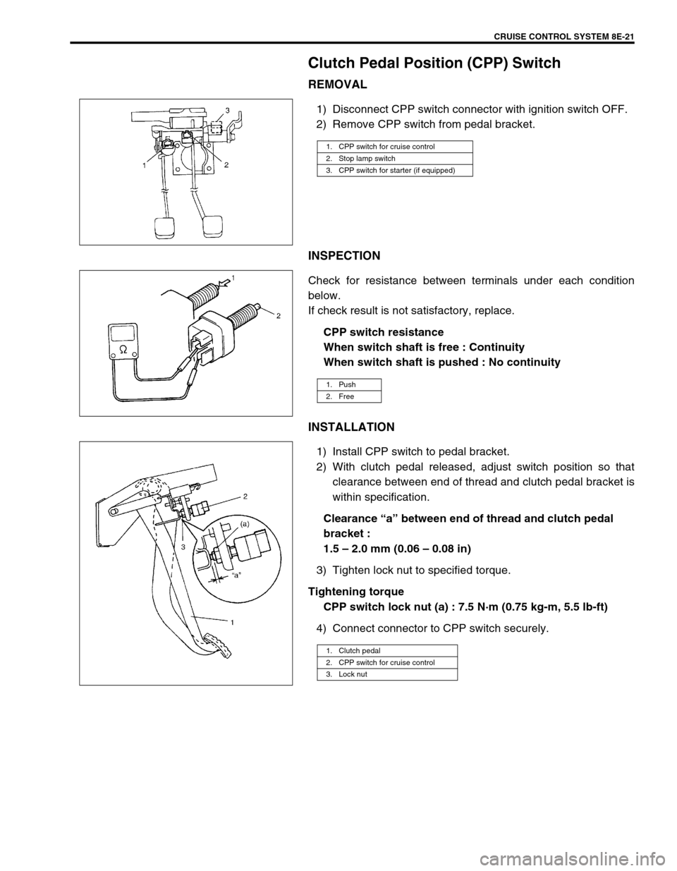
1) Disconnect CPP switch connector with ignition switch OFF.
2) Remove CPP switch from pedal bracket.
INSPECTION
Check for resistance between terminals under each condition
below.
If check result is not satisfactory, replace.
CPP switch resistance
When switch shaft is free : Continuity
When switch shaft is pushed : No continuity
INSTALLATION
1) Install CPP switch to pedal bracket.
2) With clutch pedal released, adjust switch position so that
clearance between end of thread and clutch pedal bracket is
within specification.
Clearance “a” between end of thread and clutch pedal
bracket :
1.5 – 2.0 mm (0.06 – 0.08 in)
3) Tighten lock nut to specified torque.
Tightening torque
CPP switch lock nut (a) : 7.5 N·m (0.75 kg-m, 5.5 lb-ft)
4) Connect connector to CPP switch securely.
1. CPP switch for cruise control
2. Stop lamp switch
3. CPP switch for starter (if equipped)
1. Push
2. Free
1. Clutch pedal
2. CPP switch for cruise control
3. Lock nut
Page 546 of 656

BODY SERVICE 9-1
9
SECTION 9
BODY SERVICE
CONTENTS
Glass, Windows and Mirror .............................. 9-2
Quarter Window .............................................. 9-2
Body Structure .................................................. 9-3
Under Body Dimensions ................................. 9-3
Body Dimensions ............................................ 9-4
Seat..................................................................... 9-8
Second Seat .................................................... 9-8
Third Seat (If Equipped) .................................. 9-9
Paint and Coatings.......................................... 9-10Sealant Application Area............................... 9-10
Undercoating/Anti-corrosion Compound
Application Area ............................................ 9-17
Exterior and Interior Trim ............................... 9-19
Floor Carpet .................................................. 9-19
Front floor carpet ....................................... 9-19
Rear floor carpet (without third seat
vehicle) ...................................................... 9-20
Head Lining ................................................... 9-20
WARNING:
For vehicles equipped with Supplemental Restraint (Air Bag) System:
Service on and around the air bag system components or wiring must be performed only by an
authorized SUZUKI dealer. Refer to “Air Bag System Components and Wiring Location View” under
“General Description” in air bag system section in order to confirm whether you are performing ser-
vice on or near the air bag system components or wiring. Please observe all WARNINGS and “Ser-
vice Precautions” under “On-Vehicle Service” in air bag system section before performing service
on or around the air bag system components or wiring. Failure to follow WARNINGS could result in
unintentional activation of the system or could render the system inoperative. Either of these two
conditions may result in severe injury.
Technical service work must be started at least 90 seconds after the ignition switch is turned to the
“LOCK” position and the negative cable is disconnected from the battery. Otherwise, the system
may be activated by reserve energy in the Sensing and Diagnostic Module (SDM).
When body servicing, if shock may be applied to air bag system component parts, remove those
parts beforehand. (Refer to Section 10B.)
NOTE:
For the descriptions (items) not found in this section, refer to the same section of the Service Man-
ual mentioned in the FOREWORD of this manual.
Fasteners are important attaching parts in that they could affect the performance of vital compo-
nents and systems, and/or could result in major repair expense. They must be replaced with one of
the same part number of with an equivalent part if replacement becomes necessary.
Do not use a replacement part of lesser quality or substitute a design. Torque values must be used
as specified during reassembly to assure proper retention of these parts.
Page 553 of 656
9-8 BODY SERVICE
Seat
Second Seat
REMOVAL
1) Remove adjuster extension cover.
2) Remove adjuster extension bracket.
3) Remove front and rear adjuster inside covers.
4) Remove adjuster outside covers.
5) Remove second seat mounting bolts.
6) Disassemble and repair seat as necessary.
INSTALLATION
Reverse removal procedure to install rear seat, noting the following instruction.
•Tighten second seat mounting bolts as specified torque.
1. Head restraint 6. Rod 11. Seat adjuster cover 16. Rod belt (if equipped)
2. Head restraint guide 7. Seat reclining assembly cover 12. Cover Tightening torque
3. Seat back 8. Seat cushion 13. Adjuster extension bracket
4. Tether anchor hook 9. Adjuster handle (back side) 14. Adjuster handle (front side)
5. Seat reclining assembly 10. Seat adjuster 15. Second seat mounting bolt
Page 554 of 656
BODY SERVICE 9-9
Third Seat (If Equipped)
REMOVAL
1) Raise the front portion of seat cushion to remove rear seat cushion.
2) Remove 6 mounting bolts to remove seat back.
3) Disassemble and repair seat if necessary.
INSTALLATION
Reverse removal procedure to install rear seat noting the following instruction.
•Tighten third seat mounting bolts as specified torque.
1. Head restraint 6. Reclining supporter Tightening torque
2. Head restraint guide 7. Seat reclining assembly
3. Seat back 8. Seat reclining assembly cover
4. Seat reclining knob 9. Seat cushion
5. Seat reclining rod 10. Third seat mounting bolt
4
5
87
91
21
24
5
8
7
12
612 3
10 35 N·m (3.5 kg-m)10 35 N·m (3.5 kg-m)
Page 564 of 656
BODY SERVICE 9-19
Exterior and Interior Trim
Floor Carpet
Front floor carpet
REMOVAL
1) Remove front and second seats.
2) Remove third seat cushion (if equipped).
3) Remove front and second seat belt lower anchor bolts.
4) Remove dash side trims (1), front side sill scuffs (2), center
pillar inner lower trims (3), rear side sill scuffs (4) and rear
quarter lower trims (5).
5) Remove parking brake lever cover, console box and console
box front extension.
6) Remove front floor carpet.
INSTALLATION
Reverse removal sequence to install front floor carpet noting the
following point.
•Tighten seat belt anchor bolts as specified torque referring to
Section 10A.
1. Front floor carpet 2. Dash panel insulation 3. Rear floor carpet
3