1999 SUZUKI GRAND VITARA Steering wheel remove
[x] Cancel search: Steering wheel removePage 1 of 656

Important
WARNING/CAUTION/NOTE
Please read this manual and follow its instructions carefully. To emphasize special information, the words
WARNING, CAUTION
and NOTE
have special meanings. Pay special attention to the messages highlighted by
these signal words.
WARNING:
Indicates a potential hazard that could result in death or injury.
CAUTION:
Indicates a potential hazard that could result in vehicle damage.
NOTE:
Indicates special information to make maintenance easier or instructions clearer.
WARNING:
This service manual is intended for authorized Suzuki dealers and qualified service mechanics only.
Inexperienced mechanics or mechanics without the proper tools and equipment may not be able to
properly perform the services described in this manual.
Improper repair may result in injury to the mechanic and may render the vehicle unsafe for the driver
and passengers.
WARNING:
For vehicles equipped with a Supplemental Restraint (Air Bag) System:
• Service on and around the air bag system components or wiring must be performed only by an
authorized SUZUKI dealer. Refer to “Air Bag System Components and Wiring Location View” under
“General Description” in air bag system section in order to confirm whether you are performing ser-
vice on or near the air bag system components or wiring. Please observe all WARNINGS and “Ser-
vice Precautions” under “On-Vehicle Service” in air bag system section before performing service
on or around the air bag system components or wiring. Failure to follow WARNINGS could result in
unintentional activation of the system or could render the system inoperative. Either of these two
conditions may result in severe injury.
If the air bag system and another vehicle system both need repair, Suzuki recommends that the air
bag system be repaired first, to help avoid unintended air bag system activation.
Do not modify the steering wheel, instrument panel or any other air bag system component (on or
around air bag system components or wiring). Modifications can adversely affect air bag system
performance and lead to injury.
If the vehicle will be exposed to temperatures over 93°C (200°F) (for example, during a paint baking
process), remove the air bag system components (air bag (inflator) modules, forward sensor(s),
SDM and/or seat belt pretensioners) beforehand to avoid component damage or unintended activa-
tion.
Page 7 of 656

0A-2 GENERAL INFORMATION
Precautions
Precaution for Vehicles Equipped with A Sup-
plemental Restraint
(Air Bag) System
Diagnosis
When troubleshooting air bag system, be sure to follow
“DIAGNOSIS” in SECTION 10B. Bypassing these proce-
dures may result in extended diagnostic time, incorrect
diagnosis, and incorrect parts replacement.
Never use electrical test equipment other than that
specified in this manual. WARNING:
The configuration of air bag system parts are as shown
in the figure. When it is necessary to service (remove,
reinstall and inspect) these parts, be sure to follow
procedures described in SECTION 10B. Failure to fol-
low proper procedures could result in possible air bag
system activation, personal injury, damage to parts or
air bag system being unable to activate when neces-
sary.
If the air bag system and another vehicle system both
need repair, SUZUKI recommends that the air bag sys-
tem be repaired first, to help avoid unintended air bag
system activation.
Do not modify the steering wheel, dashboard, or any
other air bag system components. Modifications can
adversely affect air bag system performance and lead
to injury.
If the vehicle will be exposed to temperatures over
93°C (200°F) (for example, during a paint baking pro-
cess), remove the air bag system components before-
hand to avoid component damage or unintended air
bag system activation.
1. Air bag wire harness 5. Contact coil
2. Passenger air bag (inflator) module 6. Driver air bag (inflator) module
3. SDM 7. Forward sensors
4. Seat belt pretensioners
15
2 6
7
5
3
44 7
1
WARNING:
Never attempt to measure the resistance of the air bag
(inflator) modules (driver and passenger) and seat belt
pretensioners (driver and passenger). It is very danger-
ous as the electric current from the tester may deploy the
air bag or activate the pretensioners.
Page 76 of 656
AIR BAG STEERING WHEEL AND COLUMN 3C1-1
3C1
SECTION 3C1
AIR BAG STEERING WHEEL AND COLUMN
CONTENTS
General Description ..................................... 3C1-2
Diagnosis ...................................................... 3C1-3
Inspection and Repair Required after
Accident ..................................................... 3C1-3
On-Vehicle Service....................................... 3C1-3
Service Precautions ................................... 3C1-3
Diagnosis and servicing ......................... 3C1-3
Disabling air bag system ........................ 3C1-3
Enabling air bag system ......................... 3C1-3Handling and storage ............................. 3C1-3
Disposal ................................................. 3C1-3
Steering Column ........................................ 3C1-4
Steering Upper Shaft Assembly ................. 3C1-7
Steering Lower Shaft Assembly ................. 3C1-9
Checking Steering Column and Steering
Upper Shaft for Accident Damage ........... 3C1-11
Tightening Torque Specification .............. 3C1-12
WARNING:
Service on and around the air bag system components or wiring must be performed only by an
authorized SUZUKI dealer. Please observe all WARNINGS and “Service Precautions” under “On-
Vehicle Service” in air bag system section before performing service on or around the air bag sys-
tem components or wiring. Failure to follow WARNINGS could result in unintentional activation of
the system or could render the system inoperative. Either of these two conditions may result in
severe injury.
The procedures in this section must be followed in the order listed to disable the air bag system
temporarily and prevent false diagnostic trouble codes from setting. Failure to follow procedures
could result in possible activation of the air bag system, personal injury or otherwise unneeded air
bag system repairs.
CAUTION:
When fasteners are removed, always reinstall them at the same location from which they were
removed. If a fastener needs to be replaced, use the correct part number fastener for that application.
If the correct part number fastener is not available, a fastener of equal size and strength (or stronger)
may be used. Fasteners that are not reused, and those requiring thread-locking compound, will be
called out. The correct torque value must be used when installing fasteners that require it. If the above
procedures are not followed, parts or system damage could result.
NOTE:
For the descriptions (items) not found in this section, refer to the same section of the Service Manual
mentioned in the FOREWORD of this manual.
Page 77 of 656
3C1-2 AIR BAG STEERING WHEEL AND COLUMN
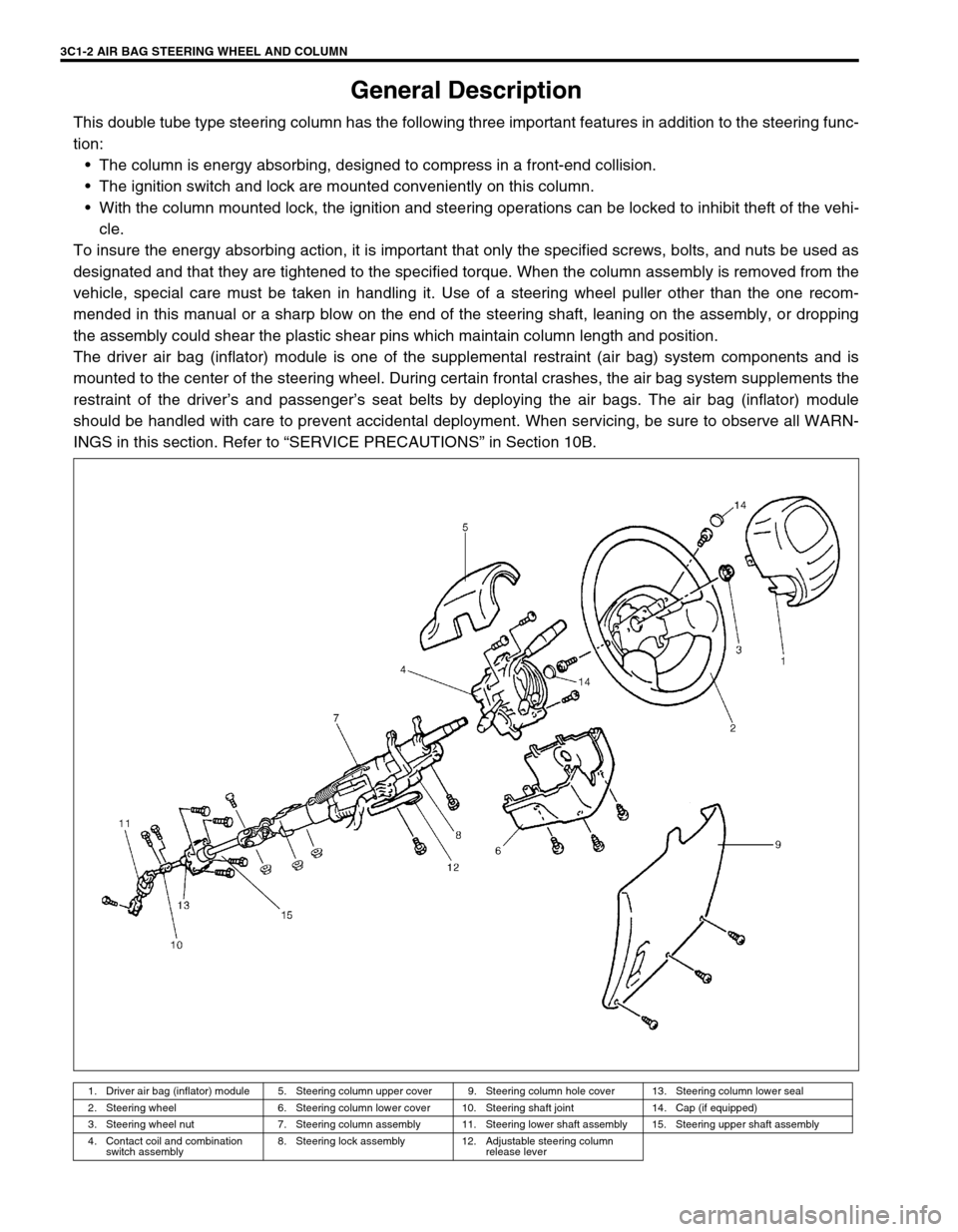
General Description
This double tube type steering column has the following three important features in addition to the steering func-
tion:
The column is energy absorbing, designed to compress in a front-end collision.
The ignition switch and lock are mounted conveniently on this column.
With the column mounted lock, the ignition and steering operations can be locked to inhibit theft of the vehi-
cle.
To insure the energy absorbing action, it is important that only the specified screws, bolts, and nuts be used as
designated and that they are tightened to the specified torque. When the column assembly is removed from the
vehicle, special care must be taken in handling it. Use of a steering wheel puller other than the one recom-
mended in this manual or a sharp blow on the end of the steering shaft, leaning on the assembly, or dropping
the assembly could shear the plastic shear pins which maintain column length and position.
The driver air bag (inflator) module is one of the supplemental restraint (air bag) system components and is
mounted to the center of the steering wheel. During certain frontal crashes, the air bag system supplements the
restraint of the driver’s and passenger’s seat belts by deploying the air bags. The air bag (inflator) module
should be handled with care to prevent accidental deployment. When servicing, be sure to observe all WARN-
INGS in this section. Refer to “SERVICE PRECAUTIONS” in Section 10B.
1. Driver air bag (inflator) module 5. Steering column upper cover 9. Steering column hole cover 13. Steering column lower seal
2. Steering wheel 6. Steering column lower cover 10. Steering shaft joint 14. Cap (if equipped)
3. Steering wheel nut 7. Steering column assembly 11. Steering lower shaft assembly 15. Steering upper shaft assembly
4. Contact coil and combination
switch assembly8. Steering lock assembly 12. Adjustable steering column
release lever
Page 79 of 656
3C1-4 AIR BAG STEERING WHEEL AND COLUMN
Steering Column
REMOVAL
1) Disconnect negative (–) cable at battery.
2) Disable air bag system. Refer to “DISABLING AIR BAG SYSTEM” under “SERVICE PRECAUTIONS” in
Section 10B.
3) Remove steering wheel and contact coil and combination switch assembly, if necessary. Refer to “STEER-
ING WHEEL” and “CONTACT COIL AND COMBINATION SWITCH ASSEMBLY” in this section.
Perform the following procedure if not removing steering wheel and/or combination switch.
a) Turn steering wheel so that vehicle’s front tires are at straight-ahead position.
b) Turn ignition switch to “LOCK” position and remove key.
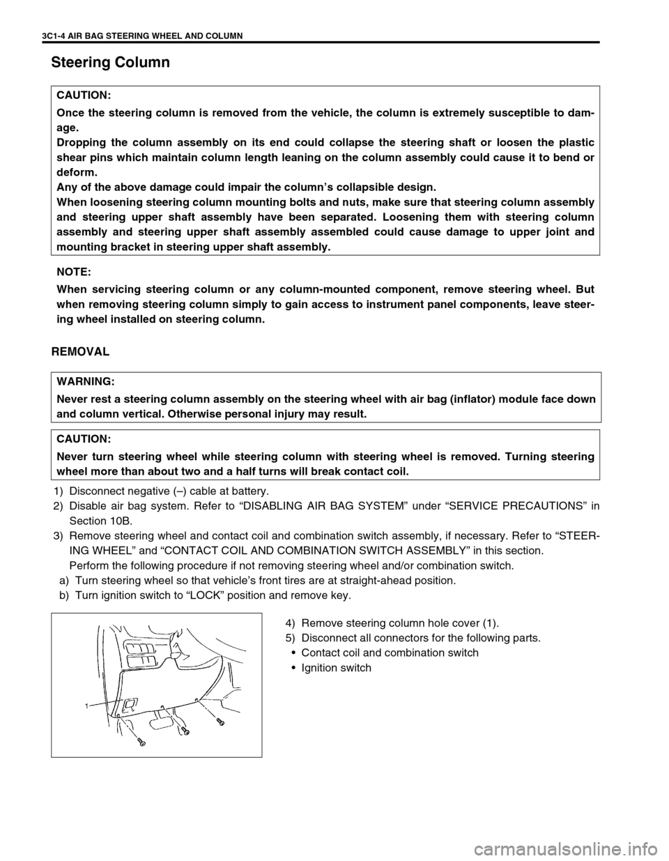
4) Remove steering column hole cover (1).
5) Disconnect all connectors for the following parts.
Contact coil and combination switch
Ignition switch CAUTION:
Once the steering column is removed from the vehicle, the column is extremely susceptible to dam-
age.
Dropping the column assembly on its end could collapse the steering shaft or loosen the plastic
shear pins which maintain column length leaning on the column assembly could cause it to bend or
deform.
Any of the above damage could impair the column’s collapsible design.
When loosening steering column mounting bolts and nuts, make sure that steering column assembly
and steering upper shaft assembly have been separated. Loosening them with steering column
assembly and steering upper shaft assembly assembled could cause damage to upper joint and
mounting bracket in steering upper shaft assembly.
NOTE:
When servicing steering column or any column-mounted component, remove steering wheel. But
when removing steering column simply to gain access to instrument panel components, leave steer-
ing wheel installed on steering column.
WARNING:
Never rest a steering column assembly on the steering wheel with air bag (inflator) module face down
and column vertical. Otherwise personal injury may result.
CAUTION:
Never turn steering wheel while steering column with steering wheel is removed. Turning steering
wheel more than about two and a half turns will break contact coil.
Page 80 of 656
AIR BAG STEERING WHEEL AND COLUMN 3C1-5
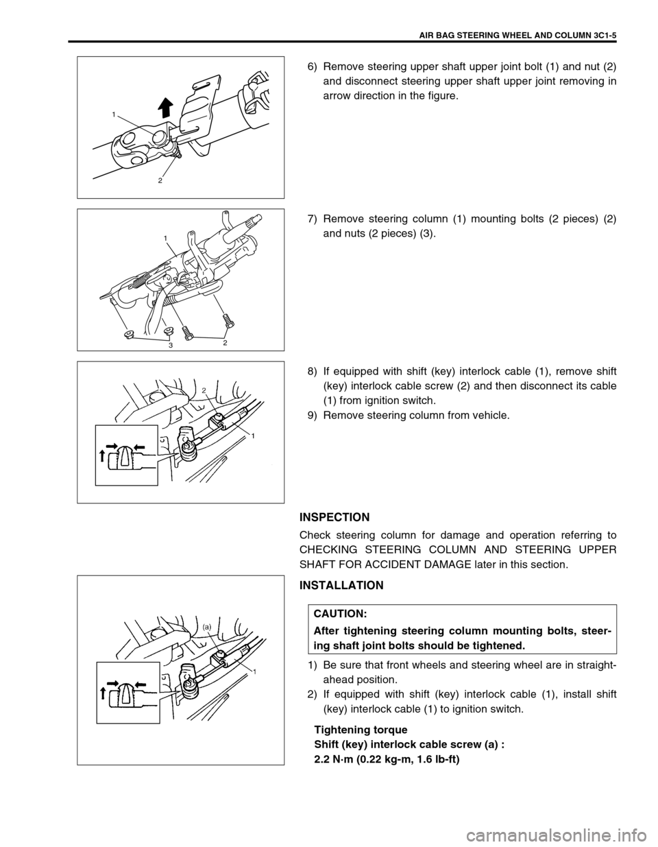
6) Remove steering upper shaft upper joint bolt (1) and nut (2)
and disconnect steering upper shaft upper joint removing in
arrow direction in the figure.
7) Remove steering column (1) mounting bolts (2 pieces) (2)
and nuts (2 pieces) (3).
8) If equipped with shift (key) interlock cable (1), remove shift
(key) interlock cable screw (2) and then disconnect its cable
(1) from ignition switch.
9) Remove steering column from vehicle.
INSPECTION
Check steering column for damage and operation referring to
CHECKING STEERING COLUMN AND STEERING UPPER
SHAFT FOR ACCIDENT DAMAGE later in this section.
INSTALLATION
1) Be sure that front wheels and steering wheel are in straight-
ahead position.
2) If equipped with shift (key) interlock cable (1), install shift
(key) interlock cable (1) to ignition switch.
Tightening torque
Shift (key) interlock cable screw (a) :
2.2 N·m (0.22 kg-m, 1.6 lb-ft)
1
2
1
32
CAUTION:
After tightening steering column mounting bolts, steer-
ing shaft joint bolts should be tightened.
Page 81 of 656
3C1-6 AIR BAG STEERING WHEEL AND COLUMN
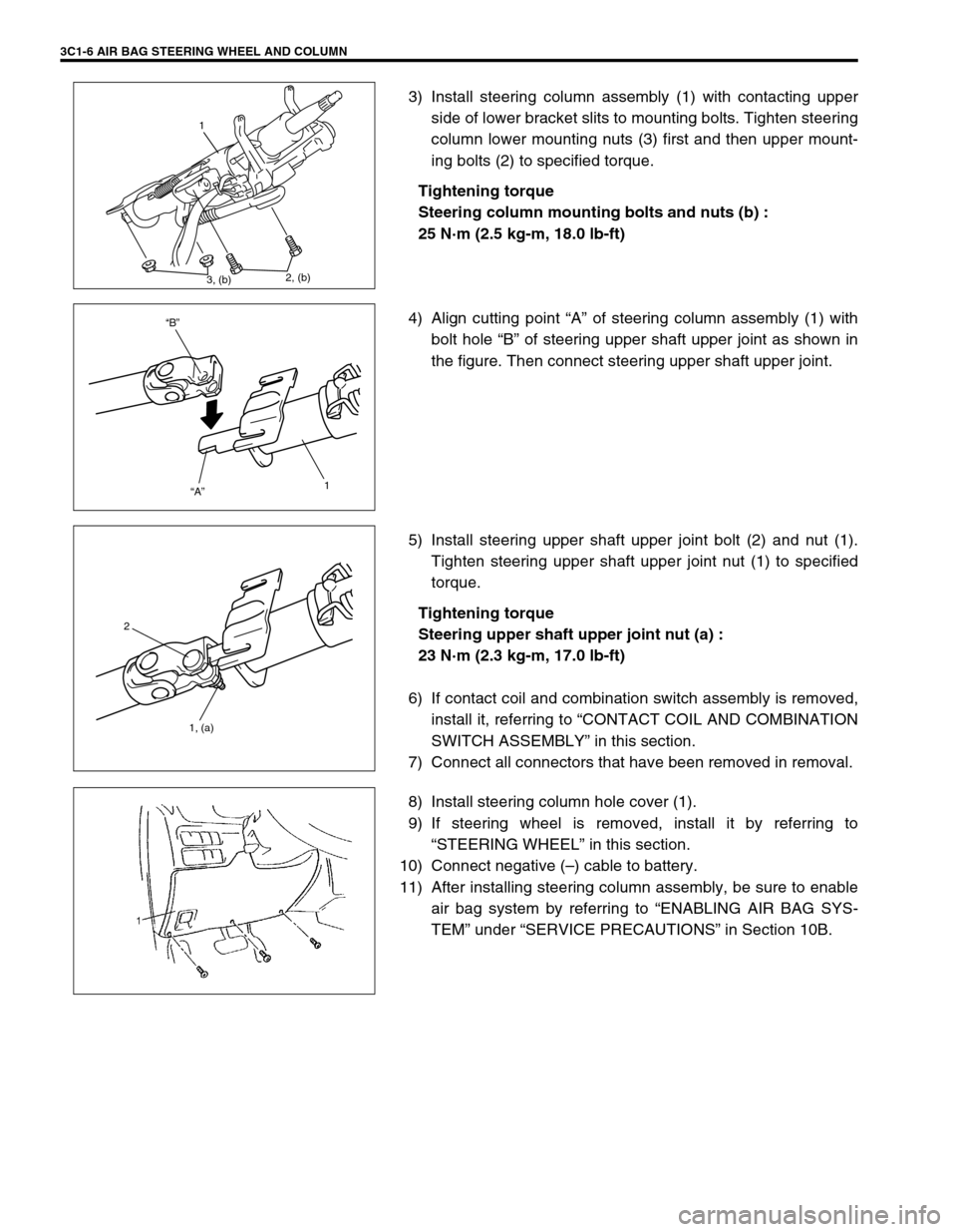
3) Install steering column assembly (1) with contacting upper
side of lower bracket slits to mounting bolts. Tighten steering
column lower mounting nuts (3) first and then upper mount-
ing bolts (2) to specified torque.
Tightening torque
Steering column mounting bolts and nuts (b) :
25 N·m (2.5 kg-m, 18.0 lb-ft)
4) Align cutting point “A” of steering column assembly (1) with
bolt hole “B” of steering upper shaft upper joint as shown in
the figure. Then connect steering upper shaft upper joint.
5) Install steering upper shaft upper joint bolt (2) and nut (1).
Tighten steering upper shaft upper joint nut (1) to specified
torque.
Tightening torque
Steering upper shaft upper joint nut (a) :
23 N·m (2.3 kg-m, 17.0 lb-ft)
6) If contact coil and combination switch assembly is removed,
install it, referring to “CONTACT COIL AND COMBINATION
SWITCH ASSEMBLY” in this section.
7) Connect all connectors that have been removed in removal.
8) Install steering column hole cover (1).
9) If steering wheel is removed, install it by referring to
“STEERING WHEEL” in this section.
10) Connect negative (–) cable to battery.
11) After installing steering column assembly, be sure to enable
air bag system by referring to “ENABLING AIR BAG SYS-
TEM” under “SERVICE PRECAUTIONS” in Section 10B.
1
3, (b)2, (b)
“B”
“A”
1
2
1, (a)
Page 82 of 656
AIR BAG STEERING WHEEL AND COLUMN 3C1-7
Steering Upper Shaft Assembly
REMOVAL
1) Turn steering wheel so that vehicle’s front tires are at
straight-ahead position.
2) Turn ignition switch to “LOCK” position and remove key.
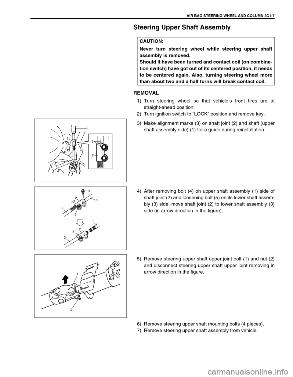
3) Make alignment marks (3) on shaft joint (2) and shaft (upper
shaft assembly side) (1) for a guide during reinstallation.
4) After removing bolt (4) on upper shaft assembly (1) side of
shaft joint (2) and loosening bolt (5) on its lower shaft assem-
bly (3) side, move shaft joint (2) to lower shaft assembly (3)
side (in arrow direction in the figure).
5) Remove steering upper shaft upper joint bolt (1) and nut (2)
and disconnect steering upper shaft upper joint removing in
arrow direction in the figure.
6) Remove steering upper shaft mounting bolts (4 pieces).
7) Remove steering upper shaft assembly from vehicle.CAUTION:
Never turn steering wheel while steering upper shaft
assembly is removed.
Should it have been turned and contact coil (on combina-
tion switch) have got out of its centered position, it needs
to be centered again. Also, turning steering wheel more
than about two and a half turns will break contact coil.
1
2