Page 10 of 656

GENERAL INFORMATION 0A-5
CAUTION:
Even when the accident was light enough not to cause air bags to activate, be sure to inspect sys-
tem parts and other related parts according to instructions under “REPAIR AND INSPECTION
REQUIRED AFTER AN ACCIDENT” in SECTION 10B.
When servicing parts other than air bag system, if shocks may be applied to air bag system compo-
nent parts, remove those parts beforehand.
When handling the air bag (inflator) modules (driver and passenger), forward sensors or SDM, be
careful not to drop it or apply an impact to it. If an excessive impact was applied (e.g., dropped from
a height of 91.4 cm (3 feet) or more), never attempt disassembly or repair but replace it with a new
one.
When grease, cleaning agent, oil, water, etc. has got onto air bag (inflator) modules (driver and pas-
senger), wipe off immediately with a dry cloth.
Air bag wire harness can be identified easily as it is covered with a yellow protection tube. Be very
careful when handling it.
When an open in air bag wire harness, damaged wire harness, connector or terminal is found,
replace wire harness, connectors and terminals as an assembly.
Do not apply power to the air bag system unless all components are connected or a diagnostic
chart requests it, as this will set a diagnostic trouble code.
Never use air bag system component parts from another vehicle.
When using electric welding, be sure to temporarily disable air bag system referring to “DIS-
ABLING AIR BAG SYSTEM” in SECTION 10B.
Never expose air bag system component parts directly to hot air (drying or baking the vehicle after
painting) or flames.
WARNING/CAUTION labels are attached on each part of air bag system components. Be sure to fol-
low the instructions.
After vehicle is completely repaired, perform “AIR BAG DIAGNOSTIC SYSTEM CHECK” in SEC-
TION 10B.
Page 66 of 656

AIR CONDITIONING (OPTIONAL) 1B-41
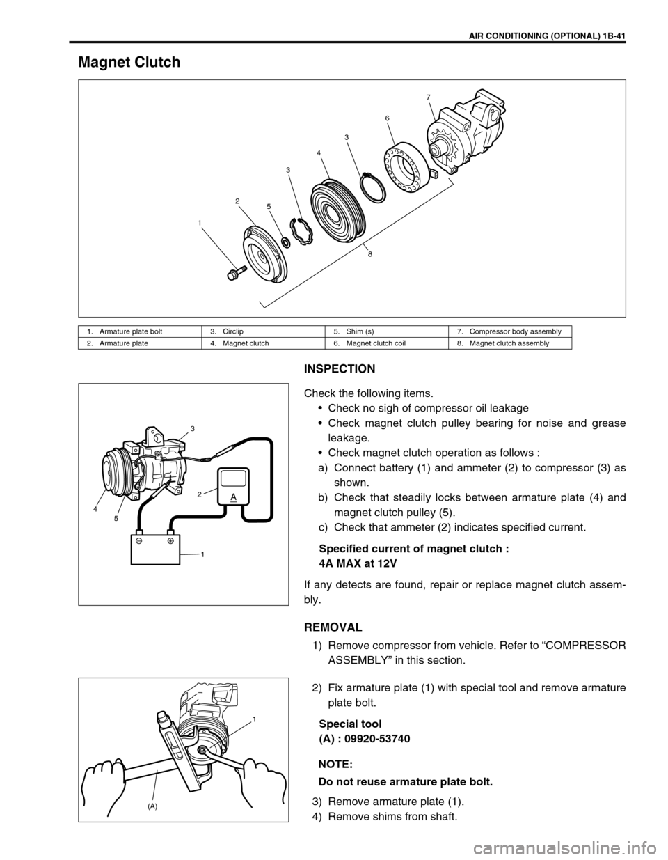
Magnet Clutch
INSPECTION
Check the following items.
Check no sigh of compressor oil leakage
Check magnet clutch pulley bearing for noise and grease
leakage.
Check magnet clutch operation as follows :
a) Connect battery (1) and ammeter (2) to compressor (3) as
shown.
b) Check that steadily locks between armature plate (4) and
magnet clutch pulley (5).
c) Check that ammeter (2) indicates specified current.
Specified current of magnet clutch :
4A MAX at 12V
If any detects are found, repair or replace magnet clutch assem-
bly.
REMOVAL
1) Remove compressor from vehicle. Refer to “COMPRESSOR
ASSEMBLY” in this section.
2) Fix armature plate (1) with special tool and remove armature
plate bolt.
Special tool
(A) : 09920-53740
3) Remove armature plate (1).
4) Remove shims from shaft.
1. Armature plate bolt 3. Circlip 5. Shim (s) 7. Compressor body assembly
2. Armature plate 4. Magnet clutch 6. Magnet clutch coil 8. Magnet clutch assembly
1234367
5
8
3
2
1 5 4
NOTE:
Do not reuse armature plate bolt.
(A)1
Page 93 of 656
3E-4 REAR SUSPENSION
5) Apply grease “A” to axle shaft inner oil seal lip as shown in
the figure.
“A” : Grease 99000-25010
6) Apply water tight sealant “B” to mating surfaces of brake
back plate and rear axle hub (2).
“B” : Water tight sealant 99000-31110
7) Install rear axle shaft to rear axle housing and tighten bear-
ing retainer nuts to specified torque.
Rear axle shaft length “L”
Left side : 700.5 mm (27.6 in.)
Right side : 769.5 mm (30.3 in.)
Tightening torque
Bearing retainer nut (a) : 50 N·m (5.0 kg-m, 36.5 lb-ft)
8) Tighten wheel speed sensor bolt to specified torque (if
equipped with ABS).
Tightening torque
Wheel speed sensor bolt (b) : 21 N·m (2.1 kg-m, 15.5 lb-ft)
9) Refill rear axle housing with new specified gear oil.
Refer to “MAINTENANCE SERVICE” in Section 7F.
10) Install brake drum. Refer to “BRAKE DRUM” in Section 5C.
1. Axle housing
NOTE:
When installing rear axle shaft, be careful not to cause
damage to oil seal lip in axle housing.
(b)
Page 94 of 656

REAR SUSPENSION 3E-5
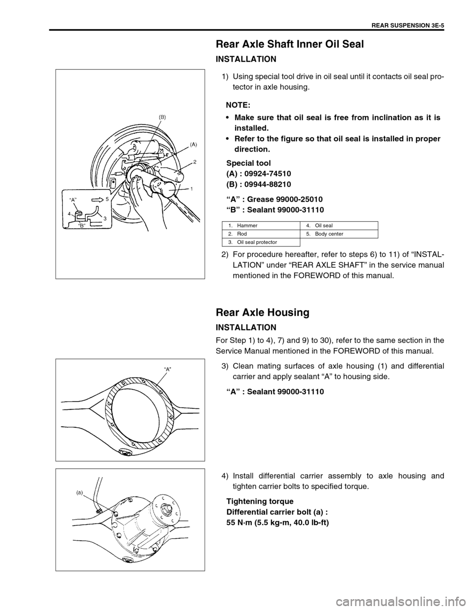
Rear Axle Shaft Inner Oil Seal
INSTALLATION
1) Using special tool drive in oil seal until it contacts oil seal pro-
tector in axle housing.
Special tool
(A) : 09924-74510
(B) : 09944-88210
“A” : Grease 99000-25010
“B” : Sealant 99000-31110
2) For procedure hereafter, refer to steps 6) to 11) of “INSTAL-
LATION” under “REAR AXLE SHAFT” in the service manual
mentioned in the FOREWORD of this manual.
Rear Axle Housing
INSTALLATION
For Step 1) to 4), 7) and 9) to 30), refer to the same section in the
Service Manual mentioned in the FOREWORD of this manual.
3) Clean mating surfaces of axle housing (1) and differential
carrier and apply sealant “A” to housing side.
“A” : Sealant 99000-31110
4) Install differential carrier assembly to axle housing and
tighten carrier bolts to specified torque.
Tightening torque
Differential carrier bolt (a) :
55 N·m (5.5 kg-m, 40.0 lb-ft) NOTE:
Make sure that oil seal is free from inclination as it is
installed.
Refer to the figure so that oil seal is installed in proper
direction.
1. Hammer 4. Oil seal
2. Rod 5. Body center
3. Oil seal protector
Page 95 of 656

3E-6 REAR SUSPENSION
5) Apply thread lock cement to thread of propeller shaft flange
bolt if reused. Install propeller shaft to joint flange aligning
match marks and torque flange nuts to specification.
“A” : Cement 99000-32110
Tightening torque
Propeller shaft nut (a) :
60 N·m (6.0 kg-m, 43.5 lb-ft)
Tightening Torque Specification
Required Service Material
Fastening partTightening torque
Nm kg-m lb-ft
Shock absorber nut 29 2.9 21.0
Shock absorber lower nut 85 8.5 61.5
Lower rod bolt and nut 100 10.0 72.5
Upper rod bolt and nut 100 10.0 72.5
Lateral rod bolt 100 10.0 72.5
Differential carrier bolt 55 5.5 40.0
Propeller shaft nut 60 6.0 43.5
Brake pipe flare nut 16 1.6 11.5
Bearing retainer nut 50 5.0 36.5
Differentiation gear oil filler & drain plug (filler plug) 50 5.0 36.5
Differentiation gear oil filler & drain plug (drain plug) 27 2.7 16.0
Wheel nut 100 10.0 72.5
Wheel speed sensor bolt 21 2.1 15.5
MaterialRecommended SUZUKI product
(Part Number)Use
Lithium grease SUZUKI SUPER GREASE A
(99000-25010)Oil seal lip
Brake fluid DOT 3Brake reservoir tank
Sealant SUZUKI BOND NO. 1215
(99000-31110)Joint seam of axle and brake back plate
Joint seam of bearing retainer and brake
back plate
Joint seam of differential carrier and axle
housing
Drain plug
Mating surface of oil seal and axle housing
Gear oil For gear oil information, refer to Section 7FDifferential gear (Rear axle housing)
Thread lock
cementTHREAD LOCK CEMENT SUPER 1322
(99000-32110)Rear propeller shaft flange bolts
Page 101 of 656

4A2-2 FRONT DRIVE SHAFT/SHAFT BEARING, OIL SEAL
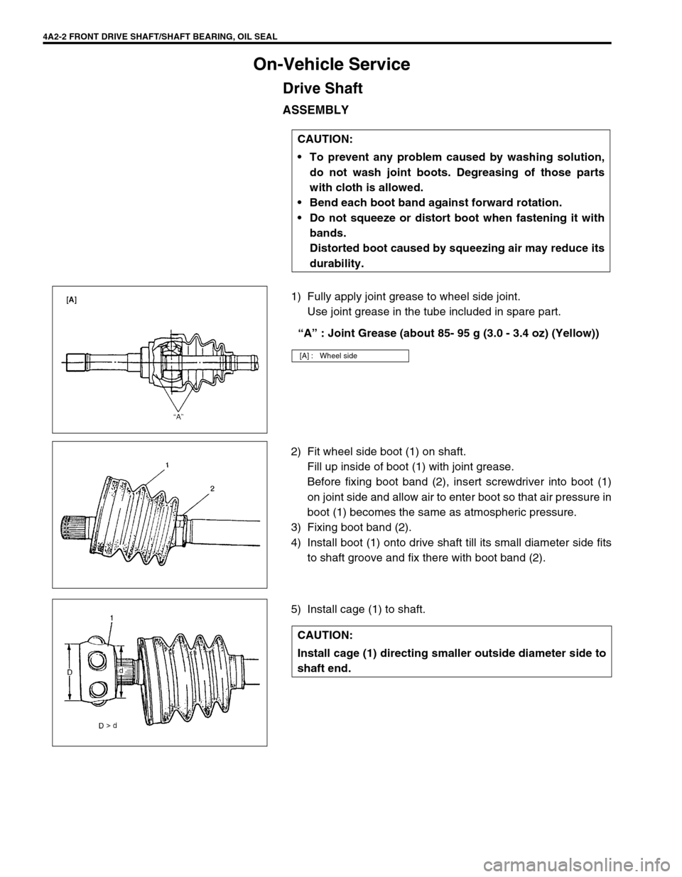
On-Vehicle Service
Drive Shaft
ASSEMBLY
1) Fully apply joint grease to wheel side joint.
Use joint grease in the tube included in spare part.
“A” : Joint Grease (about 85- 95 g (3.0 - 3.4 oz) (Yellow))
2) Fit wheel side boot (1) on shaft.
Fill up inside of boot (1) with joint grease.
Before fixing boot band (2), insert screwdriver into boot (1)
on joint side and allow air to enter boot so that air pressure in
boot (1) becomes the same as atmospheric pressure.
3) Fixing boot band (2).
4) Install boot (1) onto drive shaft till its small diameter side fits
to shaft groove and fix there with boot band (2).
5) Install cage (1) to shaft.CAUTION:
To prevent any problem caused by washing solution,
do not wash joint boots. Degreasing of those parts
with cloth is allowed.
Bend each boot band against forward rotation.
Do not squeeze or distort boot when fastening it with
bands.
Distorted boot caused by squeezing air may reduce its
durability.
[A] : Wheel side
CAUTION:
Install cage (1) directing smaller outside diameter side to
shaft end.
Page 102 of 656

FRONT DRIVE SHAFT/SHAFT BEARING, OIL SEAL 4A2-3
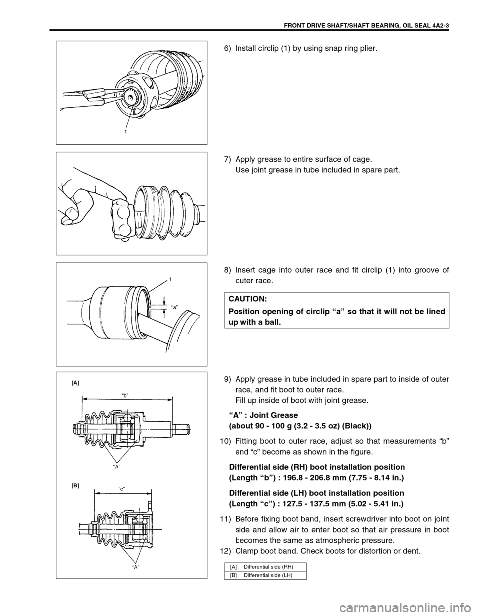
6) Install circlip (1) by using snap ring plier.
7) Apply grease to entire surface of cage.
Use joint grease in tube included in spare part.
8) Insert cage into outer race and fit circlip (1) into groove of
outer race.
9) Apply grease in tube included in spare part to inside of outer
race, and fit boot to outer race.
Fill up inside of boot with joint grease.
“A” : Joint Grease
(about 90 - 100 g (3.2 - 3.5 oz) (Black))
10) Fitting boot to outer race, adjust so that measurements “b”
and “c” become as shown in the figure.
Differential side (RH) boot installation position
(Length “b”) : 196.8 - 206.8 mm (7.75 - 8.14 in.)
Differential side (LH) boot installation position
(Length “c”) : 127.5 - 137.5 mm (5.02 - 5.41 in.)
11) Before fixing boot band, insert screwdriver into boot on joint
side and allow air to enter boot so that air pressure in boot
becomes the same as atmospheric pressure.
12) Clamp boot band. Check boots for distortion or dent.
CAUTION:
Position opening of circlip “a” so that it will not be lined
up with a ball.
[A] : Differential side (RH)
[B] : Differential side (LH)
Page 103 of 656
4A2-4 FRONT DRIVE SHAFT/SHAFT BEARING, OIL SEAL
Required Service Material
MaterialRecommended SUZUKI product
(Part Number)Use
Lithium grease SUZUKI SUPER GREASE A
(99000-25010)Drive shaft oil seal
Wheel spindle part of differential
side drive shaft (RH)
Sealant SEALING COMPOUND 366E
(99000-31090)Axle shaft drive flange