1999 SUZUKI GRAND VITARA IAC valve connector
[x] Cancel search: IAC valve connectorPage 334 of 656

ENGINE AND EMISSION CONTROL SYSTEM (SEQUENTIAL MULTIPORT FUEL INJECTION FOR H27 ENGINE) 6E2-1
6E2
SECTION 6E2
ENGINE AND EMISSION CONTROL SYSTEM
(SEQUENTIAL MULTIPORT FUEL INJECTION
FOR H27 ENGINE)
CONTENTS
General Description ..................................... 6E2-2
System Flow ............................................... 6E2-3
System Diagram ......................................... 6E2-4
Air Intake System ....................................... 6E2-6
Fuel Delivery System ................................. 6E2-7
Electronic Control System .......................... 6E2-8
Engine and Emission Control Input/Output
Table ........................................................ 6E2-12
Diagnosis .................................................... 6E2-12
On-Vehicle Service..................................... 6E2-13
General .................................................... 6E2-13
Accelerator Cable Adjustment .................. 6E2-14
A/T Throttle Cable Adjustment
(A/T Vehicle) ............................................ 6E2-14Idle Speed/Idle Air Control (IAC) Duty
Inspection................................................. 6E2-15
[Using SUZUKI scan tool] .................... 6E2-15
[Not using SUZUKI scan tool]
(vehicle with monitor connector) .......... 6E2-16
Idle mixture inspection/adjustment
(vehicle without heated oxygen sensor) 6E2-17
Air Intake System ..................................... 6E2-18
Throttle body ........................................ 6E2-18
Idle air control valve (IAC valve) .......... 6E2-21
Fast idle air valve ................................. 6E2-22
Fuel Delivery System ............................... 6E2-23
Fuel pressure inspection ...................... 6E2-23
Fuel pump ............................................ 6E2-24
Fuel pressure regulator ........................ 6E2-25 WARNING:
For vehicles equipped with Supplemental Restraint (Air Bag) System:
Service on and around the air bag system components or wiring must be performed only by an
authorized SUZUKI dealer. Refer to “Air Bag System Components and Wiring Location View” under
“General Description” in air bag system section in order to confirm whether you are performing ser-
vice on or near the air bag system components or wiring. Please observe all WARNINGS and “Ser-
vice Precautions” under “On-Vehicle Service” in air bag system section before performing service
on or around the air bag system components or wiring. Failure to follow WARNINGS could result in
unintentional activation of the system or could render the system inoperative. Either of these two
conditions may result in severe injury.
Technical service work must be started at least 90 seconds after the ignition switch is turned to the
“LOCK” position and the negative cable is disconnected from the battery. Otherwise, the system
may be activated by reserve energy in the Sensing and Diagnostic Module (SDM).
NOTE:
Whether following systems (parts) are used in the particular vehicle or not depends on specifications.
Be sure to bear this in mind when performing service work.
Monitor connector
CKP sensor
MAP sensor
EGR valve
Heated oxygen sensor or CO adjusting resistor
Three way catalytic converter, Warm-up three way catalytic converter
Page 345 of 656

6E2-12 ENGINE AND EMISSION CONTROL SYSTEM (SEQUENTIAL MULTIPORT FUEL INJECTION FOR H27 ENGINE)
Engine and Emission Control Input/Output Table
Diagnosis
Refer to Section 6-1.
Ignition coil with igniter
HO2S heater control
Input
Output Function
Main relay control
Fuel pump control
Injection control
Ignition control
MIL control Idle air control
EVAP purge control
EGR control
A/C control
A/C condensor fan
controlMain relay
Fuel pump relay
Injectors
MIL
EVAP canister purge
valve IAC valve
EGR valve (if equipped)
HO2S (if equipped)
A/C amplifier
(if equipped)
A/C condensor fan
relay (if equipped)
CMP sensor
MAF sensor
TP sensor
ECT sensor
IAT sensor
HO2S (sensor 1)(if equipped)
VSS
Blower fan switch
Rear defogger switch
PSP switch
Ignition switch
Starter switch
A/C amplifier (if equipped)
TR switch (A/T VEHICLE)
Light switch
Knock sensor
CO adjusting resistor (if equipped)
Test swich terminal (Vehicle with monitor connector)
Diag. swich terminal (Vehicle with monitor connector)
Brake switch (A/T VEHICLE)
ABS control module
Page 346 of 656

ENGINE AND EMISSION CONTROL SYSTEM (SEQUENTIAL MULTIPORT FUEL INJECTION FOR H27 ENGINE) 6E2-13
On-Vehicle Service
General
When hoses are disconnected and system components are removed for service, reinstall components properly,
and route and connect hoses correctly after service. Refer to figure on previous page for proper routing of
hoses.
1. Brake booster hose pipe 8. EGR pipe (if equipped) 15. EVAP canister
2. Vacuum hose for fuel pressure regulator 9. Exhaust manifold 16. Tank pressure control valve
3. Fuel pressure regulator 10. Heated oxygen sensor 17. To fuel tank
4. MAP sensor (if equipped) 11. EGR valve (if equipped) 18. Cap
5. Engine coolant hose 12. PCV hose [A]: Vehicle without monitor connector
6. EVAP canister purge valve 13. IAC valve [B]: Vehicle with monitor connector
7. Breather hose 14. IAC hose
Page 352 of 656

ENGINE AND EMISSION CONTROL SYSTEM (SEQUENTIAL MULTIPORT FUEL INJECTION FOR H27 ENGINE) 6E2-19
6) Remove surge tank cover.
Remove intake air pipe (1) and surge tank pipe (2).
7) Disconnect connectors of TP sensor and IAC valve.
8) Disconnect ground wire at connector.
9) Remove clamp bracket (1) and harness clamps from intake
collector.
10) Disconnect connectors of EVAP canister purge valve (1),
MAP sensor and EGR valve (5).
11) Disconnect PCV valve (6) from cylinder head with hose con-
nected, breather hose (3) from cylinder head and EVAP can-
ister purge valve hose (2).
12) Detach EGR pipe (4) from intake air collector.
13) Remove throttle body (3) and intake collector (2) from intake
manifold (1).
14) Disconnect hoses of PCV from throttle body.
15) Remove throttle body from intake collector.
NOTE:
TP sensor (4), or other components containing rubber
must not be placed in a solvent or cleaner bath. A
chemical reaction will cause these parts to swell,
harden or get distorted.
Don’t put drills or wires into passages for cleaning. It
causes damages in passages.
Page 353 of 656

6E2-20 ENGINE AND EMISSION CONTROL SYSTEM (SEQUENTIAL MULTIPORT FUEL INJECTION FOR H27 ENGINE)
CLEANING
Clean throttle body bore and bypass air passages (1) by blowing
compressed air.
INSTALLATION
1) Clean mating surfaces and install throttle body gasket to
intake collector (1) with new gasket (2).
2) Install throttle body to intake collector and tighten bolts.
3) Connect PCV hose.
4) Install throttle body and intake collector to intake manifold
with new intake collector gaskets.
5) Install EGR pipe with new gaskets.
6) Connect breather hose and EVAP canister purge valve hose
and install PCV valve to cylinder head.
7) Connect connectors of EVAP canister purge valve, MAP
sensor and EGR valve.
Fix wire harness with clamps.
8) Install clamp bracket to intake collector.
9) Connect ground wire connector.
10) Connect connectors of TP sensor, ground and IAC valve.
11) Install surge tank pipe to intake manifold with new gaskets
and intake air pipe to throttle body. Install surge tank cover.
12) Connect engine coolant hoses to throttle body.
13) Connect accelerator cable and A/T throttle cable (A/T).CAUTION:
Do not blow compressed air through bypass air pas-
sage with IAC valve installed to throttle body. This will
cause IAC valve to malfunction.
TP sensor, idle air control valve or other components
containing rubber must not be places in a solvent or
cleaner bath.
A chemical reaction will cause these parts to swell,
harden or get distorted.
Page 354 of 656

ENGINE AND EMISSION CONTROL SYSTEM (SEQUENTIAL MULTIPORT FUEL INJECTION FOR H27 ENGINE) 6E2-21
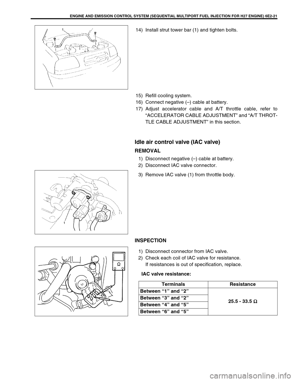
14) Install strut tower bar (1) and tighten bolts.
15) Refill cooling system.
16) Connect negative (–) cable at battery.
17) Adjust accelerator cable and A/T throttle cable, refer to
“ACCELERATOR CABLE ADJUSTMENT” and “A/T THROT-
TLE CABLE ADJUSTMENT” in this section.
Idle air control valve (IAC valve)
REMOVAL
1) Disconnect negative (–) cable at battery.
2) Disconnect IAC valve connector.
3) Remove IAC valve (1) from throttle body.
INSPECTION
1) Disconnect connector from IAC valve.
2) Check each coil of IAC valve for resistance.
If resistances is out of specification, replace.
IAC valve resistance:
Terminals Resistance
Between “1” and “2”
25.5 - 33.5 Ω
ΩΩ Ω Between “3” and “2”
Between “4” and “5”
Between “6” and “5”
Page 355 of 656

6E2-22 ENGINE AND EMISSION CONTROL SYSTEM (SEQUENTIAL MULTIPORT FUEL INJECTION FOR H27 ENGINE)
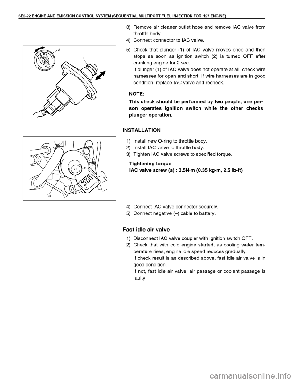
3) Remove air cleaner outlet hose and remove IAC valve from
throttle body.
4) Connect connector to IAC valve.
5) Check that plunger (1) of IAC valve moves once and then
stops as soon as ignition switch (2) is turned OFF after
cranking engine for 2 sec.
If plunger (1) of IAC valve does not operate at all, check wire
harnesses for open and short. If wire harnesses are in good
condition, replace IAC valve and recheck.
INSTALLATION
1) Install new O-ring to throttle body.
2) Install IAC valve to throttle body.
3) Tighten IAC valve screws to specified torque.
Tightening torque
IAC valve screw (a) : 3.5N·m (0.35 kg-m, 2.5 lb-ft)
4) Connect IAC valve connector securely.
5) Connect negative (–) cable to battery.
Fast idle air valve
1) Disconnect IAC valve coupler with ignition switch OFF.
2) Check that with cold engine started, as cooling water tem-
perature rises, engine idle speed reduces gradually.
If check result is as described above, fast idle air valve is in
good condition.
If not, fast idle air valve, air passage or coolant passage is
faulty. NOTE:
This check should be performed by two people, one per-
son operates ignition switch while the other checks
plunger operation.