1999 SUZUKI GRAND VITARA fuel tank
[x] Cancel search: fuel tankPage 15 of 656

0B-2 MAINTENANCE AND LUBRICATION
Maintenance Schedule
Maintenance Schedule under Normal Driving Conditions
NOTE:
This interval should be judged by odometer reading or months, whichever comes first.
This table includes service as scheduled up to 90,000 km (54,000 miles) mileage. Beyond 90,000 km
(54,000 miles), carry out the same services at the same intervals respectively.
IntervalKm (× 1,000) 15 30 45 60 75 90
Miles (× 1,000) 9 18 27 36 45 54
Months 12 24 36 48 60 72
ENGINE
1-1. Drive belt V-rib belt (Flat type)––I––R
1-4. Engine oil and oil filter R R R R R R
1-5. Engine coolant––R––R
1-6. Exhaust system–I–I–I
IGNITION SYSTEM
2-1. Spark plugs When
unleaded
fuel is usedVehicle without
HO2SNickel plug –R–R–R
Iridium plug–––R––
Vehicle with
HO2SNickel plug ––R––R
Iridium plug Replace every 105,000 km or
63,000 miles
When leaded fuel is used, refer to “MAINTENANCE RECOMMENDED UNDER
SERVER DRIVING CONDITIONS” in this section.
FUEL SYSTEM
3-1. Air cleaner filter I I R I I R
3-2. Fuel lines and connections–I–I–I
3-3. Fuel filter Replace every 105,000 km or
63,000 miles
3-4. Fuel tank––I––I
EMISSION CONTROL SYSTEM
4-1. Crankcase ventilation hoses and connections (Vehicle without
HO2S)––I––I
4-2. PCV valve Vehicle without HO2S––I––I
Vehicle with HO2S–––––I
4-3. Fuel evaporative emission con-
trol systemVehicle without HO2S–I–I–I
Vehicle with HO2S–––––I
NOTE:
“R”: Replace or change
“I”: Inspect and correct, replace or lubricate if necessary
For Sweden, item 2-1, 4-2 and 4-3 should be performed by odometer reading only.
For Item 2-1. Nickel spark plugs, replace every 50,000 km if the local law requires.
Nickel spark plug: BKR6E-11 or K20PR-U11
Iridium spark plug: IFR5J11 or SK16PR11
Page 56 of 656

AIR CONDITIONING (OPTIONAL) 1B-31
INSPECTION
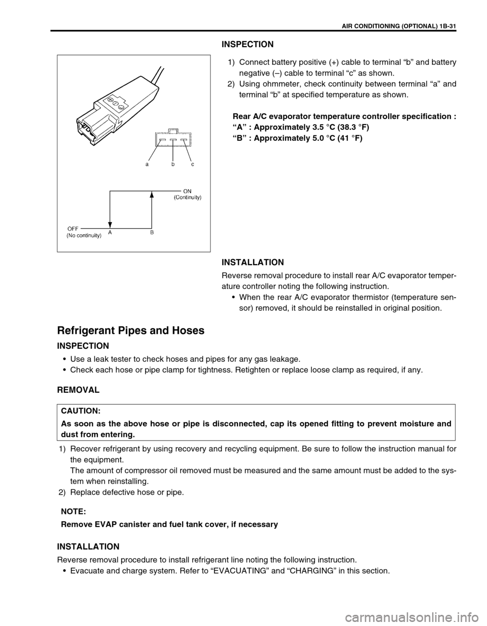
1) Connect battery positive (+) cable to terminal “b” and battery
negative (–) cable to terminal “c” as shown.
2) Using ohmmeter, check continuity between terminal “a” and
terminal “b” at specified temperature as shown.
Rear A/C evaporator temperature controller specification :
“A” : Approximately 3.5 °C (38.3 °F)
“B” : Approximately 5.0 °C (41 °F)
INSTALLATION
Reverse removal procedure to install rear A/C evaporator temper-
ature controller noting the following instruction.
When the rear A/C evaporator thermistor (temperature sen-
sor) removed, it should be reinstalled in original position.
Refrigerant Pipes and Hoses
INSPECTION
Use a leak tester to check hoses and pipes for any gas leakage.
Check each hose or pipe clamp for tightness. Retighten or replace loose clamp as required, if any.
REMOVAL
1) Recover refrigerant by using recovery and recycling equipment. Be sure to follow the instruction manual for
the equipment.
The amount of compressor oil removed must be measured and the same amount must be added to the sys-
tem when reinstalling.
2) Replace defective hose or pipe.
INSTALLATION
Reverse removal procedure to install refrigerant line noting the following instruction.
Evacuate and charge system. Refer to “EVACUATING” and “CHARGING” in this section.
CAUTION:
As soon as the above hose or pipe is disconnected, cap its opened fitting to prevent moisture and
dust from entering.
NOTE:
Remove EVAP canister and fuel tank cover, if necessary
Page 166 of 656

ENGINE GENERAL INFORMATION AND DIAGNOSIS (H27 ENGINE) 6-1-5
Fuel Pressure Relief Procedure
After making sure that engine is cold, relief fuel pressure as fol-
lows.
1) Place transmission gear shift lever in “Neutral” (shift selector
lever to “P” range for A/T vehicle), set parking brake, and
block drive wheels.
2) Remove fuel pump relay (1) from its connector.
3) Remove fuel filler cap to release fuel vapor pressure in fuel
tank and then reinstall it.
4) Start engine and run it till it stops for lack of fuel. Repeat
cranking engine 2 – 3 times of about 3 seconds each time to
dissipate fuel pressure in lines. Fuel connections are now
safe for servicing.
5) Upon completion of servicing, install fuel pump relay to relay
box.
Fuel Leakage Check Procedure
After performing any service on fuel system, check to make sure
that there are no fuel leakages as follows.
1) Turn ON ignition switch for 3 seconds (to operate fuel pump)
and then turn it OFF.
Repeat this (ON and OFF) 3 or 4 times and apply fuel pres-
sure to fuel line (till fuel pressure is felt by hand placed on
fuel return hose).
2) In this state, check to see that there are no fuel leakages
from any part of fuel system. CAUTION:
This work must not be done when engine is hot. If done
so, it may cause adverse effect to catalyst.
[A] : Left hand steering vehicle
[B] : Right hand steering vehicle
2. Fuse box
Page 175 of 656

6-1-14 ENGINE GENERAL INFORMATION AND DIAGNOSIS (H27 ENGINE)
STEP 6. AND 7. RECHECKING AND RECORD OF DTC
Refer to “DTC Check” in this section for checking procedure.
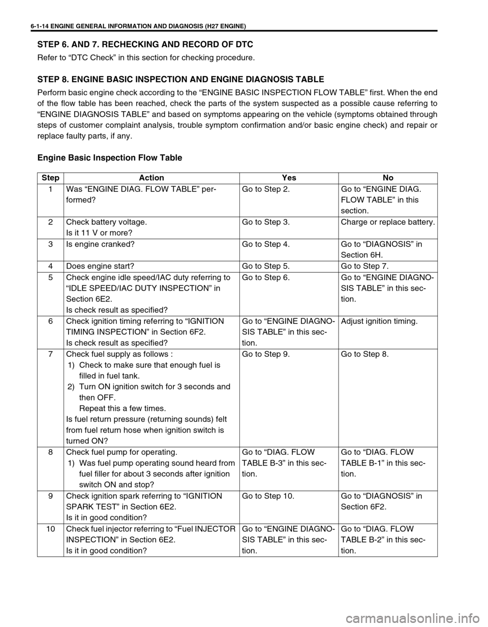
STEP 8. ENGINE BASIC INSPECTION AND ENGINE DIAGNOSIS TABLE
Perform basic engine check according to the “ENGINE BASIC INSPECTION FLOW TABLE” first. When the end
of the flow table has been reached, check the parts of the system suspected as a possible cause referring to
“ENGINE DIAGNOSIS TABLE” and based on symptoms appearing on the vehicle (symptoms obtained through
steps of customer complaint analysis, trouble symptom confirmation and/or basic engine check) and repair or
replace faulty parts, if any.
Engine Basic Inspection Flow Table
Step Action Yes No
1 Was “ENGINE DIAG. FLOW TABLE” per-
formed?Go to Step 2. Go to “ENGINE DIAG.
FLOW TABLE” in this
section.
2 Check battery voltage.
Is it 11 V or more?Go to Step 3. Charge or replace battery.
3 Is engine cranked? Go to Step 4. Go to “DIAGNOSIS” in
Section 6H.
4 Does engine start? Go to Step 5. Go to Step 7.
5 Check engine idle speed/IAC duty referring to
“IDLE SPEED/IAC DUTY INSPECTION” in
Section 6E2.
Is check result as specified?Go to Step 6. Go to “ENGINE DIAGNO-
SIS TABLE” in this sec-
tion.
6 Check ignition timing referring to “IGNITION
TIMING INSPECTION” in Section 6F2.
Is check result as specified?Go to “ENGINE DIAGNO-
SIS TABLE” in this sec-
tion.Adjust ignition timing.
7 Check fuel supply as follows :
1) Check to make sure that enough fuel is
filled in fuel tank.
2) Turn ON ignition switch for 3 seconds and
then OFF.
Repeat this a few times.
Is fuel return pressure (returning sounds) felt
from fuel return hose when ignition switch is
turned ON?Go to Step 9. Go to Step 8.
8 Check fuel pump for operating.
1) Was fuel pump operating sound heard from
fuel filler for about 3 seconds after ignition
switch ON and stop?Go to “DIAG. FLOW
TABLE B-3” in this sec-
tion.Go to “DIAG. FLOW
TABLE B-1” in this sec-
tion.
9 Check ignition spark referring to “IGNITION
SPARK TEST” in Section 6E2.
Is it in good condition?Go to Step 10. Go to “DIAGNOSIS” in
Section 6F2.
10 Check fuel injector referring to “Fuel INJECTOR
INSPECTION” in Section 6E2.
Is it in good condition?Go to “ENGINE DIAGNO-
SIS TABLE” in this sec-
tion.Go to “DIAG. FLOW
TABLE B-2” in this sec-
tion.
Page 187 of 656

6-1-26 ENGINE GENERAL INFORMATION AND DIAGNOSIS (H27 ENGINE)
PNP SIGNAL (Transmis-
sion Range Switch) (for 4-
A/T)With ignition switch ON, selector lever in “P”
or “N” positionP/N Range
✱
With ignition switch ON, selector lever in “R”,
“D”, “2” or “L” positionD Range
FUEL TANK LEVEL Ignition switch ON 0 – 100 %✱
ELECTRIC LOAD Ignition ON, small light OFF OFF✱
Ignition switch ON, small light ON ON✱
VSS (Vehicle speed sen-
sor) (for 4-A/T)At stop.
0 km/h 0 MPH✱
GEAR POSITION (for 4-
A/T)Ignition switch ON, selector lever is shifted at
“R”, “D”, “2” or “L” range and vehicle stops.1st✱
THROT POS LEVEL
(Throttle position level for
4-A/T)“0” (about idle position), “1”,“2”,“3”,“4”,“5”,“6” or “7” (about full open)
appears according to throttle valve opening.✱
SHIFT SOL #1 (A)
CON (Shift solenoid #1
command signal)
MON (Shift solenoid #1
monitor) (for 4-A/T)Ignition switch ON
Selector lever is shifted at “P”, “R”, “N”, “D”,
“2” or “L” range.
Vehicle stops.ON✱
SHIFT SOL #2 (B)
CON (Shift solenoid #2
command signal)
MON (Shift solenoid #2
monitor) (for 4-A/T)Ignition switch ON
Selector lever is shifted at “P”, “R”, “N”, “D”,
“2” or “L” range.
Vehicle stops.OFF✱
TCC SOL (for 4-A/T)
CON (Torque converter
clutch solenoid command
signal)
MON (Torque converter
clutch solenoid monitor)Ignition switch ON
Selector lever is shifted at “P”, “R”, “N”, “D”,
“2” or “L” range.
Vehicle stops.OFF✱
TRANS RANGE
(for 4-A/T)Ignition switch ON, selector lever is at “P”,
“R”, “N”, “D”, “2” or “L” range.P, R, N, D, 2 or L✱
BRAKE SW
(Brake, stop lamp, switch)
(for 4-A/T)Ignition switch ON, Brake pedal is released. OFF
✱
Ignition switch ON, Brake pedal is
depressed.ON
O/D OFF SW
(Overdrive cut switch)Ignition switch ON, Overdrive cut switch OFF OFF
✱
Ignition switch ON, Overdrive cut switch ON ON
MODE SELECT SW
(Power/Normal change
switch) (for 4-A/T)Ignition switch ON, P/N change switch is at
normal position.NORMAL
✱
Ignition switch ON, P/N change switch is at
power position.POWER
4WD-L SW
(4WD low switch)Ignition switch ON, Transfer lever is shifted
at “4H” or “2H” position.OFF
✱
Ignition switch ON, Transfer lever is shifted
at “4L” position.ON SCAN TOOL DATA CONDITIONNORMAL CONDITION/
REFERENCE VALUEOTHER
Page 190 of 656

ENGINE GENERAL INFORMATION AND DIAGNOSIS (H27 ENGINE) 6-1-29
EGR VALVE (%)
This parameter indicates opening rate of EGR valve which controls the amount of EGR flow.
A/C SWITCH (ON/OFF)
ON : Command for operation being output from A/C amplifier to compressor.
OFF : Command for operation not being output.
PSP SWITCH (ON/OFF)
ON : PSP switch detects P/S operation. (high P/S pressure)
OFF : PSP switch not detects P/S operation.
PNP SIGNAL (Transmission Range Switch, P/N or D range)
Whether the transmission range switch (P/N position switch) at P or N range or at R, D, 2 or L range is displayed.
If at P or N range, “P/N range” is displayed and if at R, D, 2 or L range, “D range” is displayed.
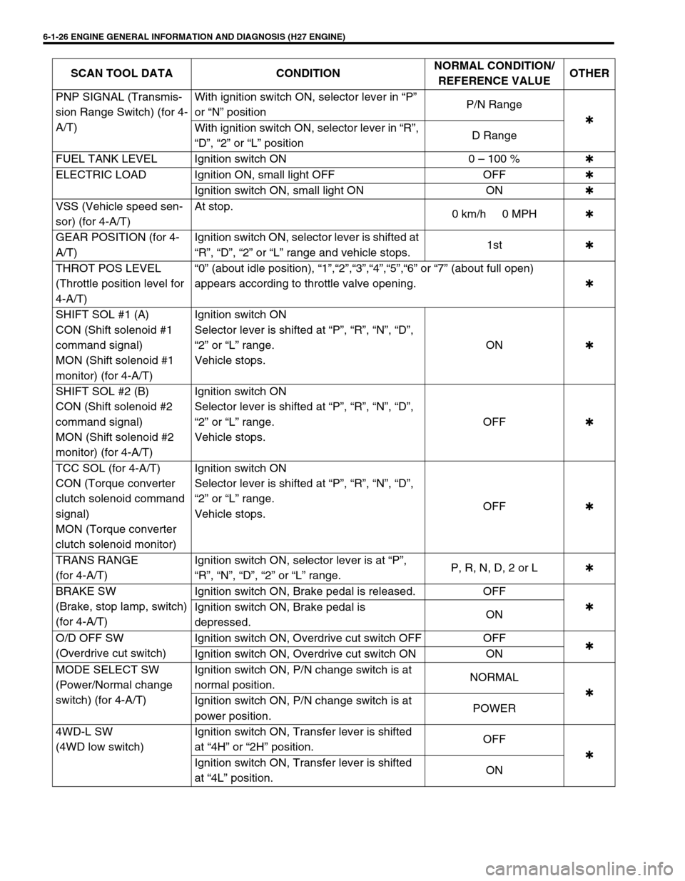
FUEL TANK LEVEL (%)
This parameter indicates approximate fuel level in the fuel tank. As the detectable range of the fuel level sensor
is set as 0 to 100 %, however, with some models whose fuel tank capacity is smaller, the indicated fuel level may
be only 70 % even when the fuel tank is full.
ELECTRIC LOAD (ON/OFF)
ON : Small light switch ON or rear window defogger switch ON.
OFF : Small light switch OFF and rear window defogger switch OFF.
VSS (4-A/T) (km/h, MPH)
It is computed by using pulse signals from vehicle speed sensor on 4-speed automatic transmission.
THROT POS LEVEL (Throttle Position Level For 4-A/T, “0”, “1”, “2”, “3”, “4”,“5”,“6” or “7”)
This parameter indicates which level (zone) the throttle valve opening is in.
The throttle opening is divided into 8 levels (zones) from “0” (about idle position) to “7” (about full open) and sig-
nals are assigned to each opening level (zone). PCM controls the automatic gear change of the automatic trans-
mission by using these signals according to the signal from the TP sensor.
GEAR POSITION (1ST, 2ND, 3RD or 4TH)
The gear position is determined on the basis of the command state signals generated from PCM to shift sole-
noids A and B (#1 and #2) and displayed as shown in the table below.
SHIFT SOL #1 CON/MON (Shift Solenoid #1, A Command/monitor, ON/OFF)
CON-ON : ON command being output to shift solenoid #1, A.
CON-OFF : ON command not being output.
MON-ON : Electricity being passed to shift solenoid #1, A.
MON-OFF : Electricity not being passed.SHIFT SOLENOID-A SHIFT SOLENOID-B
DISPLAY1ST ON OFF
2ND ON ON
3RD OFF ON
4TH OFF OFF
Page 265 of 656

6-1-104 ENGINE GENERAL INFORMATION AND DIAGNOSIS (H27 ENGINE)
TROUBLESHOOTING
Step Action Yes No
1Was “ENGINE DIAG. FLOW TABLE” per-
formed?Go to Step 2. Go to “ENGINE DIAG.
FLOW TABLE” in this
section.
2 Does fuel level meter in combination meter indi-
cate “E” (Empty)?Replenish fuel tank with
fuel and go to Step 3.Go to Step 3.
3 Check fuel level sensor and its circuit:
1) Check voltage between terminal E61-28 and
ground with ignition switch ON.
Is it about 7.1 V or more?Go to Step 4. Intermittent trouble or
faulty ECM (PCM).
Check for intermittent
referring to “INTERMIT-
TENT AND POOR CON-
NECTION” in Section
0A.
4 Is voltage in Step 3 “9 – 14 V”?“BLU/WHT” wire shorted
to power circuit or fuel
level meter malfunction.Go to Step 5.
5 Check Fuel Level Sensor:
1) Turn ignition switch OFF and disconnect fuel
level sensor connector (L15 – R01).
2) Check for proper connection to fuel level
sensor at L15-4 and L15-3 terminals.
3) If OK, then check resistance between R01-4
and R01-3 terminals. (Refer to “FUEL LEVEL
GAUGE (SENDER GAUGE)” in Section 8C.)
Is value close to one of above values indicated?“BLU/WHT” or “BLK/YEL”
circuit open.
If wire and connection are
OK, substitute a known-
good ECM (PCM) and
recheck.Check “BLU/WHT” and
“BLK/YEL” wires
between R01 and R02
connections.
If OK, replace fuel level
sensor.
Page 281 of 656

6-1-120 ENGINE GENERAL INFORMATION AND DIAGNOSIS (H27 ENGINE)
3 1) Start engine and warm it up to normal oper-
ating temperature.
2) Keep it running at specified idle speed.
Is fuel pressure then within 210 – 260 kPa
(2.1 – 2.6 kg/cm
2, 29.8 – 37.0 psi)?Normal fuel pressure. Clogged vacuum passage
for fuel pressure regula-
tor or faulty fuel pressure
regulator.
4 Is there fuel leakage from fuel feed line hose,
pipe or joint?Fuel leakage from hose,
pipe or joint.Go to Step 10.
5 Was fuel pressure higher than spec. in Step 1? Go to Step 6. Go to Step 7.
6 1) Disconnect fuel return hose from fuel pipe
and connect new hose to it.
2) Put the other end of new return hose into
approved gasoline container.
3) Operate fuel pump.
Is specified fuel pressure obtained then?Restricted fuel return
hose or pipe.Faulty fuel pressure regu-
lator.
7 Was no fuel pressure applied in Step 1? Go to Step 8. Go to Step 9.
(Low pressure is mea-
sured.)
8 With fuel pump operated and fuel return hose
blocked by pinching it, is fuel pressure applied?Faulty fuel pressure regu-
lator.Shortage of fuel or fuel
pump or its circuit defec-
tive (Refer to “TABLE B-
1”).
9 1) Operate fuel pump.
2) With fuel return hose blocked by pinching it,
check fuel pressure.
Is it 450 kPa (4.5 kg/cm
2, 64.0 psi) or more?Faulty fuel pressure regu-
lator.Clogged fuel filter,
restricted fuel feed hose
or pipe, faulty fuel pump
or fuel leakage from hose
connection in fuel tank.
10 1) Disconnect fuel return hose from fuel pipe
and connect new hose to it.
2) Put the other end of new return hose into
approved gasoline container.
3) Check again if specified fuel pressure is
retained.
While doing so, does fuel come out return
hose?Faulty fuel pressure regu-
lator.Fuel leakage from injec-
tor, faulty fuel pump
(faulty check valve in fuel
pump) or fuel leakage
from fuel pressure regula-
tor diaphragm. Step Action Yes No