1999 SUZUKI GRAND VITARA fuel tank
[x] Cancel search: fuel tankPage 340 of 656

ENGINE AND EMISSION CONTROL SYSTEM (SEQUENTIAL MULTIPORT FUEL INJECTION FOR H27 ENGINE) 6E2-7
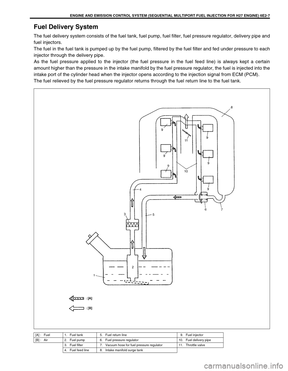
Fuel Delivery System
The fuel delivery system consists of the fuel tank, fuel pump, fuel filter, fuel pressure regulator, delivery pipe and
fuel injectors.
The fuel in the fuel tank is pumped up by the fuel pump, filtered by the fuel filter and fed under pressure to each
injector through the delivery pipe.
As the fuel pressure applied to the injector (the fuel pressure in the fuel feed line) is always kept a certain
amount higher than the pressure in the intake manifold by the fuel pressure regulator, the fuel is injected into the
intake port of the cylinder head when the injector opens according to the injection signal from ECM (PCM).
The fuel relieved by the fuel pressure regulator returns through the fuel return line to the fuel tank.
[A] : Fuel 1. Fuel tank 5. Fuel return line 9. Fuel injector
[B] : Air 2. Fuel pump 6. Fuel pressure regulator 10. Fuel delivery pipe
3. Fuel filter 7. Vacuum hose for fuel pressure regulator 11. Throttle valve
4. Fuel feed line 8. Intake manifold surge tank
Page 346 of 656

ENGINE AND EMISSION CONTROL SYSTEM (SEQUENTIAL MULTIPORT FUEL INJECTION FOR H27 ENGINE) 6E2-13
On-Vehicle Service
General
When hoses are disconnected and system components are removed for service, reinstall components properly,
and route and connect hoses correctly after service. Refer to figure on previous page for proper routing of
hoses.
1. Brake booster hose pipe 8. EGR pipe (if equipped) 15. EVAP canister
2. Vacuum hose for fuel pressure regulator 9. Exhaust manifold 16. Tank pressure control valve
3. Fuel pressure regulator 10. Heated oxygen sensor 17. To fuel tank
4. MAP sensor (if equipped) 11. EGR valve (if equipped) 18. Cap
5. Engine coolant hose 12. PCV hose [A]: Vehicle without monitor connector
6. EVAP canister purge valve 13. IAC valve [B]: Vehicle with monitor connector
7. Breather hose 14. IAC hose
Page 352 of 656

ENGINE AND EMISSION CONTROL SYSTEM (SEQUENTIAL MULTIPORT FUEL INJECTION FOR H27 ENGINE) 6E2-19
6) Remove surge tank cover.
Remove intake air pipe (1) and surge tank pipe (2).
7) Disconnect connectors of TP sensor and IAC valve.
8) Disconnect ground wire at connector.
9) Remove clamp bracket (1) and harness clamps from intake
collector.
10) Disconnect connectors of EVAP canister purge valve (1),
MAP sensor and EGR valve (5).
11) Disconnect PCV valve (6) from cylinder head with hose con-
nected, breather hose (3) from cylinder head and EVAP can-
ister purge valve hose (2).
12) Detach EGR pipe (4) from intake air collector.
13) Remove throttle body (3) and intake collector (2) from intake
manifold (1).
14) Disconnect hoses of PCV from throttle body.
15) Remove throttle body from intake collector.
NOTE:
TP sensor (4), or other components containing rubber
must not be placed in a solvent or cleaner bath. A
chemical reaction will cause these parts to swell,
harden or get distorted.
Don’t put drills or wires into passages for cleaning. It
causes damages in passages.
Page 353 of 656

6E2-20 ENGINE AND EMISSION CONTROL SYSTEM (SEQUENTIAL MULTIPORT FUEL INJECTION FOR H27 ENGINE)
CLEANING
Clean throttle body bore and bypass air passages (1) by blowing
compressed air.
INSTALLATION
1) Clean mating surfaces and install throttle body gasket to
intake collector (1) with new gasket (2).
2) Install throttle body to intake collector and tighten bolts.
3) Connect PCV hose.
4) Install throttle body and intake collector to intake manifold
with new intake collector gaskets.
5) Install EGR pipe with new gaskets.
6) Connect breather hose and EVAP canister purge valve hose
and install PCV valve to cylinder head.
7) Connect connectors of EVAP canister purge valve, MAP
sensor and EGR valve.
Fix wire harness with clamps.
8) Install clamp bracket to intake collector.
9) Connect ground wire connector.
10) Connect connectors of TP sensor, ground and IAC valve.
11) Install surge tank pipe to intake manifold with new gaskets
and intake air pipe to throttle body. Install surge tank cover.
12) Connect engine coolant hoses to throttle body.
13) Connect accelerator cable and A/T throttle cable (A/T).CAUTION:
Do not blow compressed air through bypass air pas-
sage with IAC valve installed to throttle body. This will
cause IAC valve to malfunction.
TP sensor, idle air control valve or other components
containing rubber must not be places in a solvent or
cleaner bath.
A chemical reaction will cause these parts to swell,
harden or get distorted.
Page 358 of 656

ENGINE AND EMISSION CONTROL SYSTEM (SEQUENTIAL MULTIPORT FUEL INJECTION FOR H27 ENGINE) 6E2-25
REMOVAL
Remove fuel tank from body according to procedure described in
Section 6C and remove fuel pump from fuel tank.
INSPECTION
Check fuel pump filter for evidence of dirt and contamination. If
present, clean and check for presence of dirt in fuel tank.
INSTALLATION
Install fuel pump to fuel tank and then install fuel tank to body
according to procedure described in “Section 6C”.
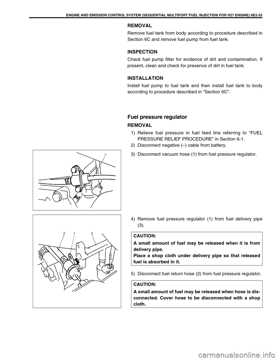
Fuel pressure regulator
REMOVAL
1) Relieve fuel pressure in fuel feed line referring to “FUEL
PRESSURE RELIEF PROCEDURE” in Section 6-1.
2) Disconnect negative (–) cable from battery.
3) Disconnect vacuum hose (1) from fuel pressure regulator.
4) Remove fuel pressure regulator (1) from fuel delivery pipe
(3).
5) Disconnect fuel return hose (2) from fuel pressure regulator.
CAUTION:
A small amount of fuel may be released when it is from
delivery pipe.
Place a shop cloth under delivery pipe so that released
fuel is absorbed in it.
CAUTION:
A small amount of fuel may be released when hose is dis-
connected. Cover hose to be disconnected with a shop
cloth.
Page 379 of 656

6E2-46 ENGINE AND EMISSION CONTROL SYSTEM (SEQUENTIAL MULTIPORT FUEL INJECTION FOR H27 ENGINE)
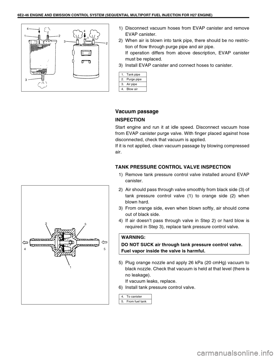
1) Disconnect vacuum hoses from EVAP canister and remove
EVAP canister.
2) When air is blown into tank pipe, there should be no restric-
tion of flow through purge pipe and air pipe.
If operation differs from above description, EVAP canister
must be replaced.
3) Install EVAP canister and connect hoses to canister.
Vacuum passage
INSPECTION
Start engine and run it at idle speed. Disconnect vacuum hose
from EVAP canister purge valve. With finger placed against hose
disconnected, check that vacuum is applied.
If it is not applied, clean vacuum passage by blowing compressed
air.
TANK PRESSURE CONTROL VALVE INSPECTION
1) Remove tank pressure control valve installed around EVAP
canister.
2) Air should pass through valve smoothly from black side (3) of
tank pressure control valve (1) to orange side (2) when
blown hard.
3) From orange side, even when blown softly, air should come
out of black side.
4) If air doesn’t pass through valve in Step 2) or hard blow is
required in Step 3), replace tank pressure control valve.
5) Plug orange nozzle and apply 26 kPa (20 cmHg) vacuum to
black nozzle. Check that vacuum is held at that level (there is
no leakage).
If vacuum leaks, replace.
6) Install tank pressure control valve.
1. Tank pipe
2. Purge pipe
3. Air pipe
4. Blow air
WARNING:
DO NOT SUCK air through tank pressure control valve.
Fuel vapor inside the valve is harmful.
4. To canister
5. From fuel tank
Page 418 of 656

AUTOMATIC TRANSMISSION (4 A/T) 7B1-9
Precaution in Diagnosing Trouble
•Don’t disconnect couplers from PCM (ECM), battery cable
from battery, PCM ground wire harness from engine or main
fuse before checking the diagnosis information (DTC, freeze
frame data, etc.) stored in PCM memory. Such disconnec-
tion will clear memorized information in PCM memory.
•Using SUZUKI scan tool or also generic scan tool for vehicle
without monitor connector, the diagnostic information stored
in PCM memory can be checked and cleared as well. Before
its use, be sure to read Operator’s (Instruction) Manual sup-
plied with it carefully to have good understanding of its func-
tions and usage.
•Priorities for diagnosing troubles
If two or more diagnostic trouble codes (DTCs) are stored,
proceed to the flow table of the DTC which was detected
earliest in the order and follow the instruction in that table.
If no instructions are given, troubleshoot diagnostic trouble
codes according to the following priorities.
–Diagnostic trouble codes (DTCs) other than DTC P0171/
P0172/P0174/P0175 (Fuel system too lean/too rich), DTC
P0300/P0301/P0302/P0303/P0304/P0305/P0306 (Misfire
detected) and DTC P0400 (EGR flow malfunction)
–DTC P0171/P0172/P0174/P0175 (Fuel system too lean/too
rich) and DTC P0400 (EGR flow malfunction)
–DTC P0300/P0301/P0302/P0303/P0304/P0305/P0306
(Misfire detected)
•Be sure to read “PRECAUTIONS FOR ELECTRICAL CIR-
CUIT SERVICE” in Section 0A before inspection and
observe what is written there.
•PCM replacement
When substituting a known-good PCM, check for following
conditions.
Neglecting this check may result in damage to a good PCM.
–All relays and actuators have resistance of specified value.
–MAF sensor, MDP sensor, TP sensor and fuel tank pres-
sure sensor are in good condition. Also, the power circuit of
these sensors is not shorted to the ground.
Page 548 of 656

BODY SERVICE 9-3
Body Structure
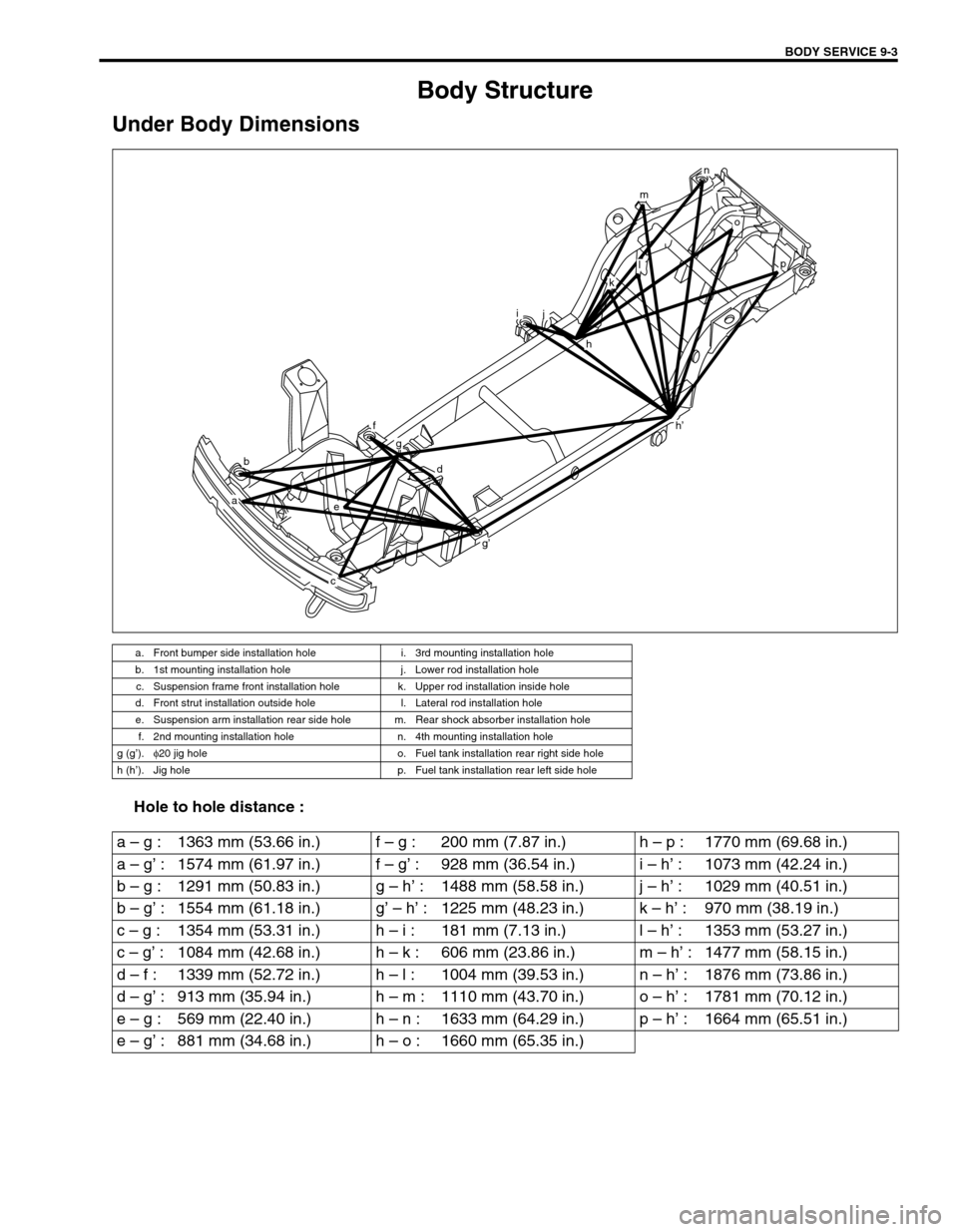
Under Body Dimensions
Hole to hole distance :
a. Front bumper side installation hole i. 3rd mounting installation hole
b. 1st mounting installation hole j. Lower rod installation hole
c. Suspension frame front installation hole k. Upper rod installation inside hole
d. Front strut installation outside hole l. Lateral rod installation hole
e. Suspension arm installation rear side hole m. Rear shock absorber installation hole
f. 2nd mounting installation hole n. 4th mounting installation hole
g (g’).φ
20 jig hole o. Fuel tank installation rear right side hole
h (h’). Jig hole p. Fuel tank installation rear left side hole
b
a
h’
e
f
g
d
g’
c
ij
h
o
p
n
m
l
k
a – g : 1363 mm (53.66 in.) f – g : 200 mm (7.87 in.) h – p : 1770 mm (69.68 in.)
a – g’ : 1574 mm (61.97 in.) f – g’ : 928 mm (36.54 in.) i – h’ : 1073 mm (42.24 in.)
b – g : 1291 mm (50.83 in.) g – h’ : 1488 mm (58.58 in.) j – h’ : 1029 mm (40.51 in.)
b – g’ : 1554 mm (61.18 in.) g’ – h’ : 1225 mm (48.23 in.) k – h’ : 970 mm (38.19 in.)
c – g : 1354 mm (53.31 in.) h – i : 181 mm (7.13 in.) l – h’ : 1353 mm (53.27 in.)
c – g’ : 1084 mm (42.68 in.) h – k : 606 mm (23.86 in.) m – h’ : 1477 mm (58.15 in.)
d – f : 1339 mm (52.72 in.) h – l : 1004 mm (39.53 in.) n – h’ : 1876 mm (73.86 in.)
d – g’ : 913 mm (35.94 in.) h – m : 1110 mm (43.70 in.) o – h’ : 1781 mm (70.12 in.)
e – g : 569 mm (22.40 in.) h – n : 1633 mm (64.29 in.) p – h’ : 1664 mm (65.51 in.)
e – g’ : 881 mm (34.68 in.) h – o : 1660 mm (65.35 in.)