Page 27 of 656

1B-2 AIR CONDITIONING (OPTIONAL)
Charging .................................................... 1B-22
On-Vehicle Service ...................................... 1B-25
Precaution .................................................. 1B-25
Piping ..................................................... 1B-25
Handling refrigerant HFC-134a (R-134a) 1B-26
Refrigerant recovery............................... 1B-26
Refrigerant charge ................................. 1B-26
Replenishing compressor oil .................. 1B-27
Rear A/C Unit (Rear A/C Evaporator) ........ 1B-28
Rear Expansion Valve ............................... 1B-29
Rear A/C Evaporator Temperature
Controller ................................................... 1B-30
Refrigerant Pipes and Hoses ..................... 1B-31
Solenoid Valve ........................................... 1B-32
Rear Blower Motor Assembly .................... 1B-33Rear Blower Motor Relay and Solenoid
Valve Relay................................................ 1B-34
Rear A/C Main Switch................................ 1B-34
Rear Blower Motor Resistor....................... 1B-35
Rear Blower Motor Switch ......................... 1B-36
Rear A/C No.1 and No.2 Duct ................... 1B-37
Rear A/C No.1 duct ................................ 1B-37
Rear A/C No.2 duct ................................ 1B-37
Compressor Assembly............................... 1B-38
Magnet Clutch............................................ 1B-41
Required Service Materials ......................... 1B-44
Tightening Torque Specification................ 1B-44
Special Tools ............................................... 1B-44
Page 69 of 656
1B-44 AIR CONDITIONING (OPTIONAL)
Required Service Materials
Tightening Torque Specification
Special Tools
MaterialRecommended SUZUKI product
(Part Number)Use
Compressor oil (refrigerant oil) COMPRESSOR OIL (ND-OIL8, 250 cc)
(99000-27080)O-ring
Each component
Fastening partTightening torque
Nm kg-m lb-ft
Refrigerant pipe (8 mm (0.31 in.)) 13 1.3 9.5
Refrigerant pipe (12.7 mm (0.5 in.)) 22 2.2 16.0
Refrigerant pipe (16 mm (0.63 in.)) 33 3.3 24.0
Armature plate nut 18 1.8 13.0
09900-06107 09920-53740 09990-06010
Snap ring pliers
(Opening type)Armature plate holder Manifold gauge set
See NOTE below.
09990-86011 09991-06010
Gas leak detector Magnet clutch pulley
installer
NOTE:
This kit includes the following items.
1. Manifold gauge, 2. Changing hose, 3. Quick connector, 4. Refrigerant container tap valve,
5. Refrigerant container T joint, 6. Packing set
Page 187 of 656

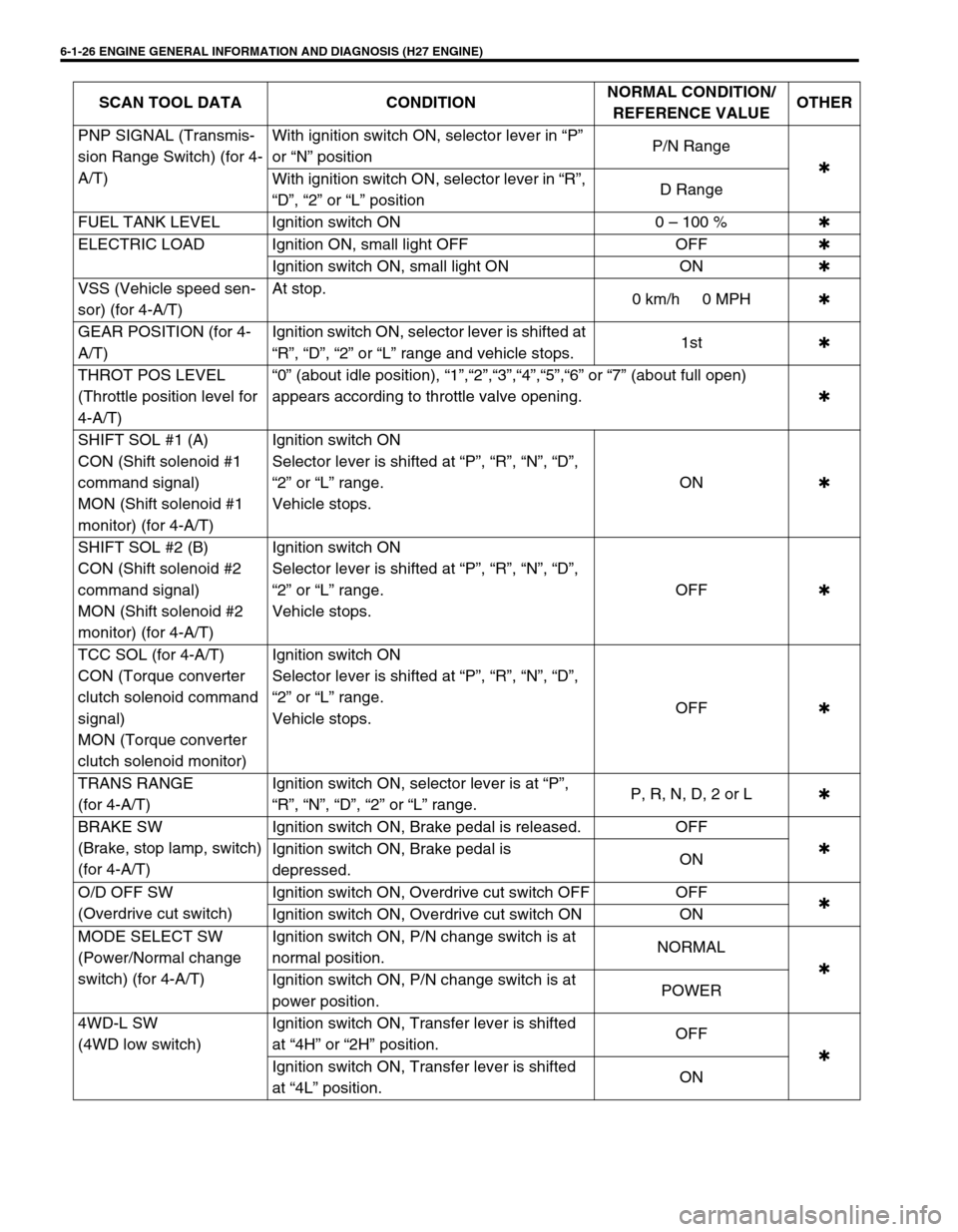
6-1-26 ENGINE GENERAL INFORMATION AND DIAGNOSIS (H27 ENGINE)
PNP SIGNAL (Transmis-
sion Range Switch) (for 4-
A/T)With ignition switch ON, selector lever in “P”
or “N” positionP/N Range
✱
With ignition switch ON, selector lever in “R”,
“D”, “2” or “L” positionD Range
FUEL TANK LEVEL Ignition switch ON 0 – 100 %✱
ELECTRIC LOAD Ignition ON, small light OFF OFF✱
Ignition switch ON, small light ON ON✱
VSS (Vehicle speed sen-
sor) (for 4-A/T)At stop.
0 km/h 0 MPH✱
GEAR POSITION (for 4-
A/T)Ignition switch ON, selector lever is shifted at
“R”, “D”, “2” or “L” range and vehicle stops.1st✱
THROT POS LEVEL
(Throttle position level for
4-A/T)“0” (about idle position), “1”,“2”,“3”,“4”,“5”,“6” or “7” (about full open)
appears according to throttle valve opening.✱
SHIFT SOL #1 (A)
CON (Shift solenoid #1
command signal)
MON (Shift solenoid #1
monitor) (for 4-A/T)Ignition switch ON
Selector lever is shifted at “P”, “R”, “N”, “D”,
“2” or “L” range.
Vehicle stops.ON✱
SHIFT SOL #2 (B)
CON (Shift solenoid #2
command signal)
MON (Shift solenoid #2
monitor) (for 4-A/T)Ignition switch ON
Selector lever is shifted at “P”, “R”, “N”, “D”,
“2” or “L” range.
Vehicle stops.OFF✱
TCC SOL (for 4-A/T)
CON (Torque converter
clutch solenoid command
signal)
MON (Torque converter
clutch solenoid monitor)Ignition switch ON
Selector lever is shifted at “P”, “R”, “N”, “D”,
“2” or “L” range.
Vehicle stops.OFF✱
TRANS RANGE
(for 4-A/T)Ignition switch ON, selector lever is at “P”,
“R”, “N”, “D”, “2” or “L” range.P, R, N, D, 2 or L✱
BRAKE SW
(Brake, stop lamp, switch)
(for 4-A/T)Ignition switch ON, Brake pedal is released. OFF
✱
Ignition switch ON, Brake pedal is
depressed.ON
O/D OFF SW
(Overdrive cut switch)Ignition switch ON, Overdrive cut switch OFF OFF
✱
Ignition switch ON, Overdrive cut switch ON ON
MODE SELECT SW
(Power/Normal change
switch) (for 4-A/T)Ignition switch ON, P/N change switch is at
normal position.NORMAL
✱
Ignition switch ON, P/N change switch is at
power position.POWER
4WD-L SW
(4WD low switch)Ignition switch ON, Transfer lever is shifted
at “4H” or “2H” position.OFF
✱
Ignition switch ON, Transfer lever is shifted
at “4L” position.ON SCAN TOOL DATA CONDITIONNORMAL CONDITION/
REFERENCE VALUEOTHER
Page 293 of 656
6A2-6 ENGINE MECHANICAL (H27 ENGINE)
INSTALLATION
1) Install new intake manifold gaskets (1) to cylinder heads.
2) Install intake manifold (1).
Tighten bolts and nuts to specified torque.
Tightening torque
Intake manifold bolt and nut (a) :
23 N·m (2.3 kg-m, 16.5 lb-ft)
3) Install throttle body (2) to intake collector (1) with new throttle
body gasket.
Tighten bolts and nuts to specified torque.
Tightening torque
Throttle body bolt and nut (b) :
23 N·m (2.3 kg-m, 16.5 lb-ft)
4) Install EGR valve (1), EVAP canister purge valve (2), mani-
fold absolute pressure (MAP) sensor and each hoses to
intake collector and throttle body if removed.
Use new gasket, when installing IAC valve and EGR valve.
5) Install throttle body and intake collector assembly to intake
manifold with new intake collector gaskets.
1
(a)
(a)(a)
(a)
2 1
(b)
(b)
3. EVAP canister purge valve hose
2
1
3
Page 301 of 656
6A2-14 ENGINE MECHANICAL (H27 ENGINE)
Camshaft and Valve Lash Adjuster
1. RH bank 2nd timing chain 6. LH bank intake camshaft 11. Timing chain guide No.5
2. RH bank exhaust camshaft 7. LH bank exhaust camshaft 12. Valve lash adjuster
3. RH bank intake camshaft 8. LH bank intake camshaft holder 13. Camshaft housing bolt
4. RH bank exhaust camshaft holder 9. LH bank exhaust camshaft holder Tightening Torque
5. RH bank intake camshaft holder 10. LH bank camshaft holder Apply engine oil to sliding surface
of each parts.
Page 302 of 656

ENGINE MECHANICAL (H27 ENGINE) 6A2-15
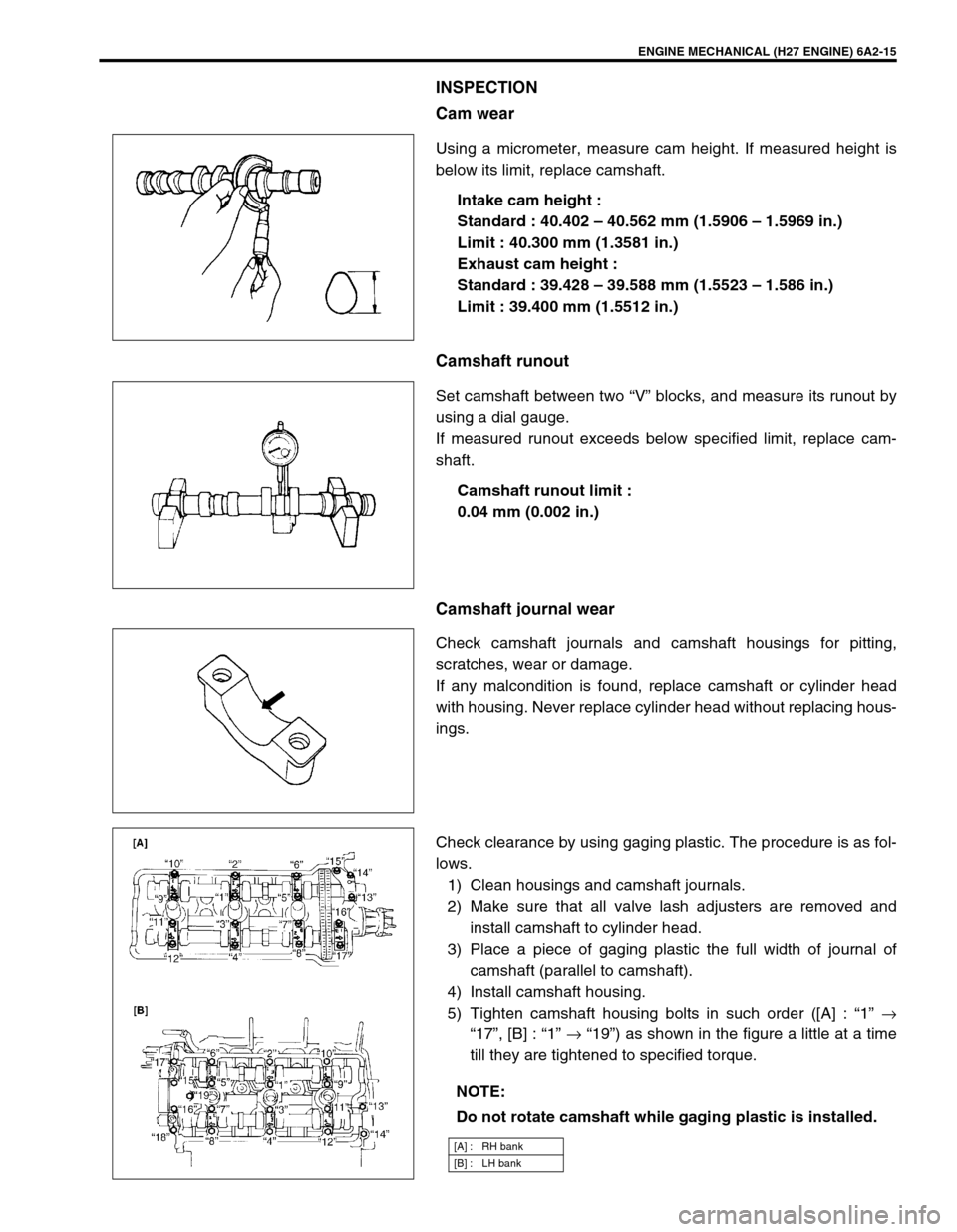
INSPECTION
Cam wear
Using a micrometer, measure cam height. If measured height is
below its limit, replace camshaft.
Intake cam height :
Standard : 40.402 – 40.562 mm (1.5906 – 1.5969 in.)
Limit : 40.300 mm (1.3581 in.)
Exhaust cam height :
Standard : 39.428 – 39.588 mm (1.5523 – 1.586 in.)
Limit : 39.400 mm (1.5512 in.)
Camshaft runout
Set camshaft between two “V” blocks, and measure its runout by
using a dial gauge.
If measured runout exceeds below specified limit, replace cam-
shaft.
Camshaft runout limit :
0.04 mm (0.002 in.)
Camshaft journal wear
Check camshaft journals and camshaft housings for pitting,
scratches, wear or damage.
If any malcondition is found, replace camshaft or cylinder head
with housing. Never replace cylinder head without replacing hous-
ings.
Check clearance by using gaging plastic. The procedure is as fol-
lows.
1) Clean housings and camshaft journals.
2) Make sure that all valve lash adjusters are removed and
install camshaft to cylinder head.
3) Place a piece of gaging plastic the full width of journal of
camshaft (parallel to camshaft).
4) Install camshaft housing.
5) Tighten camshaft housing bolts in such order ([A] : “1” →
“17”, [B] : “1” → “19”) as shown in the figure a little at a time
till they are tightened to specified torque.
NOTE:
Do not rotate camshaft while gaging plastic is installed.
[A] : RH bank
[B] : LH bank
Page 304 of 656
ENGINE MECHANICAL (H27 ENGINE) 6A2-17
Valves and Cylinder Heads
1. Cylinder block 6. Exhaust valve 11. Valve stem oil seal 16. Cylinder head bolt
(hex hole bolt)
2. RH bank cylinder head 7. Intake valve 12. Valve spring retainer Tightening Torque
3. LH bank cylinder head 8. Valve spring seat 13. Valve cotter Do not reuse
4. RH bank cylinder head gasket :
Carved lot number on cylinder head
gasket should face up (toward cylinder
head side).9. Outer valve spring :
Be sure to position spring in place with
its bottom end (small-pitch end) facing
the bottom (valve spring seat side).14. Valve guide Apply engine oil to
sliding surface of
each parts.
5. LH bank cylinder head gasket :
Carved lot number on cylinder head
gasket should face up (toward cylinder
head side).10. Inner valve spring :
Be sure to position spring in place with
its bottom end (small-pitch end) facing
the bottom (valve spring seat side).15. Cylinder head bolt
Page 306 of 656

ENGINE MECHANICAL (H27 ENGINE) 6A2-19
5) Install cylinder head to block.
After applying oil to cylinder head bolts, tighten them gradu-
ally as follows.
a) Tighten all bolts to 53 N·m (5.3 kg-m, 38.5 lb-ft) according
to numerical order in the figure.
b) In the same manner as in a), tighten them to 84 N·m (8.4
kg-m, 61.0 lb-ft).
c) Loosen all bolts until tightening torque is reduced to 0 in
reverse order of tightening.
d) In the same manner as in a), tighten them to 53 N·m (5.3
kg-m, 38.5 lb-ft).
e) In the same manner as in a) again, tighten them to speci-
fied torque.
Tightening torque
Cylinder head bolt (a) : 105 N·m (10.5 kg-m, 76.0 lb-ft)
Cylinder head bolt (hex hole bolt) (b) :
11 N·m (1.1 kg-m, 7.5 lb-ft)
6) Install water outlet cap.
7) Check timing mark on crankshaft as shown in the figure.
8) Install valve lash adjuster, camshaft, CMP sensor and RH
bank 2nd timing chain.
Refer to “CAMSHAFT AND VALVE LASH ADJUSTER” and
“RH (NO.2) BANK 2ND TIMING CHAIN AND CHAIN TEN-
SIONER” in this section. For CMP sensor, refer to “CMP
SENSOR” in Section 6F2.
9) Install 1st timing chain.
Refer to “1ST TIMING CHAIN AND CHAIN TENSIONER” in
this section.
10) Install LH bank 2nd timing chain.
Refer to “LH (NO.1) BANK 2ND TIMING CHAIN AND CHAIN
TENSIONER” in this section.
11) Install timing chain cover.
Refer to “TIMING CHAIN COVER” in this section. NOTE:
Don’t forget to install (b) bolts as shown in the figure.
1. Hex hole bolt
2. Crankshaft pulley side
3. Flywheel side
[A] RH bank
[B] LH bank
1. Crank timing pulley key
2. Oil jet