Page 463 of 656

7B1-54 AUTOMATIC TRANSMISSION (4 A/T)
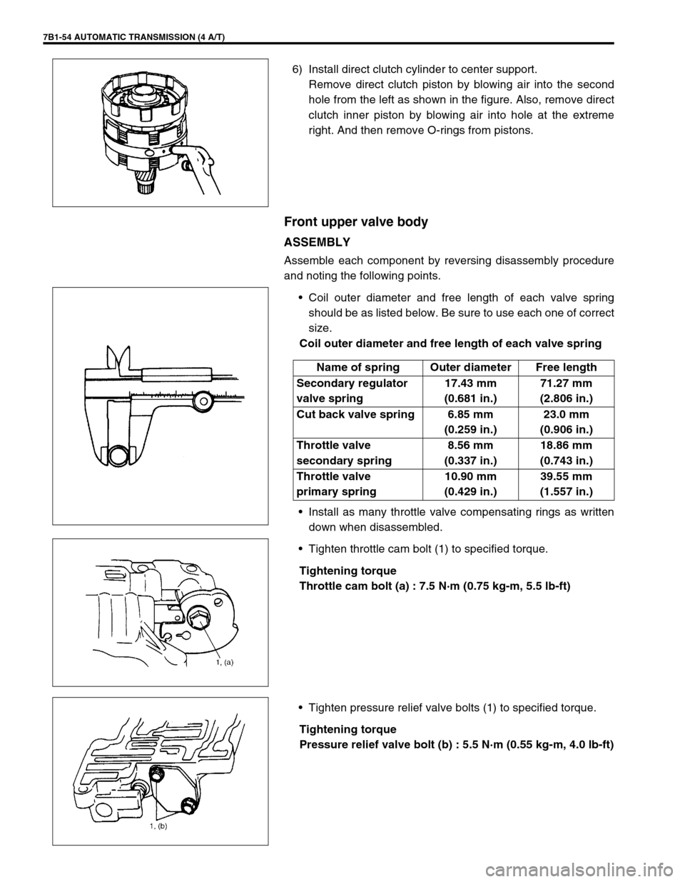
6) Install direct clutch cylinder to center support.
Remove direct clutch piston by blowing air into the second
hole from the left as shown in the figure. Also, remove direct
clutch inner piston by blowing air into hole at the extreme
right. And then remove O-rings from pistons.
Front upper valve body
ASSEMBLY
Assemble each component by reversing disassembly procedure
and noting the following points.
•Coil outer diameter and free length of each valve spring
should be as listed below. Be sure to use each one of correct
size.
Coil outer diameter and free length of each valve spring
•Install as many throttle valve compensating rings as written
down when disassembled.
•Tighten throttle cam bolt (1) to specified torque.
Tightening torque
Throttle cam bolt (a) : 7.5 N·m (0.75 kg-m, 5.5 lb-ft)
•Tighten pressure relief valve bolts (1) to specified torque.
Tightening torque
Pressure relief valve bolt (b) : 5.5 N·m (0.55 kg-m, 4.0 lb-ft)
Name of spring Outer diameter Free length
Secondary regulator
valve spring17.43 mm
(0.681 in.)71.27 mm
(2.806 in.)
Cut back valve spring 6.85 mm
(0.259 in.)23.0 mm
(0.906 in.)
Throttle valve
secondary spring8.56 mm
(0.337 in.)18.86 mm
(0.743 in.)
Throttle valve
primary spring10.90 mm
(0.429 in.)39.55 mm
(1.557 in.)
Page 467 of 656

7B1-58 AUTOMATIC TRANSMISSION (4 A/T)
ASSEMBLY
Assemble each component by reversing disassembly procedure
and noting the following points.
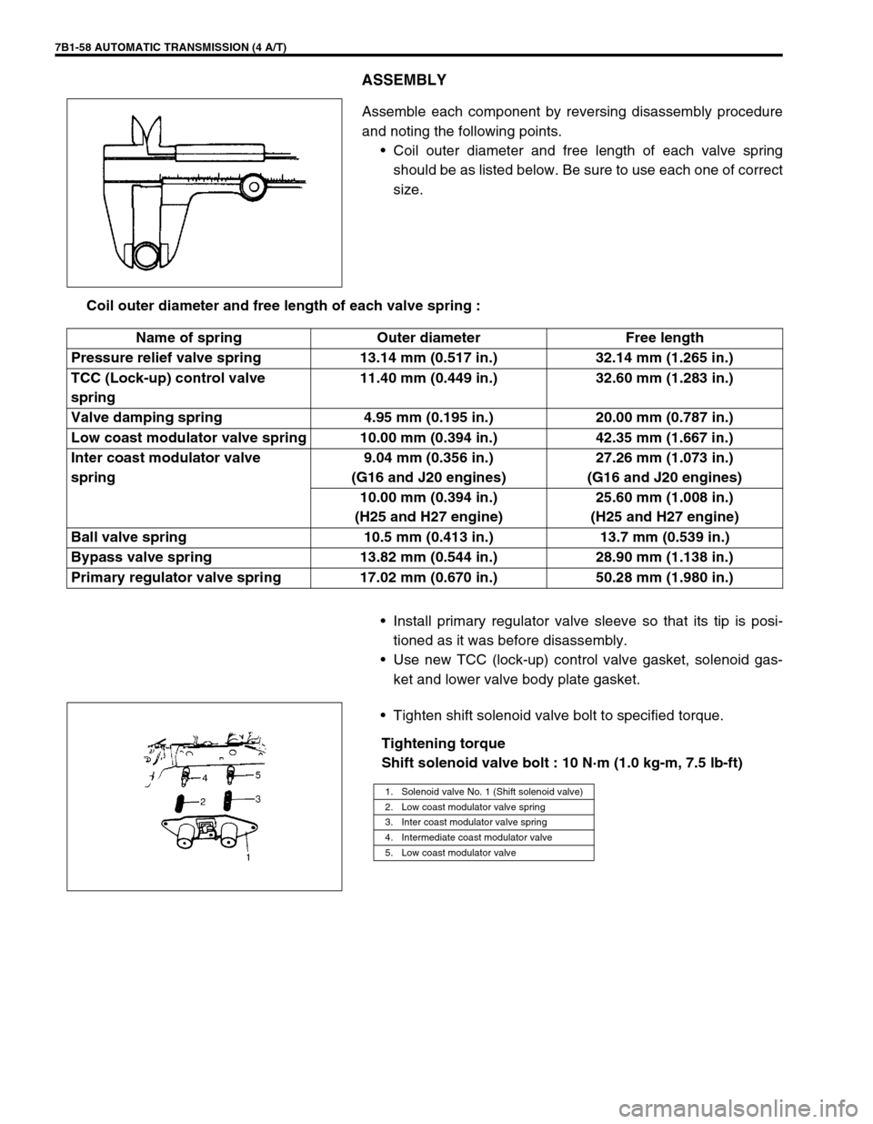
•Coil outer diameter and free length of each valve spring
should be as listed below. Be sure to use each one of correct
size.
Coil outer diameter and free length of each valve spring :
•Install primary regulator valve sleeve so that its tip is posi-
tioned as it was before disassembly.
•Use new TCC (lock-up) control valve gasket, solenoid gas-
ket and lower valve body plate gasket.
•Tighten shift solenoid valve bolt to specified torque.
Tightening torque
Shift solenoid valve bolt : 10 N·m (1.0 kg-m, 7.5 lb-ft)
Name of spring Outer diameter Free length
Pressure relief valve spring 13.14 mm (0.517 in.) 32.14 mm (1.265 in.)
TCC (Lock-up) control valve
spring11.40 mm (0.449 in.) 32.60 mm (1.283 in.)
Valve damping spring 4.95 mm (0.195 in.) 20.00 mm (0.787 in.)
Low coast modulator valve spring 10.00 mm (0.394 in.) 42.35 mm (1.667 in.)
Inter coast modulator valve
spring9.04 mm (0.356 in.)
(G16 and J20 engines)27.26 mm (1.073 in.)
(G16 and J20 engines)
10.00 mm (0.394 in.)
(H25 and H27 engine)25.60 mm (1.008 in.)
(H25 and H27 engine)
Ball valve spring 10.5 mm (0.413 in.) 13.7 mm (0.539 in.)
Bypass valve spring 13.82 mm (0.544 in.) 28.90 mm (1.138 in.)
Primary regulator valve spring 17.02 mm (0.670 in.) 50.28 mm (1.980 in.)
1. Solenoid valve No. 1 (Shift solenoid valve)
2. Low coast modulator valve spring
3. Inter coast modulator valve spring
4. Intermediate coast modulator valve
5. Low coast modulator valve
Page 468 of 656
AUTOMATIC TRANSMISSION (4 A/T) 7B1-59
•Tighten TCC (lock-up) solenoid valve bolt to specified
torque.
Tightening torque
TCC solenoid valve bolt :
5.5 N·m (0.55 kg-m, 4.0 lb-ft)
•Tighten pressure relief valve bolt to specified torque.
Tightening torque
Pressure relief valve bolt :
5.5 N·m (0.55 kg-m, 4.0 lb-ft)
•Tighten lower valve body plate (1), TCC (lock-up) control
valve plate (2) flange bolt to specified torque.
Tightening torque
Lower valve body and TCC control valve Plate bolts :
5.5 N·m (0.55 kg-m, 4.0 lb-ft)
Unit Assembly
1) Apply A/T fluid to new O-ring and spring and install them to
accumulator piston and install accumulator piston to trans-
mission case.
1. Solenoid valve No. 2 (TCC solenoid valve)
2. O-ring
4. Upper spring
Page:
< prev 1-8 9-16 17-24