1999 SUZUKI GRAND VITARA torque valve
[x] Cancel search: torque valvePage 331 of 656
6C-4 ENGINE FUEL
INSTALLATION
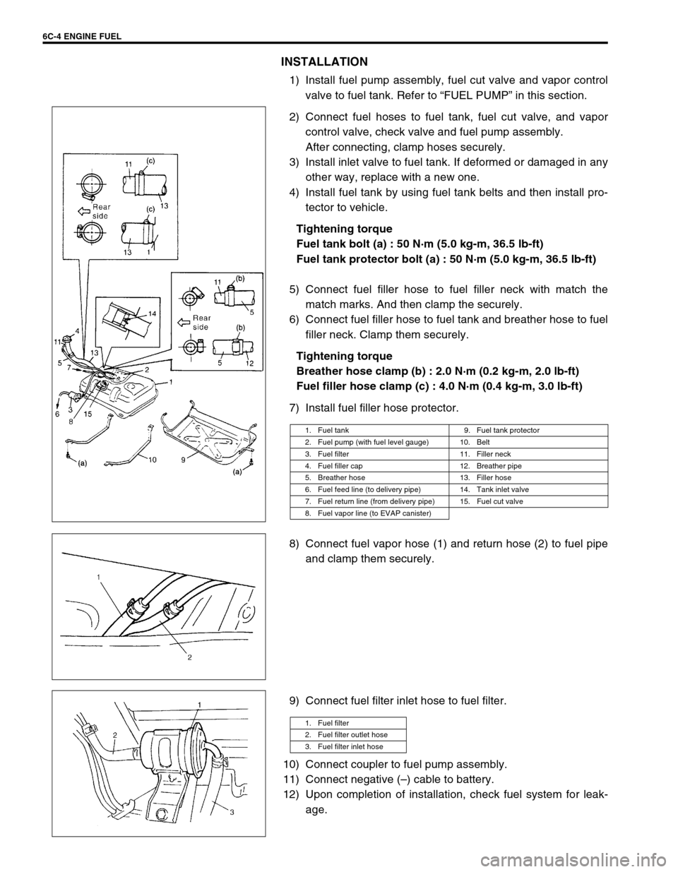
1) Install fuel pump assembly, fuel cut valve and vapor control
valve to fuel tank. Refer to “FUEL PUMP” in this section.
2) Connect fuel hoses to fuel tank, fuel cut valve, and vapor
control valve, check valve and fuel pump assembly.
After connecting, clamp hoses securely.
3) Install inlet valve to fuel tank. If deformed or damaged in any
other way, replace with a new one.
4) Install fuel tank by using fuel tank belts and then install pro-
tector to vehicle.
Tightening torque
Fuel tank bolt (a) : 50 N·m (5.0 kg-m, 36.5 lb-ft)
Fuel tank protector bolt (a) : 50 N·m (5.0 kg-m, 36.5 lb-ft)
5) Connect fuel filler hose to fuel filler neck with match the
match marks. And then clamp the securely.
6) Connect fuel filler hose to fuel tank and breather hose to fuel
filler neck. Clamp them securely.
Tightening torque
Breather hose clamp (b) : 2.0 N·m (0.2 kg-m, 2.0 lb-ft)
Fuel filler hose clamp (c) : 4.0 N·m (0.4 kg-m, 3.0 lb-ft)
7) Install fuel filler hose protector.
8) Connect fuel vapor hose (1) and return hose (2) to fuel pipe
and clamp them securely.
9) Connect fuel filter inlet hose to fuel filter.
10) Connect coupler to fuel pump assembly.
11) Connect negative (–) cable to battery.
12) Upon completion of installation, check fuel system for leak-
age.
1. Fuel tank 9. Fuel tank protector
2. Fuel pump (with fuel level gauge) 10. Belt
3. Fuel filter 11. Filler neck
4. Fuel filler cap 12. Breather pipe
5. Breather hose 13. Filler hose
6. Fuel feed line (to delivery pipe) 14. Tank inlet valve
7. Fuel return line (from delivery pipe) 15. Fuel cut valve
8. Fuel vapor line (to EVAP canister)
1. Fuel filter
2. Fuel filter outlet hose
3. Fuel filter inlet hose
Page 335 of 656

6E2-2 ENGINE AND EMISSION CONTROL SYSTEM (SEQUENTIAL MULTIPORT FUEL INJECTION FOR H27 ENGINE)
Fuel injector.......................................... 6E2-26
Electronic Control System........................ 6E2-31
Engine control module (ECM)/
powertrain control module (PCM) ........ 6E2-31
Mass air flow sensor (MAF sensor)...... 6E2-32
Intake air temperature (IAT) sensor ..... 6E2-34
Throttle position sensor (TP sensor) .... 6E2-35
Engine coolant temperature sensor
(ECT sensor) ........................................ 6E2-36
Heated oxygen sensor (sensor 1) ........ 6E2-37
Heated oxygen sensor (sensor 2) ........ 6E2-38
Vehicle speed sensor (VSS) ................ 6E2-39
Manifold absolute pressure sensor ...... 6E2-39
Fuel level sensor (sender gauge)......... 6E2-41
Crankshaft position sensor................... 6E2-41Main relay ............................................ 6E2-41
Fuel pump relay ................................... 6E2-42
Fuel cut operation ................................ 6E2-43
Emission Control System......................... 6E2-44
EGR system (if equipped) .................... 6E2-44
EVAP canister ...................................... 6E2-45
Vacuum passage ................................. 6E2-46
PCV System ............................................ 6E2-47
PCV hose ............................................. 6E2-47
PCV valve ............................................ 6E2-47
PCV system ......................................... 6E2-48
Tightening Torque Specification.............. 6E2-48
Special Tool ............................................... 6E2-48
General Description
The engine and emission control system has 4 major sub-systems: air intake system, fuel delivery system, elec-
tronic control system and emission control system.
Air intake system includes air cleaner, mass air flow sensor, throttle body, idle air control valve and intake man-
ifold.
Fuel delivery system includes fuel pump, delivery pipe, fuel pressure regulator, fuel injectors, etc.
Electronic control system includes ECM (PCM), various sensors and controlled devices.
Emission control system includes EGR, EVAP and PCV systems.
Page 355 of 656
6E2-22 ENGINE AND EMISSION CONTROL SYSTEM (SEQUENTIAL MULTIPORT FUEL INJECTION FOR H27 ENGINE)
3) Remove air cleaner outlet hose and remove IAC valve from
throttle body.
4) Connect connector to IAC valve.
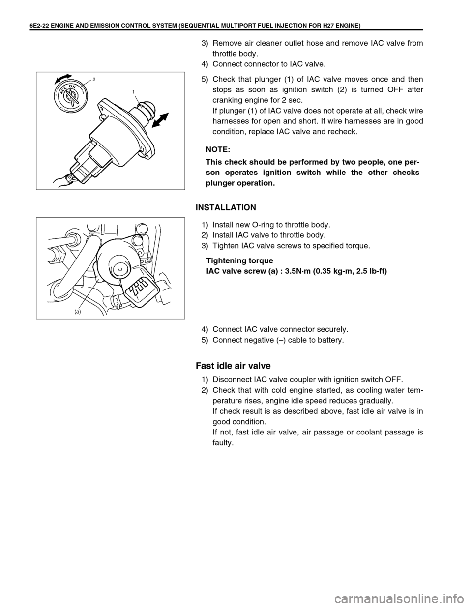
5) Check that plunger (1) of IAC valve moves once and then
stops as soon as ignition switch (2) is turned OFF after
cranking engine for 2 sec.
If plunger (1) of IAC valve does not operate at all, check wire
harnesses for open and short. If wire harnesses are in good
condition, replace IAC valve and recheck.
INSTALLATION
1) Install new O-ring to throttle body.
2) Install IAC valve to throttle body.
3) Tighten IAC valve screws to specified torque.
Tightening torque
IAC valve screw (a) : 3.5N·m (0.35 kg-m, 2.5 lb-ft)
4) Connect IAC valve connector securely.
5) Connect negative (–) cable to battery.
Fast idle air valve
1) Disconnect IAC valve coupler with ignition switch OFF.
2) Check that with cold engine started, as cooling water tem-
perature rises, engine idle speed reduces gradually.
If check result is as described above, fast idle air valve is in
good condition.
If not, fast idle air valve, air passage or coolant passage is
faulty. NOTE:
This check should be performed by two people, one per-
son operates ignition switch while the other checks
plunger operation.
Page 368 of 656

ENGINE AND EMISSION CONTROL SYSTEM (SEQUENTIAL MULTIPORT FUEL INJECTION FOR H27 ENGINE) 6E2-35
Throttle position sensor (TP sensor)
INSPECTION
1) Disconnect negative (–) cable at battery and coupler from TP
sensor (4).
2) Using ohmmeter, check resistance between terminals under
each condition given in table below.
If check result is not satisfactory, replace TP sensor.
TP sensor specification:
3) Connect TP sensor coupler securely.
4) Connect negative cable to battery.
REMOVAL
1) Disconnect negative (–) cable at battery.
2) Disconnect coupler from TP sensor.
3) Remove TP sensor from throttle body.
INSTALLATION
1) Install TP sensor (1) to throttle body (2).
Fit TP sensor (1) to throttle body (2) in such way that its
holes are a little away from TP sensor screw holes as shown
in the figure and turn TP sensor (1) clockwise so that those
holes align.
Tightening torque
TP sensor screw
(a) : 3.5 N·m (0.35 kg-m, 2.5 lb-ft)
2) Connect coupler to TP sensor securely.
3) Connect battery negative (–) cable to battery. TERMINALS RESISTANCE
Between 1 and
3 terminals4.0 – 6.0 kΩ
ΩΩ Ω
Between 1 and
2 terminals0.02 – 6.0 kΩ
ΩΩ Ω
varying linearly according to
throttle valve opening
1. Ground terminal
2. Output voltage terminal
3. Reference voltage terminal
Page 381 of 656

6E2-48 ENGINE AND EMISSION CONTROL SYSTEM (SEQUENTIAL MULTIPORT FUEL INJECTION FOR H27 ENGINE)
PCV system
PCV HOSE
Check hoses for connection, leakage, clog, and deterioration.
Replace as necessary.
Tightening Torque Specification
Special Tool
NOTE:
Be sure to check that there is no obstruction in PCV
valve or its hoses (6) before checking engine idle speed/
IAC duty for obstructed PCV valve or hose hampers its
accurate checking.
1. EVAP canister purge valve 4. EGR pipe
2. EVAP canister purge valve hose 5. EGR valve
3. Breather hose 6. PCV hose
Fastening partTightening torque
Nm kg-m lb-ft
Heated oxygen sensor 45 4.5 32.5
Fuel pressure regulator bolts 10 1.0 7.5
Fuel pipe union bolts 30 3.0 22.0
Engine coolant temp. sensor 15 1.5 11.0
09912-58441 09912-58431 09912-58490 09912-58421
Pressure gauge Pressure hose 3-way joint & hose Checking tool set
(See NOTE “A”.)
Page 411 of 656
7B1-2 AUTOMATIC TRANSMISSION (4 A/T)
Stall Test ................................................... 7B1-38
Line Pressure Test .................................... 7B1-39
Road Test ................................................. 7B1-40
Manual Road Test..................................... 7B1-41
Time Lag Test ........................................... 7B1-41
Engine Brake Test .................................... 7B1-42
“P” Range Test.......................................... 7B1-42
On-Vehicle Service ..................................... 7B1-43
Maintenance Service ................................ 7B1-43
Fluid level .............................................. 7B1-43
Fluid change.......................................... 7B1-44
A/T Throttle Cable ..................................... 7B1-45Solenoid Valves (Shift Solenoid Valves
and TCC Solenoid Valve) ......................... 7B1-45
MANUAL SELECTOR ASSEMBLY .......... 7B1-46
SELECT CABLE ....................................... 7B1-48
Unit Repair .................................................. 7B1-49
Sub-Assembly Repair ............................... 7B1-49
Overdrive (case side) ............................ 7B1-49
Forward clutch ...................................... 7B1-50
Front upper valve body ......................... 7B1-54
Unit Assembly ........................................... 7B1-59
Tightening Torque Specification............... 7B1-60
Special Tool ................................................ 7B1-61
Page 425 of 656
7B1-16 AUTOMATIC TRANSMISSION (4 A/T)
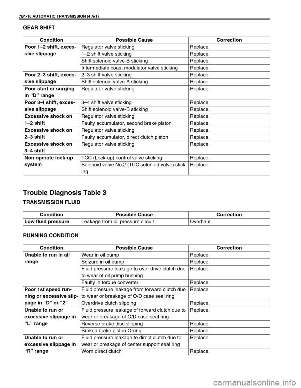
GEAR SHIFT
Trouble Diagnosis Table 3
TRANSMISSION FLUID
RUNNING CONDITION
Condition Possible Cause Correction
Poor 1–2 shift, exces-
sive slippageRegulator valve sticking Replace.
1–2 shift valve sticking Replace.
Shift solenoid valve-B sticking Replace.
Intermediate coast modulator valve sticking Replace.
Poor 2–3 shift, exces-
sive slippage2–3 shift valve sticking Replace.
Shift solenoid valve-A sticking Replace.
Poor start or surging
in “D” rangeRegulator valve sticking Replace.
Poor 3-4 shift, exces-
sive slippage3–4 shift valve sticking Replace.
Shift solenoid valve-B sticking Replace.
Excessive shock on
1–2 shiftRegulator valve sticking Replace.
Faulty accumulator, second brake piston Replace.
Excessive shock on
2–3 shiftRegulator valve sticking Replace.
Faulty accumulator, direct clutch piston Replace.
Excessive shock on
3–4 shiftRegulator valve sticking Replace.
Non operate lock-up
systemTCC (Lock-up) control valve sticking Replace.
Solenoid valve No.2 (TCC solenoid valve) stick-
ingReplace.
Condition Possible Cause Correction
Low fluid pressureLeakage from oil pressure circuit Overhaul.
Condition Possible Cause Correction
Unable to run in all
rangeWear in oil pump Replace.
Seizure in oil pump Replace.
Fluid pressure leakage to over drive clutch due
to wear of oil pump bushingReplace.
Faulty in torque converter Replace.
Poor 1st speed run-
ning or excessive slip-
page in “D” or “2”Fluid pressure leakage from forward clutch due
to wear or breakage of O/D case seal ringReplace.
Overdrive clutch slipping Replace.
Unable to run or
excessive slippage in
“L” rangeFluid pressure leakage of forward clutch due to
wear or breakage of O/D case seal ringReplace.
Reverse brake disc slipping Replace.
Broken brake piston O-ring Replace.
Unable to run or
excessive slippage in
“R” rangeFluid pressure leakage to direct clutch due to
wear or breakage of center support seal ringReplace.
Worn direct clutch Replace.
Page 457 of 656
7B1-48 AUTOMATIC TRANSMISSION (4 A/T)
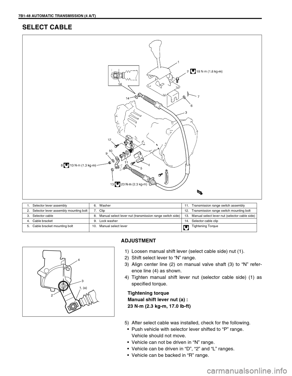
SELECT CABLE
ADJUSTMENT
1) Loosen manual shift lever (select cable side) nut (1).
2) Shift select lever to “N” range.
3) Align center line (2) on manual valve shaft (3) to “N” refer-
ence line (4) as shown.
4) Tighten manual shift lever nut (selector cable side) (1) as
specified torque.
Tightening torque
Manual shift lever nut (a) :
23 N·m (2.3 kg-m, 17.0 lb-ft)
5) After select cable was installed, check for the following.
•Push vehicle with selector lever shifted to “P” range.
Vehicle should not move.
•Vehicle can not be driven in “N” range.
•Vehicle can be driven in “D”, “2” and “L” ranges.
•Vehicle can be backed in “R” range.
1. Selector lever assembly 6. Washer 11. Transmission range switch assembly
2. Selector lever assembly mounting bolt 7. Clip 12. Transmission range switch mounting bolt
3. Selector cable 8. Manual select lever nut (transmission range switch side) 13. Manual select lever nut (selector cable side)
4. Cable bracket 9. Lock washer 14. Selector cable clip
5. Cable bracket mounting bolt 10. Manual select lever Tightening Torque
24
3
1, (a)