1999 SUZUKI GRAND VITARA front brake
[x] Cancel search: front brakePage 4 of 656
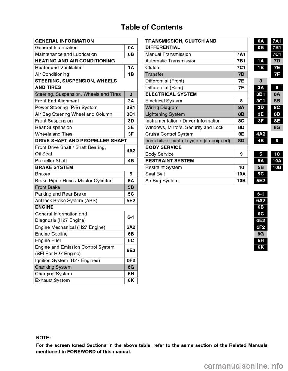
Table of Contents
GENERAL INFORMATION TRANSMISSION, CLUTCH AND
DIFFERENTIAL0A7A1
General Information0A
0B7B1
Maintenance and Lubrication0B
Manual Transmission7A1
7C1
HEATING AND AIR CONDITIONING
Automatic Transmission7B1
1A7D
Heater and Ventilation1A
Clutch7C1
1B7E
Air Conditioning1B
Transfer7D7F
STEERING, SUSPENSION, WHEELS
AND TIRESDifferential (Front)7E
3
Differential (Rear)7F
3A8
Steering, Suspension, Wheels and Tires3 ELECTRICAL SYSTEM3B18A
Front End Alignment3A
Electrical System8
3C18B
Power Steering (P/S) System3B1
Wiring Diagram8A3D8C
Air Bag Steering Wheel and Column3C1
Lightening System8B3E8D
Front Suspension3D
Instrumentation / Driver Information8C
3F8E
Rear Suspension3E
Windows, Mirrors, Security and Lock8D
8G
Wheels and Tires3F
Cruise Control System8E
4A2
DRIVE SHAFT AND PROPELLER SHAFT
Immobilizer control system (if equipped)8G4B9
Front Drive Shaft / Shaft Bearing,
Oil Seal4A2BODY SERVICE
Body Service9
510
Propeller Shaft4B RESTRAINT SYSTEM
5A10A
BRAKE SYSTEM
Restraint System10
5B10B
Brakes5
Seat Belt10A
5C
Brake Pipe / Hose / Master Cylinder5A
Air Bag System10B
5E2
Front Brake5B
Parking and Rear Brake5C
6-1
Antilock Brake System (ABS)5E2
6A2
ENGINE
6B
General Information and
Diagnosis (H27 Engine)6-1
6C
6E2
Engine Mechanical (H27 Engine)6A2
6F2
Engine Cooling6B
6G
Engine Fuel6C
6H
Engine and Emission Control System
(SFI For H27 Engine)6E2
6K
Ignition System (H27 Engines)6F2
Cranking System6G
Charging System6H
Exhaust System6K
NOTE:
For the screen toned Sections in the above table, refer to the same section of the Related Manuals
mentioned in FOREWORD of this manual.
Page 108 of 656
BRAKES PIPE/HOSE/MASTER CYLINDER 5A-1
5A
SECTION 5A
BRAKES PIPE/HOSE/MASTER CYLINDER
CONTENTS
General Description ....................................... 5A-2
Master Cylinder Assembly............................ 5A-2
On-Vehicle Service......................................... 5A-3
Front Brake Hose/Pipe ................................. 5A-3
Master Cylinder Reservoir ............................ 5A-6Master Cylinder Assembly ........................... 5A-7
Brake Booster .............................................. 5A-8
Tightening Torque Specification ................ 5A-10
Special Tool .................................................. 5A-10
WARNING:
For vehicles equipped with Supplemental Restraint (Air Bag) System:
Service on and around the air bag system components or wiring must be performed only by an
authorized SUZUKI dealer. Refer to “Air Bag System Components and Wiring Location View” under
“General Description” in air bag system section in order to confirm whether you are performing ser-
vice on or near the air bag system components or wiring. Please observe all WARNINGS and “Ser-
vice Precautions” under “On-Vehicle Service” in air bag system section before performing service
on or around the air bag system components or wiring. Failure to follow WARNINGS could result in
unintentional activation of the system or could render the system inoperative. Either of these two
conditions may result in severe injury.
Technical service work must be started at least 90 seconds after the ignition switch is turned to the
“LOCK” position and the negative cable is disconnected from the battery. Otherwise, the system
may be activated by reserve energy in the Sensing and Diagnostic Module (SDM).
NOTE:
For the descriptions (items) not found in this section, refer to the same section of the Service Man-
ual mentioned in the FOREWORD of this manual.
All brake fasteners are important attaching parts in that they could affect the performance of vital
parts and systems, and/or could result in major repair expense. They must be replaced with one of
same part number or with an equivalent part if replacement becomes necessary. Do not use a
replacement part of lesser quality or substitute design. Torque values must be used as specified
during reassembly to assure proper retention of all parts. There is to be no welding as it may result
in extensive damage and weakening of the metal.
Page 109 of 656
5A-2 BRAKES PIPE/HOSE/MASTER CYLINDER
General Description
Master Cylinder Assembly
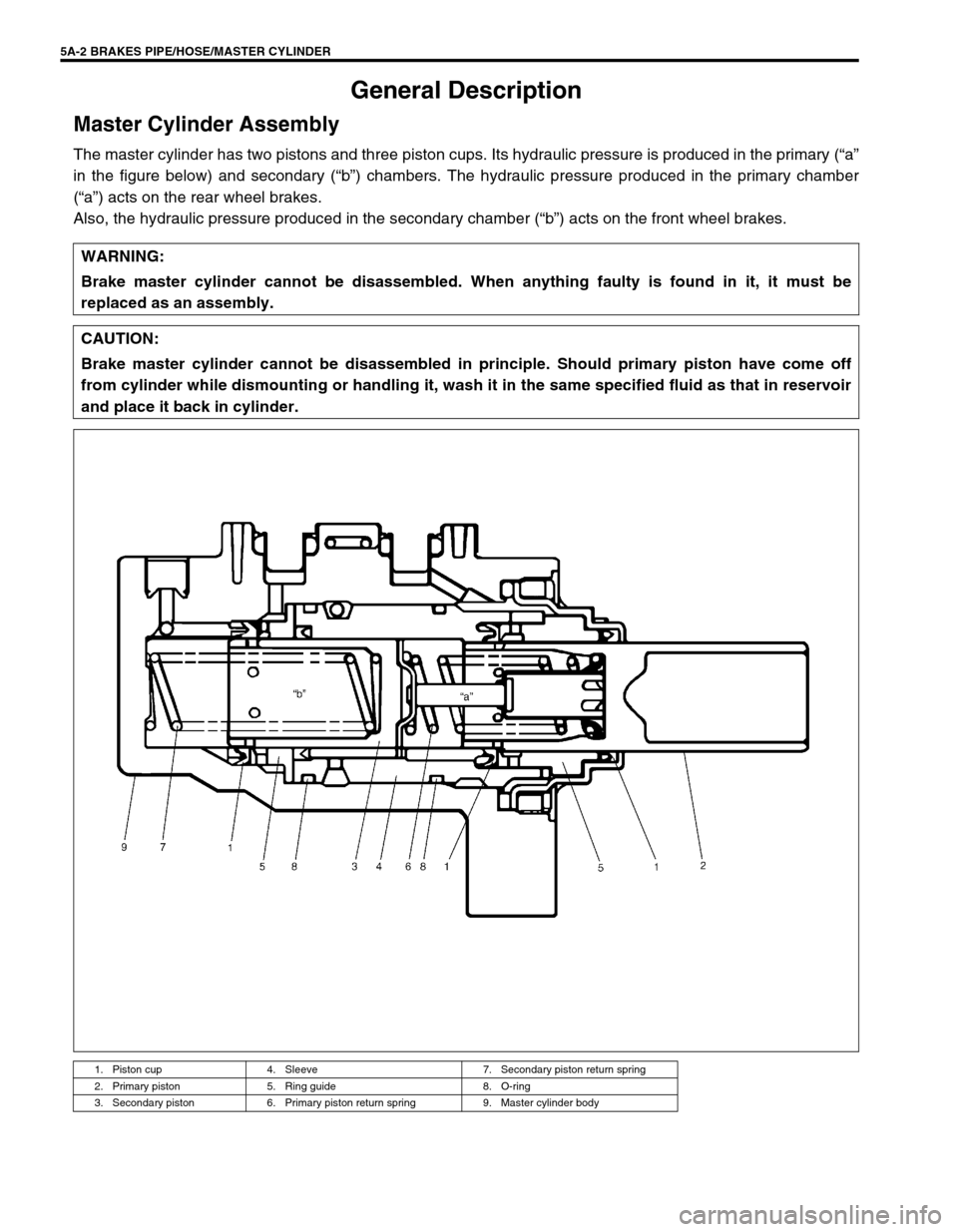
The master cylinder has two pistons and three piston cups. Its hydraulic pressure is produced in the primary (“a”
in the figure below) and secondary (“b”) chambers. The hydraulic pressure produced in the primary chamber
(“a”) acts on the rear wheel brakes.
Also, the hydraulic pressure produced in the secondary chamber (“b”) acts on the front wheel brakes.
WARNING:
Brake master cylinder cannot be disassembled. When anything faulty is found in it, it must be
replaced as an assembly.
CAUTION:
Brake master cylinder cannot be disassembled in principle. Should primary piston have come off
from cylinder while dismounting or handling it, wash it in the same specified fluid as that in reservoir
and place it back in cylinder.
1. Piston cup 4. Sleeve 7. Secondary piston return spring
2. Primary piston 5. Ring guide 8. O-ring
3. Secondary piston 6. Primary piston return spring 9. Master cylinder body
Page 110 of 656
BRAKES PIPE/HOSE/MASTER CYLINDER 5A-3
On-Vehicle Service
Front Brake Hose/Pipe
REMOVAL
1) Raise and suitably support vehicle. Remove tire and wheel.
This operation is not necessary when removing pipes connecting master cylinder and flexible hose.
2) Clean dirt and foreign material from both hose end or pipe end fittings. Remove brake hose or pipe.
INSTALLATION
1) Reverse removal procedure for brake hose and pipe installation procedure.
For installation, make sure that steering wheel is in straightforward position and hose has no twist or kink.
Check to make sure that hose doesn't contact any part of suspension, both in extreme right and extreme left
turn conditions. If it does at any point, remove and correct. Fill and maintain brake fluid level in reservoir.
Bleed brake system.
2) Perform brake test and check installed part for fluid leakage.
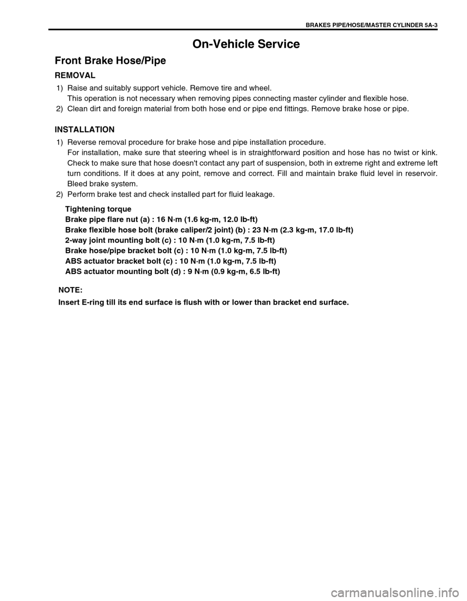
Tightening torque
Brake pipe flare nut (a) : 16 N·m (1.6 kg-m, 12.0 lb-ft)
Brake flexible hose bolt (brake caliper/2 joint) (b) : 23 N·m (2.3 kg-m, 17.0 lb-ft)
2-way joint mounting bolt (c) : 10 N·m (1.0 kg-m, 7.5 lb-ft)
Brake hose/pipe bracket bolt (c) : 10 N·m (1.0 kg-m, 7.5 lb-ft)
ABS actuator bracket bolt (c) : 10 N·m (1.0 kg-m, 7.5 lb-ft)
ABS actuator mounting bolt (d) : 9 N·m (0.9 kg-m, 6.5 lb-ft)
NOTE:
Insert E-ring till its end surface is flush with or lower than bracket end surface.
Page 111 of 656
![SUZUKI GRAND VITARA 1999 2.G Owners Manual 5A-4 BRAKES PIPE/HOSE/MASTER CYLINDER
For RH steering vehicle
[D]: View D 1. E-ring
[a]: Clamp a 2. Flexible hose
[b]: Clamp b 3. Hose washer
[c]: Clamp d 4. Hose bolt
T: Top side 5. Brake caliper
F: SUZUKI GRAND VITARA 1999 2.G Owners Manual 5A-4 BRAKES PIPE/HOSE/MASTER CYLINDER
For RH steering vehicle
[D]: View D 1. E-ring
[a]: Clamp a 2. Flexible hose
[b]: Clamp b 3. Hose washer
[c]: Clamp d 4. Hose bolt
T: Top side 5. Brake caliper
F:](/manual-img/20/7583/w960_7583-110.png)
5A-4 BRAKES PIPE/HOSE/MASTER CYLINDER
For RH steering vehicle
[D]: View D 1. E-ring
[a]: Clamp a 2. Flexible hose
[b]: Clamp b 3. Hose washer
[c]: Clamp d 4. Hose bolt
T: Top side 5. Brake caliper
F: Front side 6. 2 way joint
Page 112 of 656
![SUZUKI GRAND VITARA 1999 2.G Owners Manual BRAKES PIPE/HOSE/MASTER CYLINDER 5A-5
For LH steering vehicle
[D]: View D 1. E-ring
[a]: Clamp a 2. Flexible hose
[b]: Clamp b 3. Hose washer
[d]: Clamp d 4. Hose bolt
T: Top side 5. Brake caliper
F: SUZUKI GRAND VITARA 1999 2.G Owners Manual BRAKES PIPE/HOSE/MASTER CYLINDER 5A-5
For LH steering vehicle
[D]: View D 1. E-ring
[a]: Clamp a 2. Flexible hose
[b]: Clamp b 3. Hose washer
[d]: Clamp d 4. Hose bolt
T: Top side 5. Brake caliper
F:](/manual-img/20/7583/w960_7583-111.png)
BRAKES PIPE/HOSE/MASTER CYLINDER 5A-5
For LH steering vehicle
[D]: View D 1. E-ring
[a]: Clamp a 2. Flexible hose
[b]: Clamp b 3. Hose washer
[d]: Clamp d 4. Hose bolt
T: Top side 5. Brake caliper
F: Front side 6. 2 way joint
Page 117 of 656
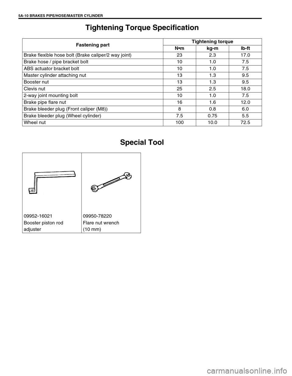
5A-10 BRAKES PIPE/HOSE/MASTER CYLINDER
Tightening Torque Specification
Special Tool
Fastening partTightening torque
Nm kg-m lb-ft
Brake flexible hose bolt (Brake caliper/2 way joint) 23 2.3 17.0
Brake hose / pipe bracket bolt 10 1.0 7.5
ABS actuator bracket bolt 10 1.0 7.5
Master cylinder attaching nut 13 1.3 9.5
Booster nut 13 1.3 9.5
Clevis nut 25 2.5 18.0
2-way joint mounting bolt 10 1.0 7.5
Brake pipe flare nut 16 1.6 12.0
Brake bleeder plug (Front caliper (M8)) 8 0.8 6.0
Brake bleeder plug (Wheel cylinder) 7.5 0.75 5.5
Wheel nut 100 10.0 72.5
09952-16021 09950-78220
Booster piston rod
adjusterFlare nut wrench
(10 mm)
Page 126 of 656

ANTILOCK BRAKE SYSTEM (ABS) 5E2-1
5E2
SECTION 5E2
ANTILOCK BRAKE SYSTEM (ABS)
CONTENTS
General Description ..................................... 5E2-3
Components/Parts Location ....................... 5E2-3
ABS Hydraulic Unit/control Module
Assembly .................................................... 5E2-4
Self-diagnosis function ........................... 5E2-4
Fail-safe function .................................... 5E2-5
Diagnosis ...................................................... 5E2-5
Precautions in Diagnosing Troubles .......... 5E2-5
ABS Diagnostic Flow Table ........................ 5E2-6
ABS Warning Lamp Check ........................ 5E2-9
EBD Warning Lamp (Brake Warning Lamp)
Check ......................................................... 5E2-9
Diagnostic Trouble Code (DTC) Check
(Using ABS Warning Lamp) ..................... 5E2-10
Diagnostic Trouble Code (DTC) Check
(Using SUZUKI Scan Tool) ...................... 5E2-11
Diagnostic Trouble Code (DTC)
Clearance ................................................. 5E2-11
Diagnostic Trouble Code (DTC) Table ..... 5E2-12
System Circuit .......................................... 5E2-14Table-A ABS Warning Lamp Circuit Check
– Lamp Does Not Come “ON” at Ignition
Switch ON ................................................ 5E2-15
Table-B ABS Warning Lamp Circuit Check
– Lamp Comes “ON” Steady.................... 5E2-16
Table-C ABS Warning Lamp Circuit Check
– The Lamp Flashes Continuously While
Ignition Switch Is ON ................................ 5E2-17
Table-D Code (DTC) Is Not Outputted
Even with Diagnosis Switch Terminal
Connected to Ground............................... 5E2-18
Table-E EBD Warning Lamp (Brake
Warning Lamp) Check – Lamp Comes
“ON” Steady ............................................. 5E2-19
DTC C1015 (DTC 15) – G Sensor Circuit
and 4WD Lamp Circuit ............................. 5E2-20
DTC C1021 (DTC 21), DTC C1022
(DTC 22) – Right-Front Wheel Speed
Sensor Circuit or Sensor Ring ................. 5E2-22
DTC C1025 (DTC 25), DTC C1026
(DTC 26) – Left-Front Wheel Speed WARNING:
For vehicles equipped with Supplemental Restraint (Air Bag) System:
Service on and around the air bag system components or wiring must be performed only by an
authorized SUZUKI dealer. Refer to “Air Bag System Components and Wiring Location View” under
“General Description” in air bag system section in order to confirm whether you are performing ser-
vice on or near the air bag system components or wiring. Please observe all WARNINGS and “Ser-
vice Precautions” under “On-Vehicle Service” in air bag system section before performing service
on or around the air bag system components or wiring. Failure to follow WARNINGS could result in
unintentional activation of the system or could render the system inoperative. Either of these two
conditions may result in severe injury.
Technical service work must be started at least 90 seconds after the ignition switch is turned to the
“LOCK” position and the negative cable is disconnected from the battery. Otherwise, the system
may be activated by reserve energy in the Sensing and Diagnostic Module (SDM).
NOTE:
For the descriptions (items) not found in this section, refer to Section 5E1 of the Service Manual
mentioned in the FOREWORD of this manual.
All brake fasteners are important attaching parts in that they could affect the performance of vital
parts and systems, and/or could result in major repair expense. They must be replaced with one of
same part number or with an equivalent part if replacement becomes necessary. Do not use a
replacement part of lesser quality or substitute design. Torque values must be used as specified
during reassembly to assure proper retention of all parts. There is to be no welding as it may result
in extensive damage and weakening of the metal.