Page 72 of 656

POWER STEERING (P/S) SYSTEM 3B1-1
3B1
SECTION 3B1
POWER STEERING (P/S) SYSTEM
CONTENTS
General Description ......................................3B1-2
Power Steering (P/S) Pump ........................ 3B1-2
Diagnosis .......................................................3B1-2
Power Steering Pump Drive Belt ................. 3B1-2
Belt inspection ......................................... 3B1-2Belt tension check ................................... 3B1-2
Belt tension adjustment ........................... 3B1-2
Hydraulic Pressure in P/S Circuit ................ 3B1-3
Hydraulic pressure check ........................ 3B1-3 WARNING:
For vehicles equipped with Supplemental Restraint (Air Bag) System:
Service on and around the air bag system components or wiring must be performed only by an
authorized SUZUKI dealer. Refer to “Air Bag System Components and Wiring Location View” under
“General Description” in air bag system section in order to confirm whether you are performing ser-
vice on or near the air bag system components or wiring. Please observe all WARNINGS and “Ser-
vice Precautions” under “On-Vehicle Service” in air bag system section before performing service
on or around the air bag system components or wiring. Failure to follow WARNINGS could result in
unintentional activation of the system or could render the system inoperative. Either of these two
conditions may result in severe injury.
Technical service work must be started at least 90 seconds after the ignition switch is turned to the
“LOCK” position and the negative cable is disconnected from the battery. Otherwise, the system
may be activated by reserve energy in the Sensing and Diagnostic Module (SDM).
NOTE:
For the descriptions (items) not found in this section, refer to the same section of the Service Man-
ual mentioned in the FOREWORD of this manual.
Some parts in the Power Steering Gear Box cannot be disassembled or adjusted. For detailed infor-
mation, refer to the description of “POWER STEERING GEAR BOX ASSEMBLY”.
All steering gear fasteners are important attaching parts in that they could affect the performance of
vital parts and systems, and/or could result in major repair expense. They must be replaced with
one of the same part number or with an equivalent part if replacement becomes necessary. Do not
use a replacement part of lesser quality or substitute design. Torque values must be used as speci-
fied during reassembly to assure proper retention of these parts.
Page 74 of 656

POWER STEERING (P/S) SYSTEM 3B1-3
Hydraulic Pressure in P/S Circuit
Hydraulic pressure check
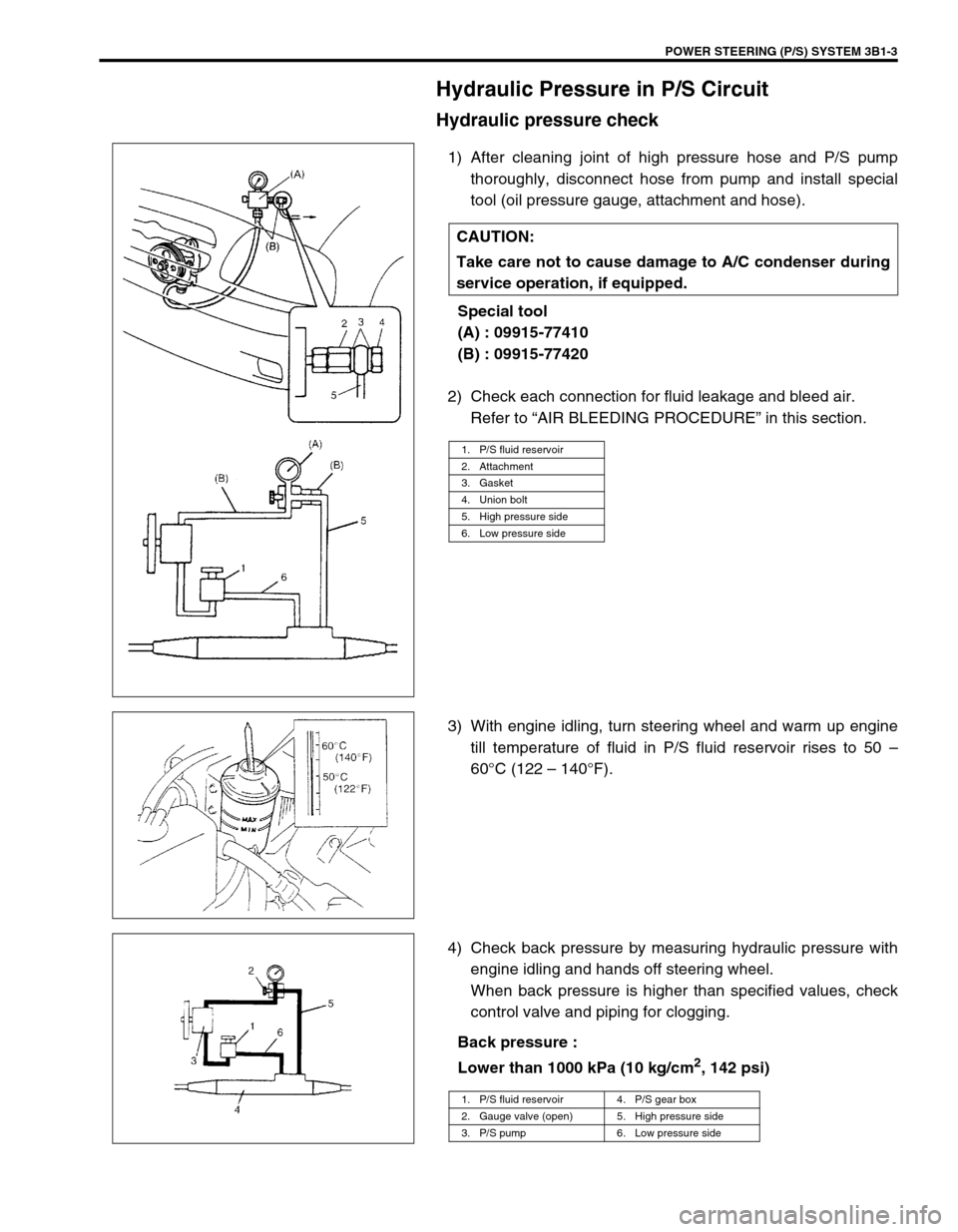
1) After cleaning joint of high pressure hose and P/S pump
thoroughly, disconnect hose from pump and install special
tool (oil pressure gauge, attachment and hose).
Special tool
(A) : 09915-77410
(B) : 09915-77420
2) Check each connection for fluid leakage and bleed air.
Refer to “AIR BLEEDING PROCEDURE” in this section.
3) With engine idling, turn steering wheel and warm up engine
till temperature of fluid in P/S fluid reservoir rises to 50 –
60°C (122 – 140°F).
4) Check back pressure by measuring hydraulic pressure with
engine idling and hands off steering wheel.
When back pressure is higher than specified values, check
control valve and piping for clogging.
Back pressure :
Lower than 1000 kPa (10 kg/cm
2, 142 psi) CAUTION:
Take care not to cause damage to A/C condenser during
service operation, if equipped.
1. P/S fluid reservoir
2. Attachment
3. Gasket
4. Union bolt
5. High pressure side
6. Low pressure side
1. P/S fluid reservoir 4. P/S gear box
2. Gauge valve (open) 5. High pressure side
3. P/S pump 6. Low pressure side
Page 75 of 656

3B1-4 POWER STEERING (P/S) SYSTEM
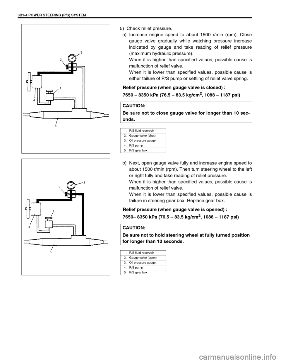
5) Check relief pressure.
a) Increase engine speed to about 1500 r/min (rpm). Close
gauge valve gradually while watching pressure increase
indicated by gauge and take reading of relief pressure
(maximum hydraulic pressure).
When it is higher than specified values, possible cause is
malfunction of relief valve.
When it is lower than specified values, possible cause is
either failure of P/S pump or settling of relief valve spring.
Relief pressure (when gauge valve is closed) :
7650 – 8350 kPa (76.5 – 83.5 kg/cm
2, 1088 – 1187 psi)
b) Next, open gauge valve fully and increase engine speed to
about 1500 r/min (rpm). Then turn steering wheel to the left
or right fully and take reading of relief pressure.
When it is higher than specified values, possible cause is
malfunction of relief valve.
When it is lower than specified values, possible cause is
failure in steering gear box. Replace gear box.
Relief pressure (when gauge valve is opened) :
7650– 8350 kPa (76.5 – 83.5 kg/cm
2, 1088 – 1187 psi) CAUTION:
Be sure not to close gauge valve for longer than 10 sec-
onds.
1. P/S fluid reservoir
2. Gauge valve (shut)
3. Oil pressure gauge
4. P/S pump
5. P/S gear box
CAUTION:
Be sure not to hold steering wheel at fully turned position
for longer than 10 seconds.
1. P/S fluid reservoir
2. Gauge valve (open)
3. Oil pressure gauge
4. P/S pump
5. P/S gear box
Page 166 of 656

ENGINE GENERAL INFORMATION AND DIAGNOSIS (H27 ENGINE) 6-1-5
Fuel Pressure Relief Procedure
After making sure that engine is cold, relief fuel pressure as fol-
lows.
1) Place transmission gear shift lever in “Neutral” (shift selector
lever to “P” range for A/T vehicle), set parking brake, and
block drive wheels.
2) Remove fuel pump relay (1) from its connector.
3) Remove fuel filler cap to release fuel vapor pressure in fuel
tank and then reinstall it.
4) Start engine and run it till it stops for lack of fuel. Repeat
cranking engine 2 – 3 times of about 3 seconds each time to
dissipate fuel pressure in lines. Fuel connections are now
safe for servicing.
5) Upon completion of servicing, install fuel pump relay to relay
box.
Fuel Leakage Check Procedure
After performing any service on fuel system, check to make sure
that there are no fuel leakages as follows.
1) Turn ON ignition switch for 3 seconds (to operate fuel pump)
and then turn it OFF.
Repeat this (ON and OFF) 3 or 4 times and apply fuel pres-
sure to fuel line (till fuel pressure is felt by hand placed on
fuel return hose).
2) In this state, check to see that there are no fuel leakages
from any part of fuel system. CAUTION:
This work must not be done when engine is hot. If done
so, it may cause adverse effect to catalyst.
[A] : Left hand steering vehicle
[B] : Right hand steering vehicle
2. Fuse box