Page 759 of 1456
11) Install wheel and tighten wheel nuts to speci-
fied torque.
Tightening torque:
88
±10 N´m (9±1 kg-m, 65±7 ft-lb)
2. Rear Axle
A: REMOVAL
1. DISC BRAKE
1) Disconnect ground cable from battery.
2) Jack-up vehicle, and remove rear wheel cap
and wheels.
CAUTION:
Be sure to loosen and retighten axle nut after
removing wheel from vehicle. Failure to follow
this rule may damage wheel bearings.
3) Unlock axle nut.
4) Remove axle nut using a socket wrench.
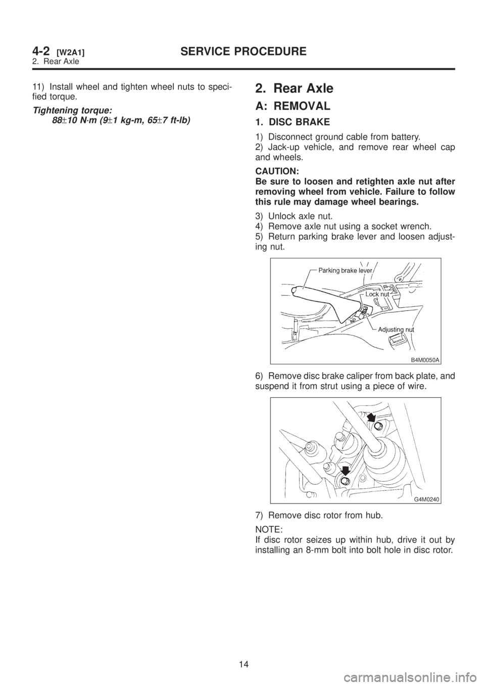
5) Return parking brake lever and loosen adjust-
ing nut.
B4M0050A
6) Remove disc brake caliper from back plate, and
suspend it from strut using a piece of wire.
G4M0240
7) Remove disc rotor from hub.
NOTE:
If disc rotor seizes up within hub, drive it out by
installing an 8-mm bolt into bolt hole in disc rotor.
14
4-2[W2A1]SERVICE PROCEDURE
2. Rear Axle
Page 760 of 1456
11) Install wheel and tighten wheel nuts to speci-
fied torque.
Tightening torque:
88
±10 N´m (9±1 kg-m, 65±7 ft-lb)
2. Rear Axle
A: REMOVAL
1. DISC BRAKE
1) Disconnect ground cable from battery.
2) Jack-up vehicle, and remove rear wheel cap
and wheels.
CAUTION:
Be sure to loosen and retighten axle nut after
removing wheel from vehicle. Failure to follow
this rule may damage wheel bearings.
3) Unlock axle nut.
4) Remove axle nut using a socket wrench.
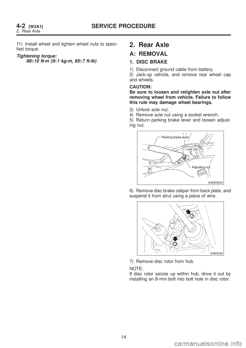
5) Return parking brake lever and loosen adjust-
ing nut.
B4M0050A
6) Remove disc brake caliper from back plate, and
suspend it from strut using a piece of wire.
G4M0240
7) Remove disc rotor from hub.
NOTE:
If disc rotor seizes up within hub, drive it out by
installing an 8-mm bolt into bolt hole in disc rotor.
14
4-2[W2A1]SERVICE PROCEDURE
2. Rear Axle
Page 766 of 1456

11) Using ST1 and ST2, press bearing into hub.
ST1 927080000 HUB STAND
ST2 927450000 HUB INSTALLER
G4M0262
E: INSTALLATION
1. DISC BRAKE
1) Connect rear housing assembly and strut
assembly.
CAUTION:
Use a new self-locking nut.
Tightening torque:
147
±15 N´m (15±1.5 kg-m, 108±11 ft-lb)
2) Fit BJ (bell joint) to rear housing splines.
CAUTION:
Be careful not to damage inner oil seal lip.
3) Connect rear housing assembly to lateral link
assembly.
CAUTION:
Use a new self-locking nut.
Tightening torque:
137
±20 N´m (14±2 kg-m, 101±14 ft-lb)
G4M0245
4) Connect rear housing assembly to trailing link
assembly.
CAUTION:
Use a new self-locking nut.
Tightening torque:
98 Ð 127 N´m (10 Ð 13 kg-m, 72 Ð 94
ft-lb)
G4M0246
5) Connect parking brake cable to parking brake.
6) Install disc rotor on rear housing assembly.
7) Install disc brake caliper on back plate.
Tightening torque:
52
±6 N´m (5.3±0.6 kg-m, 38.3±4.3 ft-lb)
G4M0240
8) Install rear speed sensor to back plate (only
vehicle equipped with ABS).
G4M0266
9) Bleed air from brake system.
[W11B0].>
10) Adjust parking brake lever stroke by turning
adjuster.
11) Move brake lever back to apply brakes. While
depressing brake pedal, tighten axle nut using a
20
4-2[W2E1]SERVICE PROCEDURE
2. Rear Axle
Page 879 of 1456
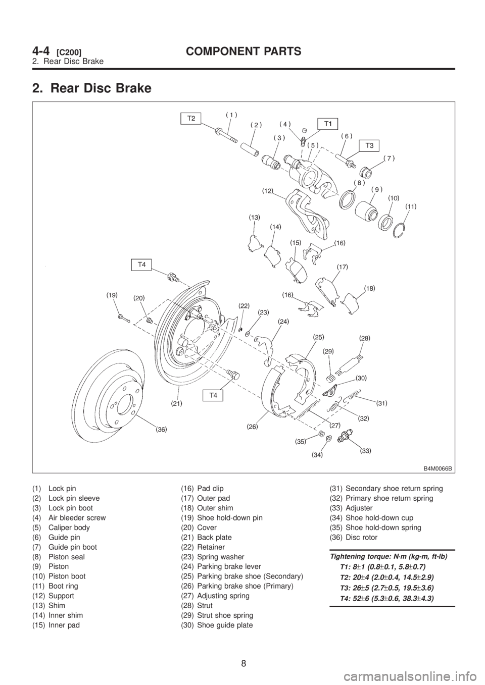
2. Rear Disc Brake
B4M0066B
(1) Lock pin
(2) Lock pin sleeve
(3) Lock pin boot
(4) Air bleeder screw
(5) Caliper body
(6) Guide pin
(7) Guide pin boot
(8) Piston seal
(9) Piston
(10) Piston boot
(11) Boot ring
(12) Support
(13) Shim
(14) Inner shim
(15) Inner pad(16) Pad clip
(17) Outer pad
(18) Outer shim
(19) Shoe hold-down pin
(20) Cover
(21) Back plate
(22) Retainer
(23) Spring washer
(24) Parking brake lever
(25) Parking brake shoe (Secondary)
(26) Parking brake shoe (Primary)
(27) Adjusting spring
(28) Strut
(29) Strut shoe spring
(30) Shoe guide plate(31) Secondary shoe return spring
(32) Primary shoe return spring
(33) Adjuster
(34) Shoe hold-down cup
(35) Shoe hold-down spring
(36) Disc rotor
Tightening torque: N´m (kg-m, ft-lb)
T1:
8±1 (0.8±0.1, 5.8±0.7)
T2:20±4 (2.0±0.4, 14.5±2.9)
T3:26±5 (2.7±0.5, 19.5±3.6)
T4:52±6 (5.3±0.6, 38.3±4.3)
8
4-4[C200]COMPONENT PARTS
2. Rear Disc Brake
Page 898 of 1456
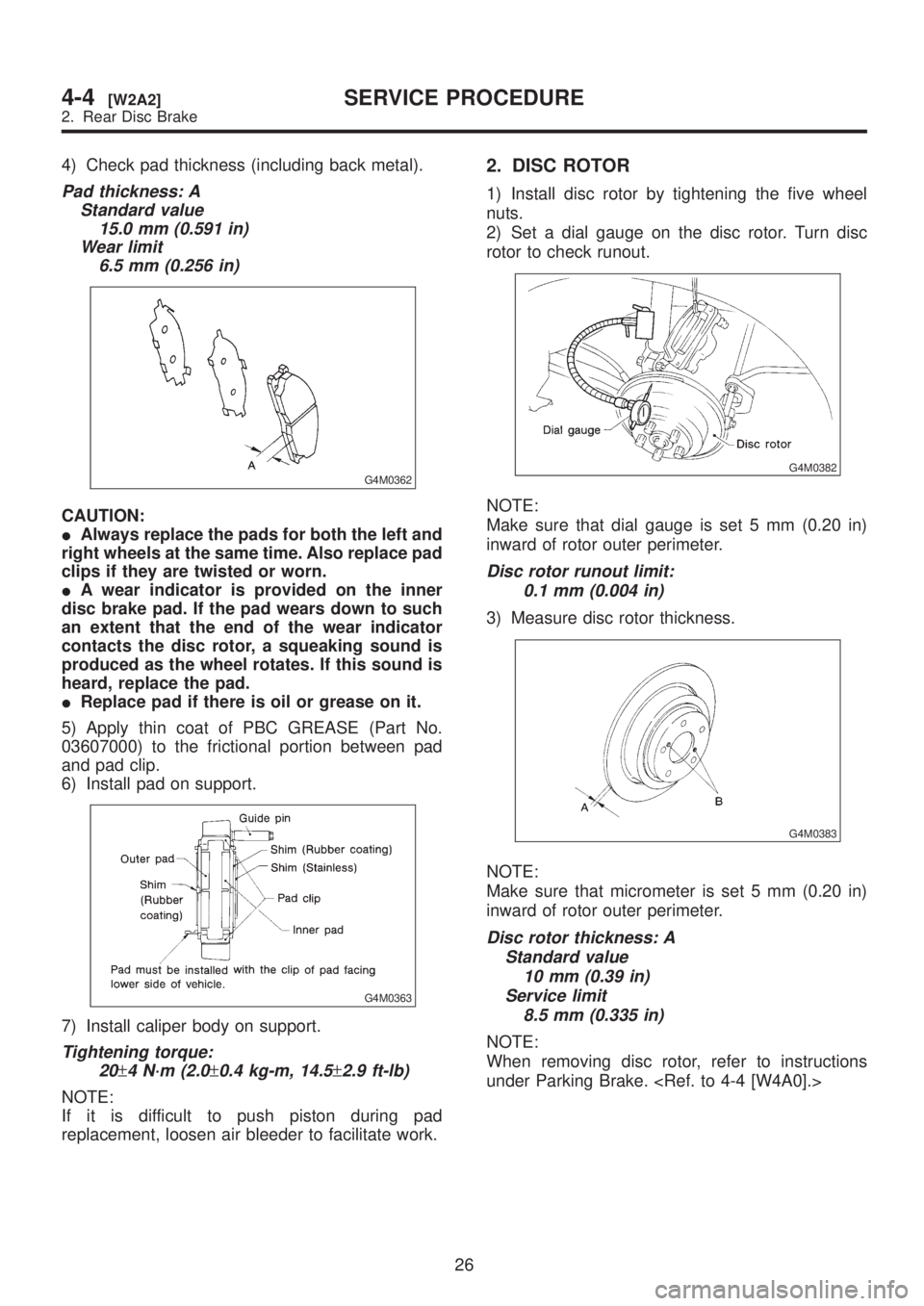
4) Check pad thickness (including back metal).
Pad thickness: A
Standard value
15.0 mm (0.591 in)
Wear limit
6.5 mm (0.256 in)
G4M0362
CAUTION:
IAlways replace the pads for both the left and
right wheels at the same time. Also replace pad
clips if they are twisted or worn.
IA wear indicator is provided on the inner
disc brake pad. If the pad wears down to such
an extent that the end of the wear indicator
contacts the disc rotor, a squeaking sound is
produced as the wheel rotates. If this sound is
heard, replace the pad.
IReplace pad if there is oil or grease on it.
5) Apply thin coat of PBC GREASE (Part No.
03607000) to the frictional portion between pad
and pad clip.
6) Install pad on support.
G4M0363
7) Install caliper body on support.
Tightening torque:
20
±4 N´m (2.0±0.4 kg-m, 14.5±2.9 ft-lb)
NOTE:
If it is difficult to push piston during pad
replacement, loosen air bleeder to facilitate work.
2. DISC ROTOR
1) Install disc rotor by tightening the five wheel
nuts.
2) Set a dial gauge on the disc rotor. Turn disc
rotor to check runout.
G4M0382
NOTE:
Make sure that dial gauge is set 5 mm (0.20 in)
inward of rotor outer perimeter.
Disc rotor runout limit:
0.1 mm (0.004 in)
3) Measure disc rotor thickness.
G4M0383
NOTE:
Make sure that micrometer is set 5 mm (0.20 in)
inward of rotor outer perimeter.
Disc rotor thickness: A
Standard value
10 mm (0.39 in)
Service limit
8.5 mm (0.335 in)
NOTE:
When removing disc rotor, refer to instructions
under Parking Brake.
26
4-4[W2A2]SERVICE PROCEDURE
2. Rear Disc Brake
Page 899 of 1456
B: REMOVAL
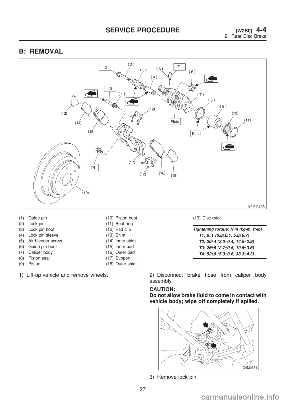
B4M1124A
(1) Guide pin
(2) Lock pin
(3) Lock pin boot
(4) Lock pin sleeve
(5) Air bleeder screw
(6) Guide pin boot
(7) Caliper body
(8) Piston seal
(9) Piston(10) Piston boot
(11) Boot ring
(12) Pad clip
(13) Shim
(14) Inner shim
(15) Inner pad
(16) Outer pad
(17) Support
(18) Outer shim(19) Disc rotor
Tightening torque: N´m (kg-m, ft-lb)
T1:
8±1 (0.8±0.1, 5.8±0.7)
T2:20±4 (2.0±0.4, 14.5±2.9)
T3:26±5 (2.7±0.5, 19.5±3.6)
T4:52±6 (5.3±0.6, 38.3±4.3)
1) Lift-up vehicle and remove wheels. 2) Disconnect brake hose from caliper body
assembly.
CAUTION:
Do not allow brake fluid to come in contact with
vehicle body; wipe off completely if spilled.
G4M0384
3) Remove lock pin.
27
[W2B0]4-4SERVICE PROCEDURE
2. Rear Disc Brake
Page 900 of 1456
4) Raise caliper body and move it toward vehicle
center to separate it from support.
5) Remove support from back plate.
NOTE:
Remove support only when replacing it or the rotor.
It need not be removed when servicing caliper
body assembly.
6) Clean mud and foreign particles from caliper
body assembly and support.
CAUTION:
Be careful not to allow foreign particles to enter
inlet (at brake hose connector).
C: DISASSEMBLY
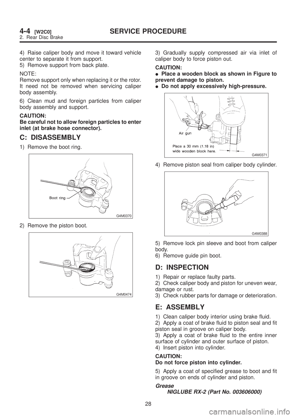
1) Remove the boot ring.
G4M0370
2) Remove the piston boot.
G4M0474
3) Gradually supply compressed air via inlet of
caliper body to force piston out.
CAUTION:
IPlace a wooden block as shown in Figure to
prevent damage to piston.
IDo not apply excessively high-pressure.
G4M0371
4) Remove piston seal from caliper body cylinder.
G4M0388
5) Remove lock pin sleeve and boot from caliper
body.
6) Remove guide pin boot.
D: INSPECTION
1) Repair or replace faulty parts.
2) Check caliper body and piston for uneven wear,
damage or rust.
3) Check rubber parts for damage or deterioration.
E: ASSEMBLY
1) Clean caliper body interior using brake fluid.
2) Apply a coat of brake fluid to piston seal and fit
piston seal in groove on caliper body.
3) Apply a coat of brake fluid to the entire inner
surface of cylinder and outer surface of piston.
4) Insert piston into cylinder.
CAUTION:
Do not force piston into cylinder.
5) Apply a coat of specified grease to boot and fit
in groove on ends of cylinder and piston.
Grease
NIGLUBE RX-2 (Part No. 003606000)
28
4-4[W2C0]SERVICE PROCEDURE
2. Rear Disc Brake
Page 901 of 1456
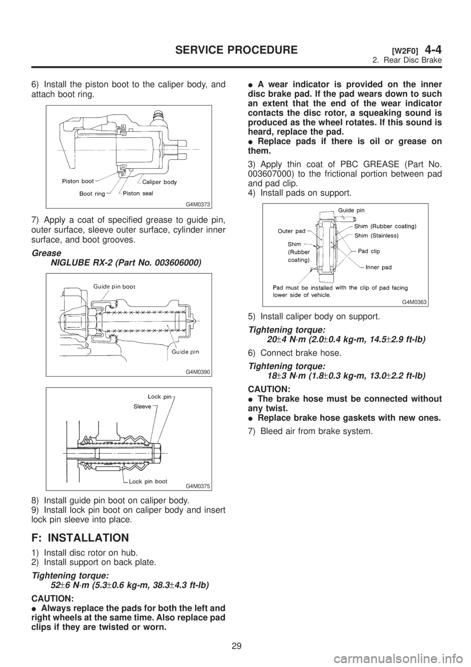
6) Install the piston boot to the caliper body, and
attach boot ring.
G4M0373
7) Apply a coat of specified grease to guide pin,
outer surface, sleeve outer surface, cylinder inner
surface, and boot grooves.
Grease
NIGLUBE RX-2 (Part No. 003606000)
G4M0390
G4M0375
8) Install guide pin boot on caliper body.
9) Install lock pin boot on caliper body and insert
lock pin sleeve into place.
F: INSTALLATION
1) Install disc rotor on hub.
2) Install support on back plate.
Tightening torque:
52
±6 N´m (5.3±0.6 kg-m, 38.3±4.3 ft-lb)
CAUTION:
IAlways replace the pads for both the left and
right wheels at the same time. Also replace pad
clips if they are twisted or worn.IA wear indicator is provided on the inner
disc brake pad. If the pad wears down to such
an extent that the end of the wear indicator
contacts the disc rotor, a squeaking sound is
produced as the wheel rotates. If this sound is
heard, replace the pad.
IReplace pads if there is oil or grease on
them.
3) Apply thin coat of PBC GREASE (Part No.
003607000) to the frictional portion between pad
and pad clip.
4) Install pads on support.
G4M0363
5) Install caliper body on support.
Tightening torque:
20
±4 N´m (2.0±0.4 kg-m, 14.5±2.9 ft-lb)
6) Connect brake hose.
Tightening torque:
18
±3 N´m (1.8±0.3 kg-m, 13.0±2.2 ft-lb)
CAUTION:
IThe brake hose must be connected without
any twist.
IReplace brake hose gaskets with new ones.
7) Bleed air from brake system.
29
[W2F0]4-4SERVICE PROCEDURE
2. Rear Disc Brake