Page 517 of 1456
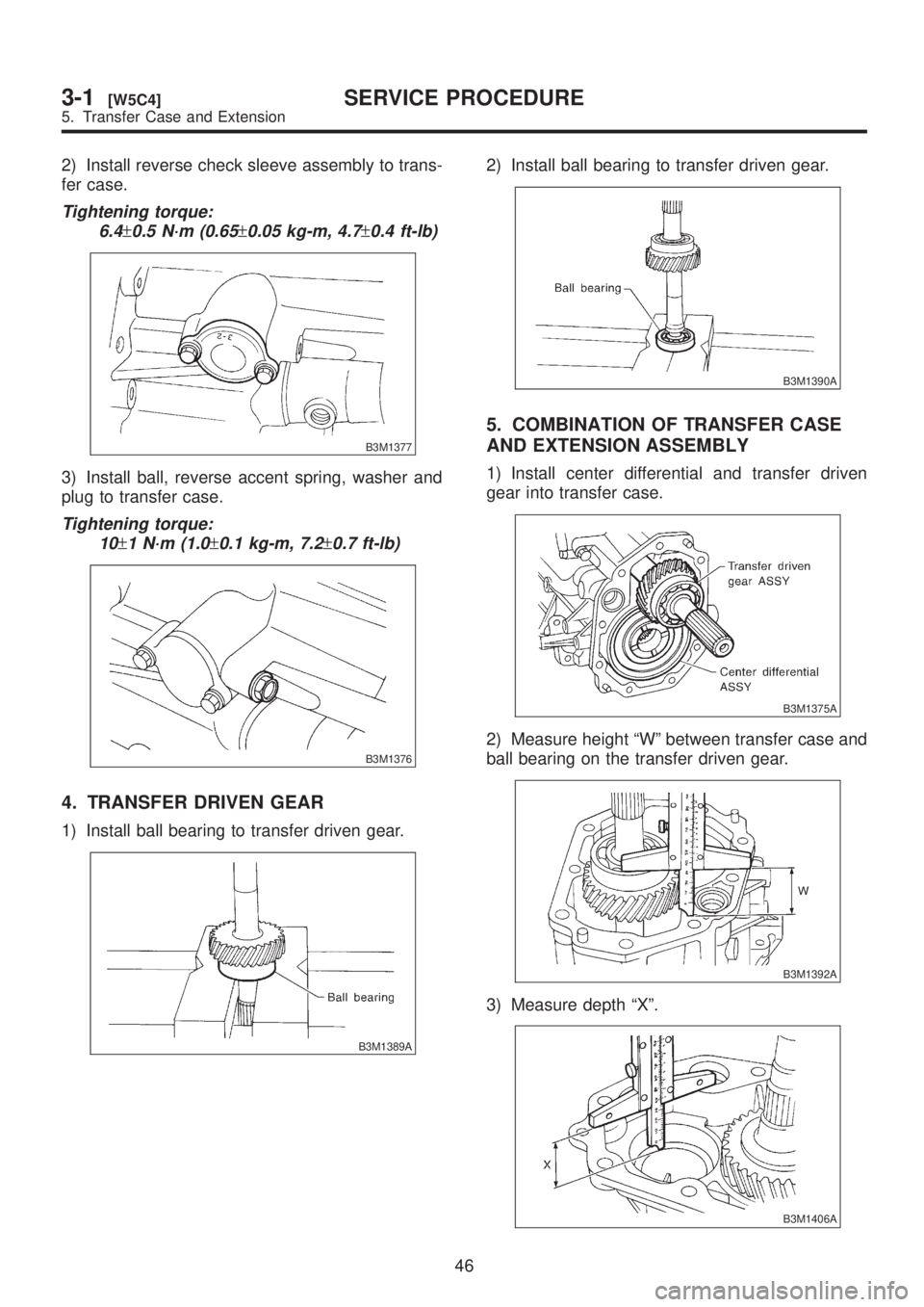
2) Install reverse check sleeve assembly to trans-
fer case.
Tightening torque:
6.4
±0.5 N´m (0.65±0.05 kg-m, 4.7±0.4 ft-lb)
B3M1377
3) Install ball, reverse accent spring, washer and
plug to transfer case.
Tightening torque:
10
±1 N´m (1.0±0.1 kg-m, 7.2±0.7 ft-lb)
B3M1376
4. TRANSFER DRIVEN GEAR
1) Install ball bearing to transfer driven gear.
B3M1389A
2) Install ball bearing to transfer driven gear.
B3M1390A
5. COMBINATION OF TRANSFER CASE
AND EXTENSION ASSEMBLY
1) Install center differential and transfer driven
gear into transfer case.
B3M1375A
2) Measure height ªWº between transfer case and
ball bearing on the transfer driven gear.
B3M1392A
3) Measure depth ªXº.
B3M1406A
46
3-1[W5C4]SERVICE PROCEDURE
5. Transfer Case and Extension
Page 587 of 1456

Checking item Contact pattern Corrective action
Tooth contact
Tooth contact pattern is slightly shifted
toward to under no-load rotation.
[When loaded, contact pattern moves
toward heel.]
B3M0317A
Ð
Face contact
Backlash is too large.This may cause noise and chipping at
tooth ends.
B3M0319
Increase thickness of drive pinion height
adjusting shim in order to bring drive pin-
ion close to crown gear.
B3M0323
Flank contact Backlash is too small. This may cause noise and stepped wear
on surfaces.
B3M0320
Reduce thickness of drive pinion height
adjusting shim in order to move drive
pinion away from crown gear.
B3M0324
Toe contact
(Inside end contact)
Contact areas is small.This may cause chipping at toe.
B3M0321
Adjust as for flank contact.
B3M0324
Heel contact (Outside end contact)
Contact area is small.This may cause chipping at heel ends.
B3M0322
Adjust as for face contact.
B3M0323
: Adjusting direction of drive pinion: Adjusting direction of crown gear
58
3-2[W11C1]SERVICE PROCEDURE
11. Overall Transmission
Page 595 of 1456

(2) Using ST, measure the distance from the oil
pump housing mating surface to the top surface
of the oil pump cover with thrust needle bearing.
ST 398643600 GAUGE
B3M0983A
(3) Calculation of total end play
Select suitable bearing race from among those
listed in this table so that clearance C is in the
0.25 Ð 0.55 mm (0.0098 Ð 0.0217 in) range.
C=(L+G)þ
CClearance between concave portion of high clutch
and end of clutch drum support
LLength from case mating surface to concave por-
tion of high clutch
G Gasket thickness (0.28 mm, 0.0110 in)
Height from housing mating surface to upper sur-
face of clutch drum support
B3M0984A
Thrust needle bearing
Part No. Thickness mm (in)
806528050
806528060
806528070
806528080
806528090
8065281004.1 (0.161)
4.3 (0.169)
4.5 (0.177)
4.7 (0.185)
4.9 (0.193)
5.1 (0.201)
27) Install the oil pump housing assembly.
(1) After completing end play adjustment, insert
the bearing race in the recess of the high clutch.
Attach the thrust needle bearing to the oil pump
cover with vaseline.(2) After correctly installing the gasket to the
case mating surface, carefully install the oil
pump housing assembly. Be careful to avoid hit-
ting the drive pinion against the inside of the
case.
CAUTION:
IBe careful not to damage the seal ring.
IBe sure to use a new gasket.
(3) Install both parts with dowel pins aligned.
Make sure no clearance exists at the mating
surface.
NOTE:
Any clearance suggests a damaged seal ring.
(4) Secure the housing with two nuts.
Tightening torque:
T: 4 1
±3 N´m (4.2±0.3 kg-m, 30.4±2.2 ft-lb)
B3M1068A
3. TORQUE CONVERTER CLUTCH CASE
AND TRANSMISSION CASE
1) Apply proper amount of liquid gasket (THREE
BOND Part No. 1215) to the entire torque con-
verter clutch case mating surface.
NOTE:
Make sure that the rubber seal and seal pipe are
fitted in position.
G3M0394
66
3-2[W11C3]SERVICE PROCEDURE
11. Overall Transmission
Page 599 of 1456

(2) Measure the distance ªº from the transmis-
sion case mating surface to the reduction drive
gear end surface with ST1 and ST2.
= Measured value þ 50 mm
ST1 398643600 GAUGE
ST2 499577000 GAUGE
B3M1114A
(3) Calculation equation:
NOTE:
Add 0.05 mm (0.0020 in) and 0.20 mm (0.0079 in)
thick shims to area ªTº. Calculate formula 2 to
determine ªHº. The calculated ªHº refers to the
shim thickness range. Select shims of suitable
thicknesses within the calculated ªHº range.
T=(L+G)þþH
T : Shim clearance
L : Distance from end of extension case to
end of rear drive shaft
G: Gasket thickness (0.45 mm, 0.0177 in)
: Height from end of transmission case to
end of reduction drive gear
H : Thrust needle bearing thickness
0.05 Ð 0.25 mm (0.0020 Ð 0.0098 in)
Thrust needle bearing
Part No. Thickness mm (in)
806536020
806535030
806535040
806535050
806535060
806535070
8065350903.8 (0.150)
4.0 (0.157)
4.2 (0.165)
4.4 (0.173)
4.6 (0.181)
4.8 (0.189)
5.0 (0.197)
8) Installation of extension case and transmission
case
(1) Attach the selected thrust needle bearing to
the end surface of reduction drive gear with
vaseline.
CAUTION:
Install thrust needle bearing in the correct
direction.
(2) Install the extension case to the transmis-
sion case.
CAUTION:
Be sure to use a new gasket.(3) Tighten bolts to secure the case.
Tightening torque:
25
±2 N´m (2.5±0.2 kg-m, 18.1±1.4 ft-lb)
B3M1057A
9) Install the vehicle speed sensor 1 (rear).
Tightening torque:
7
±1 N´m (0.7±0.1 kg-m, 5.1±0.7 ft-lb)
B3M1056A
70
3-2[W11C6]SERVICE PROCEDURE
11. Overall Transmission
Page 654 of 1456
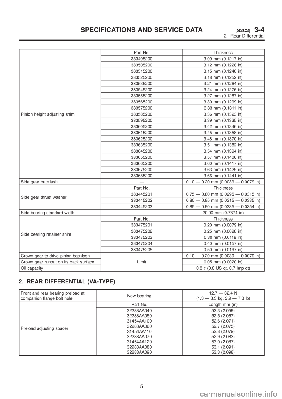
Pinion height adjusting shimPart No. Thickness
383495200 3.09 mm (0.1217 in)
383505200 3.12 mm (0.1228 in)
383515200 3.15 mm (0.1240 in)
383525200 3.18 mm (0.1252 in)
383535200 3.21 mm (0.1264 in)
383545200 3.24 mm (0.1276 in)
383555200 3.27 mm (0.1287 in)
383565200 3.30 mm (0.1299 in)
383575200 3.33 mm (0.1311 in)
383585200 3.36 mm (0.1323 in)
383595200 3.39 mm (0.1335 in)
383605200 3.42 mm (0.1346 in)
383615200 3.45 mm (0.1358 in)
383625200 3.48 mm (0.1370 in)
383635200 3.51 mm (0.1382 in)
383645200 3.54 mm (0.1394 in)
383655200 3.57 mm (0.1406 in)
383665200 3.60 mm (0.1417 in)
383675200 3.63 mm (0.1429 in)
383685200 3.66 mm (0.1441 in)
Side gear backlash Ð 0.10 Ð 0.20 mm (0.0039 Ð 0.0079 in)
Side gear thrust washerPart No. Thickness
383445201 0.75 Ð 0.80 mm (0.0295 Ð 0.0315 in)
383445202 0.80 Ð 0.85 mm (0.0315 Ð 0.0335 in)
383445203 0.85 Ð 0.90 mm (0.0335 Ð 0.0354 in)
Side bearing standard width Ð 20.00 mm (0.7874 in)
Side bearing retainer shimPart No. Thickness
383475201 0.20 mm (0.0079 in)
383475202 0.25 mm (0.0098 in)
383475203 0.30 mm (0.0118 in)
383475204 0.40 mm (0.0157 in)
383475205 0.50 mm (0.0197 in)
Crown gear to drive pinion backlash
Limit0.10 Ð 0.20 mm (0.0039 Ð 0.0079 in)
Crown gear runout on its back surface 0.05 mm (0.0020 in)
Oil capacity0.8(0.8 US qt, 0.7 Imp qt)
2. REAR DIFFERENTIAL (VA-TYPE)
Front and rear bearing preload at
companion flange bolt holeNew bearing12.7 Ð 32.4 N
(1.3 Ð 3.3 kg, 2.9 Ð 7.3 lb)
Preload adjusting spacerPart No. Length mm (in)
32288AA040
32288AA050
31454AA100
32288AA060
31454AA110
32288AA070
31454AA120
32288AA080
32288AA09052.3 (2.059)
52.5 (2.067)
52.6 (2.071)
52.7 (2.075)
52.8 (2.079)
52.9 (2.083)
53.0 (2.087)
53.1 (2.091)
53.3 (2.098)
5
[S2C2]3-4SPECIFICATIONS AND SERVICE DATA
2. Rear Differential
Page 655 of 1456

Preload adjusting washerPart No. Thickness mm (in)
38336AA000
38336AA120
38336AA010
38336AA130
38336AA020
38336AA140
38336AA030
38336AA150
38336AA040
38336AA160
38336AA050
38336AA170
38336AA060
38336AA180
38336AA070
38336AA190
38336AA080
38336AA200
38336AA090
38336AA210
38336AA100
38336AA220
38336AA1101.500 (0.0591)
1.513 (0.0596)
1.525 (0.0600)
1.538 (0.0606)
1.550 (0.0610)
1.563 (0.0615)
1.575 (0.0620)
1.588 (0.0625)
1.600 (0.0630)
1.613 (0.0635)
1.625 (0.0640)
1.638 (0.0645)
1.650 (0.0650)
1.663 (0.0655)
1.675 (0.0659)
1.688 (0.0665)
1.700 (0.0669)
1.713 (0.0674)
1.725 (0.0679)
1.738 (0.0684)
1.750 (0.0689)
1.763 (0.0694)
1.775 (0.0699)
Pinion height adjusting shimPart No. Thickness mm (in)
32295AA200
32295AA210
32295AA220
32295AA230
32295AA240
32295AA2500.150 (0.0059)
0.175 (0.0069)
0.200 (0.0079)
0.225 (0.0089)
0.250 (0.0098)
0.275 (0.0108)
Side gear backlash 0.05 Ð 0.15 mm (0.0020 Ð 0.0059 in)
Side gear thrust washerPart No. Thickness mm (in)
803135011
803135012
803135013
803135014
8031350150.925 Ð 0.950 (0.0364 Ð 0.0374)
0.950 Ð 0.975 (0.0374 Ð 0.0384)
0.975 Ð 1.000 (0.0384 Ð 0.0394)
1.000 Ð 1.025 (0.0394 Ð 0.0404)
1.025 Ð 1.050 (0.0404 Ð 0.0413)
Crown gear to drive pinion backlash
Limit0.10 Ð 0.15 (0.0039 Ð 0.0059)
Crown gear runout on its back surface 0.05 (0.0020)
Oil capacity0.8(0.8 US qt, 0.7 Imp qt)
D: REAR DIFFERENTIAL GEAR OIL
IRecommended oil
CAUTION:
Each oil manufacturer has its base oil and addi-
tives. Thus, do not mix two or more brands.
H3M1272A
6
3-4[S2D0]SPECIFICATIONS AND SERVICE DATA
2. Rear Differential
Page 658 of 1456
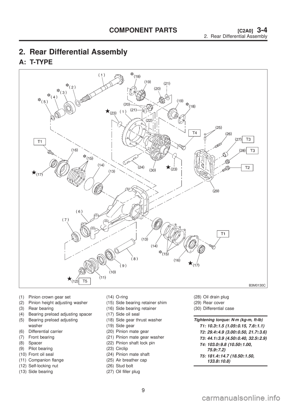
2. Rear Differential Assembly
A: T-TYPE
B3M0130C
(1) Pinion crown gear set
(2) Pinion height adjusting washer
(3) Rear bearing
(4) Bearing preload adjusting spacer
(5) Bearing preload adjusting
washer
(6) Differential carrier
(7) Front bearing
(8) Spacer
(9) Pilot bearing
(10) Front oil seal
(11) Companion flange
(12) Self-locking nut
(13) Side bearing(14) O-ring
(15) Side bearing retainer shim
(16) Side bearing retainer
(17) Side oil seal
(18) Side gear thrust washer
(19) Side gear
(20) Pinion mate gear
(21) Pinion mate gear washer
(22) Pinion shaft lock pin
(23) Circlip
(24) Pinion mate shaft
(25) Air breather cap
(26) Stud bolt
(27) Oil filler plug(28) Oil drain plug
(29) Rear cover
(30) Differential case
Tightening torque: N´m (kg-m, ft-lb)
T1:
10.3±1.5 (1.05±0.15, 7.6±1.1)
T2:29.4±4.9 (3.00±0.50, 21.7±3.6)
T3:44.1±3.9 (4.50±0.40, 32.5±2.9)
T4:103.0±9.8 (10.50±1.00,
75.9
±7.2)
T5:181.4±14.7 (18.50±1.50,
133.8
±10.8)
9
[C2A0]3-4COMPONENT PARTS
2. Rear Differential Assembly
Page 659 of 1456
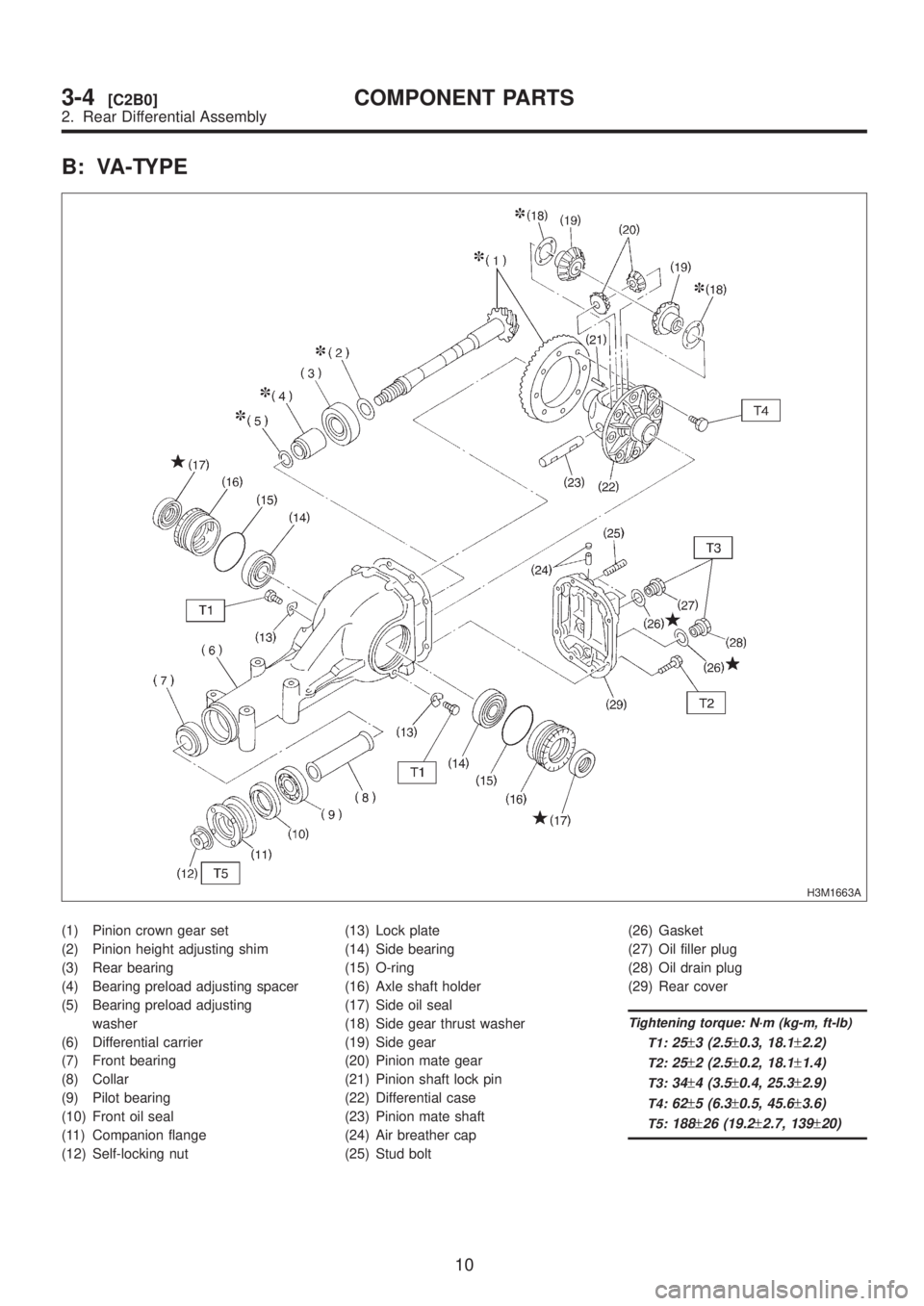
B: VA-TYPE
H3M1663A
(1) Pinion crown gear set
(2) Pinion height adjusting shim
(3) Rear bearing
(4) Bearing preload adjusting spacer
(5) Bearing preload adjusting
washer
(6) Differential carrier
(7) Front bearing
(8) Collar
(9) Pilot bearing
(10) Front oil seal
(11) Companion flange
(12) Self-locking nut(13) Lock plate
(14) Side bearing
(15) O-ring
(16) Axle shaft holder
(17) Side oil seal
(18) Side gear thrust washer
(19) Side gear
(20) Pinion mate gear
(21) Pinion shaft lock pin
(22) Differential case
(23) Pinion mate shaft
(24) Air breather cap
(25) Stud bolt(26) Gasket
(27) Oil filler plug
(28) Oil drain plug
(29) Rear cover
Tightening torque: N´m (kg-m, ft-lb)
T1:
25±3 (2.5±0.3, 18.1±2.2)
T2:25±2 (2.5±0.2, 18.1±1.4)
T3:34±4 (3.5±0.4, 25.3±2.9)
T4:62±5 (6.3±0.5, 45.6±3.6)
T5:188±26 (19.2±2.7, 139±20)
10
3-4[C2B0]COMPONENT PARTS
2. Rear Differential Assembly