Page 1088 of 1456

4) Tilt up assembly:
(1) Remove sunroof flame.
[W16A2].>
(2) Remove tilt up assembly.
B5M0485A
(3) Installation is in the reverse order of
removal.
B: ADJUSTMENT
1. SEDAN AND WAGON REAR (EXCEPT
OUTBACK)
1) Alignment of height between glass lid assembly
and roof panel:
(1) Remove guide rail cover.
(2) Loosen nuts and adjust height by adding
(Max: two pieces) and extracting (Max: one
piece) shim(s) (Standard: one piece) between
glass lid assembly and lid bracket.
Difference in height between glass lid assem-
bly and roof panel:
0
±0.5 mm (0±0.020 in)
B5M0314B
B5M0315B
2) Alignment of glass lid assembly with roof panel:
(1) Remove guide rail cover.
(2) Loosen nuts and move glass lid assembly
to either side to adjust front, rear, right, and left
side partitions.
Partition clearance:
7.0
±0.5 mm (0.276±0.020 in)
B5M0316A
3) Checking for movement of glass lid assembly
itself:
(1) Before installing sunroof motor, check glass
lid assembly for movement.
(2) Place a cloth on glass lid assembly and sun
shade, and attach a spring scale to glass lid
assembly edge using the cloth.
B5M0317
(3) Pull spring scale to measure force required
to move glass lid assembly.
Force required to move glass lid assembly
and sun shade trim:
Less than 196 N (20 kg, 44 lb)
Considerable effort is required to start glass lid
assembly moving, so take scale reading while
glass lid assembly is moving smoothly.
(4) If force required exceeds specifications,
check the following points:
IGlass lid assembly, sun shade and deflector and
guide rail assembly for improper installation
ICable for seizure
60
5-1[W16B1]SERVICE PROCEDURE
16. Sunroof
Page 1089 of 1456
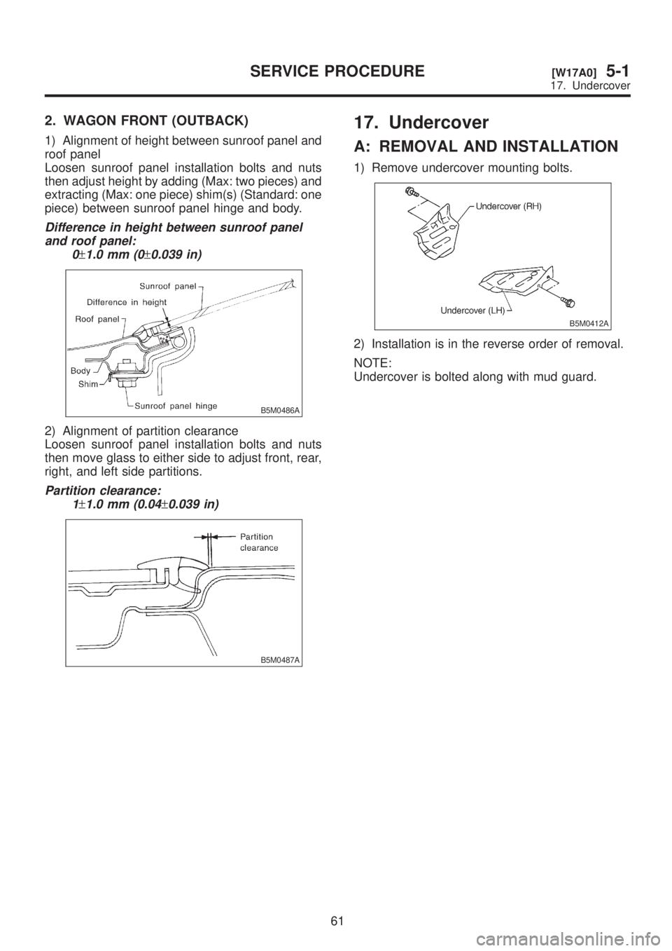
2. WAGON FRONT (OUTBACK)
1) Alignment of height between sunroof panel and
roof panel
Loosen sunroof panel installation bolts and nuts
then adjust height by adding (Max: two pieces) and
extracting (Max: one piece) shim(s) (Standard: one
piece) between sunroof panel hinge and body.
Difference in height between sunroof panel
and roof panel:
0
±1.0 mm (0±0.039 in)
B5M0486A
2) Alignment of partition clearance
Loosen sunroof panel installation bolts and nuts
then move glass to either side to adjust front, rear,
right, and left side partitions.
Partition clearance:
1
±1.0 mm (0.04±0.039 in)
B5M0487A
17. Undercover
A: REMOVAL AND INSTALLATION
1) Remove undercover mounting bolts.
B5M0412A
2) Installation is in the reverse order of removal.
NOTE:
Undercover is bolted along with mud guard.
61
[W17A0]5-1SERVICE PROCEDURE
17. Undercover
Page 1090 of 1456
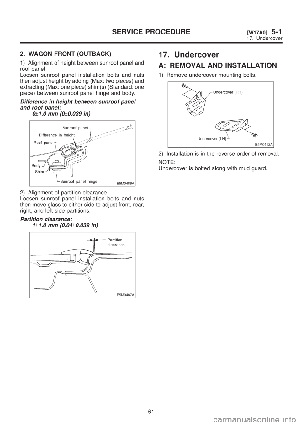
2. WAGON FRONT (OUTBACK)
1) Alignment of height between sunroof panel and
roof panel
Loosen sunroof panel installation bolts and nuts
then adjust height by adding (Max: two pieces) and
extracting (Max: one piece) shim(s) (Standard: one
piece) between sunroof panel hinge and body.
Difference in height between sunroof panel
and roof panel:
0
±1.0 mm (0±0.039 in)
B5M0486A
2) Alignment of partition clearance
Loosen sunroof panel installation bolts and nuts
then move glass to either side to adjust front, rear,
right, and left side partitions.
Partition clearance:
1
±1.0 mm (0.04±0.039 in)
B5M0487A
17. Undercover
A: REMOVAL AND INSTALLATION
1) Remove undercover mounting bolts.
B5M0412A
2) Installation is in the reverse order of removal.
NOTE:
Undercover is bolted along with mud guard.
61
[W17A0]5-1SERVICE PROCEDURE
17. Undercover
Page 1133 of 1456
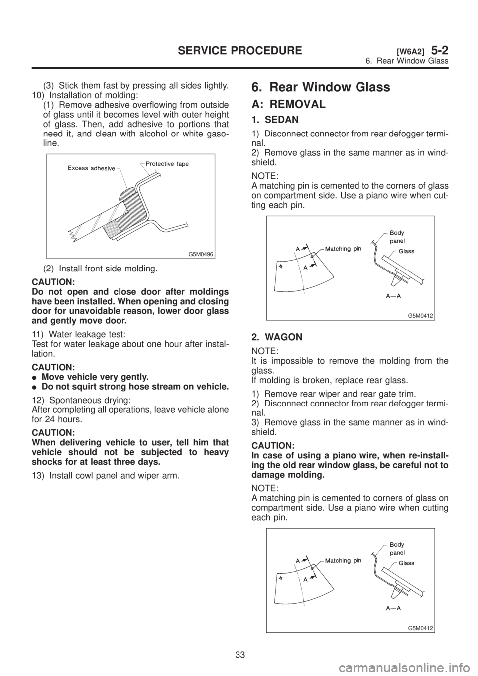
(3) Stick them fast by pressing all sides lightly.
10) Installation of molding:
(1) Remove adhesive overflowing from outside
of glass until it becomes level with outer height
of glass. Then, add adhesive to portions that
need it, and clean with alcohol or white gaso-
line.
G5M0496
(2) Install front side molding.
CAUTION:
Do not open and close door after moldings
have been installed. When opening and closing
door for unavoidable reason, lower door glass
and gently move door.
11) Water leakage test:
Test for water leakage about one hour after instal-
lation.
CAUTION:
IMove vehicle very gently.
IDo not squirt strong hose stream on vehicle.
12) Spontaneous drying:
After completing all operations, leave vehicle alone
for 24 hours.
CAUTION:
When delivering vehicle to user, tell him that
vehicle should not be subjected to heavy
shocks for at least three days.
13) Install cowl panel and wiper arm.
6. Rear Window Glass
A: REMOVAL
1. SEDAN
1) Disconnect connector from rear defogger termi-
nal.
2) Remove glass in the same manner as in wind-
shield.
NOTE:
A matching pin is cemented to the corners of glass
on compartment side. Use a piano wire when cut-
ting each pin.
G5M0412
2. WAGON
NOTE:
It is impossible to remove the molding from the
glass.
If molding is broken, replace rear glass.
1) Remove rear wiper and rear gate trim.
2) Disconnect connector from rear defogger termi-
nal.
3) Remove glass in the same manner as in wind-
shield.
CAUTION:
In case of using a piano wire, when re-install-
ing the old rear window glass, be careful not to
damage molding.
NOTE:
A matching pin is cemented to corners of glass on
compartment side. Use a piano wire when cutting
each pin.
G5M0412
33
[W6A2]5-2SERVICE PROCEDURE
6. Rear Window Glass
Page 1134 of 1456
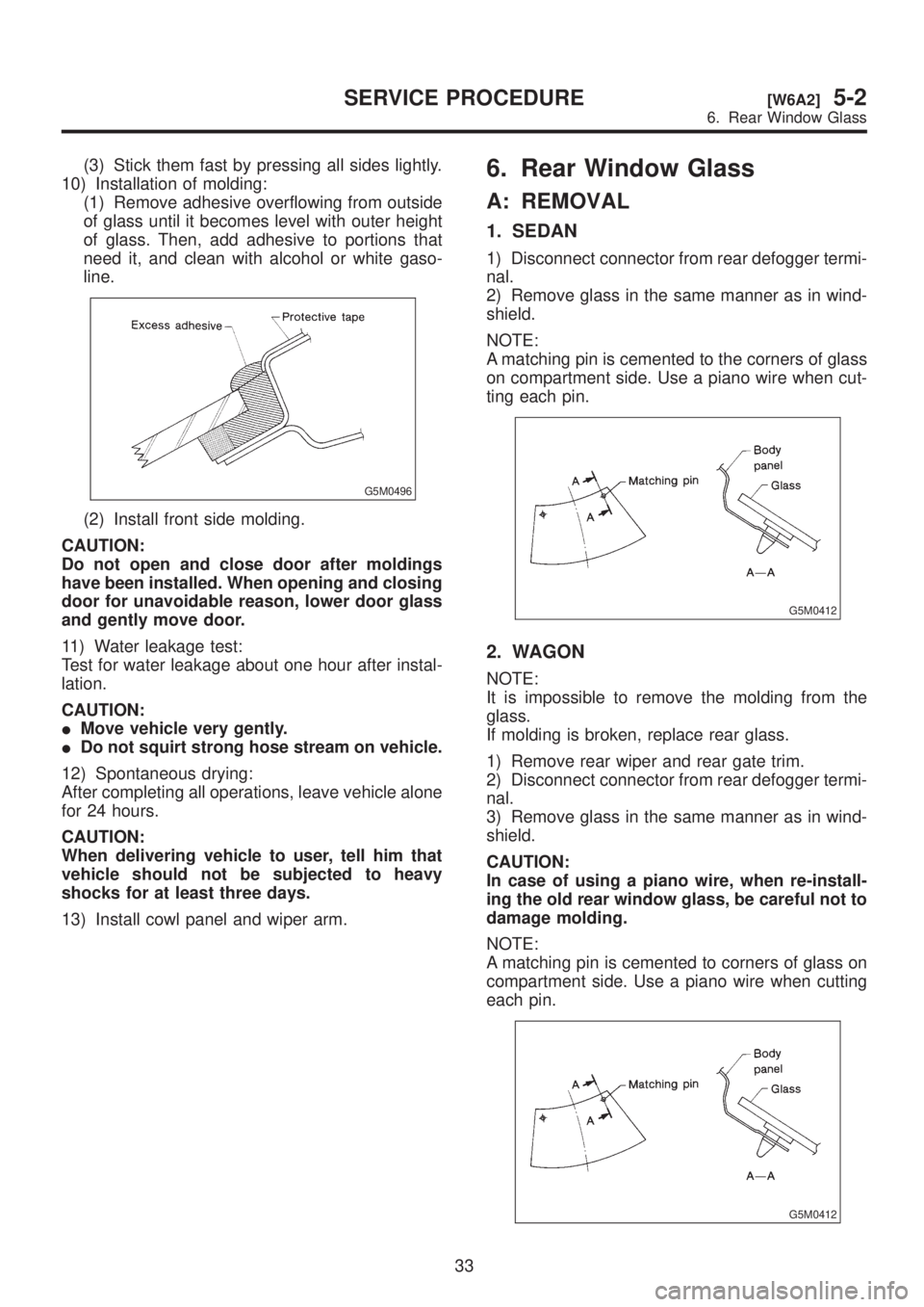
(3) Stick them fast by pressing all sides lightly.
10) Installation of molding:
(1) Remove adhesive overflowing from outside
of glass until it becomes level with outer height
of glass. Then, add adhesive to portions that
need it, and clean with alcohol or white gaso-
line.
G5M0496
(2) Install front side molding.
CAUTION:
Do not open and close door after moldings
have been installed. When opening and closing
door for unavoidable reason, lower door glass
and gently move door.
11) Water leakage test:
Test for water leakage about one hour after instal-
lation.
CAUTION:
IMove vehicle very gently.
IDo not squirt strong hose stream on vehicle.
12) Spontaneous drying:
After completing all operations, leave vehicle alone
for 24 hours.
CAUTION:
When delivering vehicle to user, tell him that
vehicle should not be subjected to heavy
shocks for at least three days.
13) Install cowl panel and wiper arm.
6. Rear Window Glass
A: REMOVAL
1. SEDAN
1) Disconnect connector from rear defogger termi-
nal.
2) Remove glass in the same manner as in wind-
shield.
NOTE:
A matching pin is cemented to the corners of glass
on compartment side. Use a piano wire when cut-
ting each pin.
G5M0412
2. WAGON
NOTE:
It is impossible to remove the molding from the
glass.
If molding is broken, replace rear glass.
1) Remove rear wiper and rear gate trim.
2) Disconnect connector from rear defogger termi-
nal.
3) Remove glass in the same manner as in wind-
shield.
CAUTION:
In case of using a piano wire, when re-install-
ing the old rear window glass, be careful not to
damage molding.
NOTE:
A matching pin is cemented to corners of glass on
compartment side. Use a piano wire when cutting
each pin.
G5M0412
33
[W6A2]5-2SERVICE PROCEDURE
6. Rear Window Glass
Page 1238 of 1456
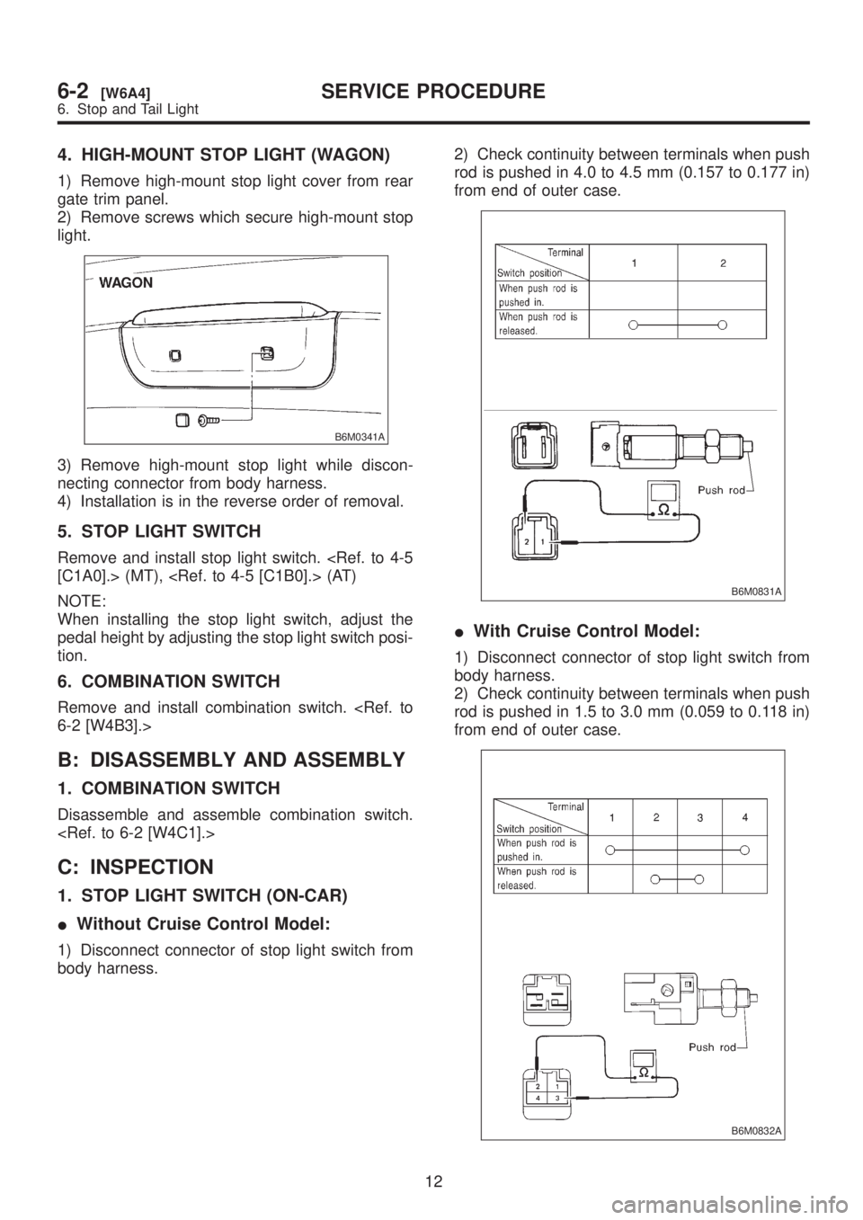
4. HIGH-MOUNT STOP LIGHT (WAGON)
1) Remove high-mount stop light cover from rear
gate trim panel.
2) Remove screws which secure high-mount stop
light.
B6M0341A
3) Remove high-mount stop light while discon-
necting connector from body harness.
4) Installation is in the reverse order of removal.
5. STOP LIGHT SWITCH
Remove and install stop light switch.
[C1A0].> (MT), (AT)
NOTE:
When installing the stop light switch, adjust the
pedal height by adjusting the stop light switch posi-
tion.
6. COMBINATION SWITCH
Remove and install combination switch.
6-2 [W4B3].>
B: DISASSEMBLY AND ASSEMBLY
1. COMBINATION SWITCH
Disassemble and assemble combination switch.
C: INSPECTION
1. STOP LIGHT SWITCH (ON-CAR)
IWithout Cruise Control Model:
1) Disconnect connector of stop light switch from
body harness.2) Check continuity between terminals when push
rod is pushed in 4.0 to 4.5 mm (0.157 to 0.177 in)
from end of outer case.
B6M0831A
IWith Cruise Control Model:
1) Disconnect connector of stop light switch from
body harness.
2) Check continuity between terminals when push
rod is pushed in 1.5 to 3.0 mm (0.059 to 0.118 in)
from end of outer case.
B6M0832A
12
6-2[W6A4]SERVICE PROCEDURE
6. Stop and Tail Light